EP2255712A2 - Serpillière pouvant tourner téléscopiquement - Google Patents
Serpillière pouvant tourner téléscopiquement Download PDFInfo
- Publication number
- EP2255712A2 EP2255712A2 EP10162977A EP10162977A EP2255712A2 EP 2255712 A2 EP2255712 A2 EP 2255712A2 EP 10162977 A EP10162977 A EP 10162977A EP 10162977 A EP10162977 A EP 10162977A EP 2255712 A2 EP2255712 A2 EP 2255712A2
- Authority
- EP
- European Patent Office
- Prior art keywords
- internal
- external
- rod
- clamping sleeve
- engaging element
- Prior art date
- Legal status (The legal status is an assumption and is not a legal conclusion. Google has not performed a legal analysis and makes no representation as to the accuracy of the status listed.)
- Granted
Links
- 238000007373 indentation Methods 0.000 claims description 6
- XLYOFNOQVPJJNP-UHFFFAOYSA-N water Substances O XLYOFNOQVPJJNP-UHFFFAOYSA-N 0.000 claims description 5
- 238000003780 insertion Methods 0.000 claims description 2
- 230000037431 insertion Effects 0.000 claims description 2
- 230000033001 locomotion Effects 0.000 description 9
- 229920000742 Cotton Polymers 0.000 description 2
- 239000004744 fabric Substances 0.000 description 2
- 229910052751 metal Inorganic materials 0.000 description 2
- 239000002184 metal Substances 0.000 description 2
- 229910052782 aluminium Inorganic materials 0.000 description 1
- XAGFODPZIPBFFR-UHFFFAOYSA-N aluminium Chemical compound [Al] XAGFODPZIPBFFR-UHFFFAOYSA-N 0.000 description 1
- 230000006835 compression Effects 0.000 description 1
- 238000007906 compression Methods 0.000 description 1
- 235000004879 dioscorea Nutrition 0.000 description 1
- 230000000694 effects Effects 0.000 description 1
- 238000001746 injection moulding Methods 0.000 description 1
- 239000007769 metal material Substances 0.000 description 1
- 238000000034 method Methods 0.000 description 1
- 229910052755 nonmetal Inorganic materials 0.000 description 1
- 238000002791 soaking Methods 0.000 description 1
- 238000005406 washing Methods 0.000 description 1
Images


Classifications
-
- A—HUMAN NECESSITIES
- A47—FURNITURE; DOMESTIC ARTICLES OR APPLIANCES; COFFEE MILLS; SPICE MILLS; SUCTION CLEANERS IN GENERAL
- A47L—DOMESTIC WASHING OR CLEANING; SUCTION CLEANERS IN GENERAL
- A47L13/00—Implements for cleaning floors, carpets, furniture, walls, or wall coverings
- A47L13/10—Scrubbing; Scouring; Cleaning; Polishing
- A47L13/20—Mops
-
- A—HUMAN NECESSITIES
- A47—FURNITURE; DOMESTIC ARTICLES OR APPLIANCES; COFFEE MILLS; SPICE MILLS; SUCTION CLEANERS IN GENERAL
- A47L—DOMESTIC WASHING OR CLEANING; SUCTION CLEANERS IN GENERAL
- A47L13/00—Implements for cleaning floors, carpets, furniture, walls, or wall coverings
- A47L13/10—Scrubbing; Scouring; Cleaning; Polishing
- A47L13/14—Scrubbing; Scouring; Cleaning; Polishing combined with squeezing or wringing devices
-
- A—HUMAN NECESSITIES
- A61—MEDICAL OR VETERINARY SCIENCE; HYGIENE
- A61P—SPECIFIC THERAPEUTIC ACTIVITY OF CHEMICAL COMPOUNDS OR MEDICINAL PREPARATIONS
- A61P35/00—Antineoplastic agents
-
- B—PERFORMING OPERATIONS; TRANSPORTING
- B25—HAND TOOLS; PORTABLE POWER-DRIVEN TOOLS; MANIPULATORS
- B25G—HANDLES FOR HAND IMPLEMENTS
- B25G1/00—Handle constructions
- B25G1/04—Handle constructions telescopic; extensible; sectional
Definitions
- the invention relates to a telescopically rotatable mop, and more particularly to a structure that ensures a smooth operation in dewatering the mop with one hand only and without use of the feet.
- the aforementioned device can improve the inconvenient way of wringing the mop fabrics by hands, yet the operation still requires a user to step on the pedal continuously by one foot, and keep the user's body in balance by another foot.
- Such arrangement not only involves an inconvenient operation, but also endangers the safety of users when the users fail to stand stably or fall. Therefore, it is necessary to develop a mop with an easy, convenient and safe operation in dewatering.
- An object of the invention is to provide a telescopically rotatable mop that permits a convenient operation with less effort when the internal and external rods rotate in a telescopic way. In this way, the operation failure may be minimized and the service life may be increased.
- the invention includes:
- the actuating element is rotated by a linear motion of the driving element when the external rod is moved up-and-down.
- the engaging element is driven in rotation in one direction only, thereby creating a continuous rotation of the internal rod and the disc body in the same direction by the inertia force.
- a centrifugal force is produced to throw away the water absorbed in the mop yarns.
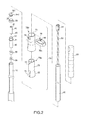
- a mop in accordance with the invention includes an internal rod 10, an external rod 20, an engaging element 30, a driving element 50, an actuating element 40, a disc body 60, and a locking mechanism 70.
- the internal rod 10 is constructed as a hollow circular tube and made by metal or non-metal material. Therefore, it can be an aluminum tube or a plastic tube.
- the external rod 20 includes a bottom portion in a telescopic connection with a top portion of the internal rod 10. According to the embodiment, the operator can hold on the external rod 20 to conduct a telescopic motion on the internal rod 10.
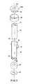
- the engaging element 30 is positioned within the opening at the top of the internal rod 10.
- an annular element 33 and a fixing cap 34 are mounted and fixed on the engaging element 30 after the engaging element 30 is placed within the top of the internal rod 10.
- the upper portion of the engaging element 30 is externally provided with a flange 31.
- the fixing cap 34 includes a through hole 341 at the top thereof and a projecting flange 342 at the external rim thereof.
- the bottom of the fixing cap 34 fits into an opening 32 of the engaging element 30 in place.
- the bottom of the internal rim of the engaging element 30 is provided with driven teeth 35.
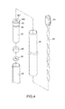
- the driving element 50 is formed in an elongated shape and positioned within the external rod 20 in such a way that the driving element 50 is moved up and down synchronically with the external rod 20.
- the driving element 50 includes a fixing block 51 fastened by a fixing element (not shown) or in a riveting way within the top end of the external rod 20.
- a protection sleeve 22 is mounted on the external rod 20.
- the actuating element 40 is positioned within the engaging element 30 for accommodating the driving element 50.
- the driving element 50 is constructed as a worm or a threaded piece.
- the internal wall of the actuating element 40 has to be formed to be a threaded sleeve 41.
- the actuating element 40 is correspondingly provided with a worm thread or an elongated groove such that the driving element 50 may impart a rotary motion to the actuating element 40 by means of the up-and-down linear movement of the external rod 20.
- the driving element 50 is constructed as a threaded piece.
- the threaded sleeve 41 at the internal end of the actuating element 40 is constructed as an elongated groove such that the up-and-down movement of the driving element 50 in the threaded sleeve 41 may impart a rotary motion to the actuating element 40 within the engaging element 30.
- the bottom of the actuating element 40 is provided with downward driving teeth 42 in contract with the upward driven teeth 35 of the engaging element 30. Since the engaging teeth are formed in an inclined way, the drive is subject to a rotation in a certain direction.
- the engaging element 30 is subject to a clockwise rotation like the actuating element 40 when the actuating element 40 is driven by the driving element 50.
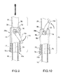
- the actuating element 40 is driven when the driving element 50 is compressed downward. Meanwhile, the engaging element 30 is brought in clockwise rotation. To the contrary, as shown in FIG. 8 , when the driving element 50 is pulled upward, the actuating element 40 is brought in a counterclockwise rotation. At that time, the downward driving teeth 42 of the actuating element 40 is driven in an idle non-rotation state relative to the driving teeth 35 of the engaging element 30. In other words, the engaging element 30 remains unmoved such that the driving element 50 can be returned to the original position for a renewed downward compression to drive the engaging element 30 again.
- the disc body 60 is secured to the bottom of the internal rod 10 and includes mop yarns 61.
- the locking mechanism 70 is mounted on the external rod 20 for locking the internal rod 10 and the external rod 20 in place or for unlocking them in a telescopic state. As shown in FIGS. 2 , 9 and 10 , the locking mechanism 70 includes an internal clamping sleeve 70a, an external clamping sleeve 70b, and a U-shaped lever 70c, but should not limited thereto:
- the external clamping sleeve 70b is mounted on the periphery of the internal clamping sleeve 70a.
- the upper portion of the external clamping sleeve 70b is provided with an external tube 75 corresponding to the internal tube 71.
- the external tube 75 includes at both sides thereof two mounting holes 76 in alignment with the positioning holes 72 of the internal tube 71.
- the mounting holes 76 are formed as a non-circular and rectangular hole, but should be limited thereto.
- the mounting holes 76 and the positioning holes 72 are not concentrically positioned such that cams 78 within the mounting holes 76 tend to conduct an eccentric push action.
- a bell mouth 77 is formed at the lower portion of the external clamping sleeve 70b for fitting over the conic body 73.
- the U-shaped lever 70c includes a swivel protrusion 79 and an eccentric cam 78 at the internal wall of both sides thereof for fitting into the positioning holes 72 of the internal clamping sleeve 70a and the mounting holes 76 of the external clamping sleeve 70b.
- the eccentric cams 78 are positioned within the mounting holes 76.
- the swivel protrusions 79 together with the eccentric cams 38 and the U-shaped locking arm 30c are formed by the injection-molding process.
- the swivel protrusion 39 can be replaced by a processed metal post.
- the eccentric cams 78 are offset within the mounting holes 76, thereby moving the external clamping sleeve 70b on the periphery of the internal clamping sleeve 70a upward or downward.
- the external rim of the internal clamping sleeve 70a rises when the U-shaped lever 70c is pushed downward. Due to the action of the indentation 74, the bell mouth 77 of the external clamping sleeve 70b is brought in a loosened position relative to the conic body 73 of the internal clamping sleeve 70a.
- the internal rod 10 and the external rod 20 are unlocked and brought in a telescopic state.
- the external clamping sleeve 70b is moved downward when the U-shaped lever 70c is pulled upward. In this way, the internal clamping sleeve 70a is so clamped that the internal and external rods 10, 20 are fixed in place.
- the internal rod 10 won't be acted upon thereby and remains to rotate in the same direction due to the action of the inertia force.
- the internal rod 10 and the disc body 60 may be rotated more than 10 times within a dewatering basket 81 of a bucket body 80 by means that the user pushes downward and pulls upward the external rod 20 for a few times.
- the dewatering basket 81 is rotatable within the bucket body 80.
- the dewatering basket 81 in accordance with the invention may be synchronically driven in rotation when the disc body 60 is rotated by the internal rod 10. In this way, the mop yarns 61 of the disc body 60 are subject to the centrifugal force for dewatering. Meanwhile, the water removed may be received within the bucket body 80.
- the engaging element 30 is constructed as a cylindrical body with the middle and lower parts secured to the inside of the internal rod 10.
- An annular element 33 rotatable clockwise and counterclockwise at 360° is mounted on the top portion of the engaging element 30 projecting in an exposed manner from the internal rod 10.
- the external diameter D1 of the annular element 33 is greater than the external diameter D2 of the internal rod 10, but smaller than is almost the same to the internal diameter ⁇ 1 of the external rod 20.
- the length L1 of the driving element 50 is smaller than the length L2 of the inside of the engaging element 30.
- the bottom of the fixing cap 34 is extended and secured to the opening 32 of the engaging element 30 in such a way that a gap S is provided between the fixing cap 34 and the top of the actuating element 40.
- the fixing cap 34 includes at the top thereof a projecting flange 342 (whose external diameter is greater than the external diameter D2 of the internal rod 10, but smaller than the external diameter D1 of the annular element 33) for positioning the annular element 33 on the periphery of the top portion of the engaging element 30 without affecting the rotation of the annular element 33 within the external rod 20.
- the driving element 50 includes at the bottom thereof a position-limiting element 52 and a positioning element 53 for a reliable stop of the driving element 50 in a preset position and for a practical protection of the internal rod 10 and the driving element 50 from being detached from the internal rod 10.
- the structure in accordance with the invention is provided to resolve the problems with respect to the telescopic and rotary motions of the internal and external rods 10, 20. Moreover, the structure permits a more smooth operation with less effort. Meanwhile, the noise may be reduced and the service life may be increased.
Landscapes
- Health & Medical Sciences (AREA)
- Chemical & Material Sciences (AREA)
- Chemical Kinetics & Catalysis (AREA)
- General Chemical & Material Sciences (AREA)
- Medicinal Chemistry (AREA)
- Nuclear Medicine, Radiotherapy & Molecular Imaging (AREA)
- Organic Chemistry (AREA)
- Pharmacology & Pharmacy (AREA)
- Life Sciences & Earth Sciences (AREA)
- Animal Behavior & Ethology (AREA)
- General Health & Medical Sciences (AREA)
- Public Health (AREA)
- Veterinary Medicine (AREA)
- Engineering & Computer Science (AREA)
- Mechanical Engineering (AREA)
- Cleaning Implements For Floors, Carpets, Furniture, Walls, And The Like (AREA)
Priority Applications (1)
| Application Number | Priority Date | Filing Date | Title |
|---|---|---|---|
| PL10162977T PL2255712T3 (pl) | 2009-05-27 | 2010-05-17 | Teleskopowo obracany mop |
Applications Claiming Priority (1)
| Application Number | Priority Date | Filing Date | Title |
|---|---|---|---|
| TW098209417U TWM368410U (en) | 2009-05-27 | 2009-05-27 | Mop converting vertically linear displacement into uni-directional dehydration |
Publications (3)
| Publication Number | Publication Date |
|---|---|
| EP2255712A2 true EP2255712A2 (fr) | 2010-12-01 |
| EP2255712A3 EP2255712A3 (fr) | 2011-11-02 |
| EP2255712B1 EP2255712B1 (fr) | 2012-12-26 |
Family
ID=42668722
Family Applications (1)
| Application Number | Title | Priority Date | Filing Date |
|---|---|---|---|
| EP10162977A Active EP2255712B1 (fr) | 2009-05-27 | 2010-05-17 | Serpillière pouvant tourner téléscopiquement |
Country Status (5)
| Country | Link |
|---|---|
| EP (1) | EP2255712B1 (fr) |
| ES (1) | ES2401546T3 (fr) |
| MY (1) | MY154735A (fr) |
| PL (1) | PL2255712T3 (fr) |
| TW (1) | TWM368410U (fr) |
Cited By (10)
| Publication number | Priority date | Publication date | Assignee | Title |
|---|---|---|---|---|
| CN102389282A (zh) * | 2011-08-19 | 2012-03-28 | 林义斌 | 螺旋驱动装置及使用该装置的拖把 |
| WO2013043632A1 (fr) * | 2011-09-19 | 2013-03-28 | Travelpro International Inc. | Manche et stabilisateur télescopique de bagage |
| EP2650089A1 (fr) | 2012-04-11 | 2013-10-16 | Leifheit Ag | Mécanisme de blocage pour une tige de télescope |
| EP2799189A1 (fr) | 2013-05-03 | 2014-11-05 | Leifheit Ag | Mécanisme de blocage pour une tige télescopique |
| US8978194B1 (en) | 2014-04-28 | 2015-03-17 | Telebrands Corp. | Rotating mop handle and bucket assembly |
| CN115046113A (zh) * | 2022-08-15 | 2022-09-13 | 临沂澳百奇建筑材料有限公司 | 一种建筑基坑工程检测装置 |
| USD973295S1 (en) | 2021-04-20 | 2022-12-20 | The Libman Company | Bucket |
| USD973294S1 (en) | 2021-04-20 | 2022-12-20 | The Libman Company | Mop |
| US11717130B2 (en) | 2021-04-20 | 2023-08-08 | The Libman Company | Mop system with rotating mop head |
| US12245732B2 (en) | 2023-05-03 | 2025-03-11 | The Libman Company | Grip handle assembly for a mop |
Families Citing this family (7)
| Publication number | Priority date | Publication date | Assignee | Title |
|---|---|---|---|---|
| CN201585947U (zh) * | 2010-01-14 | 2010-09-22 | 金国寿 | 旋动机构 |
| CN103222837B (zh) * | 2010-05-04 | 2014-05-07 | 赵一美 | 拖把的清洗方法及拖把的清洗和脱水方法 |
| CN103654664B (zh) * | 2013-11-26 | 2015-12-02 | 嘉兴捷顺旅游制品有限公司 | 升降旋转式拖把清洗脱水组合装置 |
| USD720905S1 (en) | 2014-04-30 | 2015-01-06 | Telebrands Corp. | Base for a cleaning apparatus |
| USD723758S1 (en) | 2014-05-20 | 2015-03-03 | Telebrands, Corp. | Dual spout mop bucket |
| USD723234S1 (en) | 2014-05-20 | 2015-02-24 | Telebrands Corp. | Dual spout mop bucket with agitator |
| USD746528S1 (en) | 2014-05-23 | 2015-12-29 | Telebrands Corp. | Mop ring |
Family Cites Families (2)
| Publication number | Priority date | Publication date | Assignee | Title |
|---|---|---|---|---|
| GB235684A (en) * | 1924-04-17 | 1925-06-25 | Gerald Lawrenoe Opperman | Improvements in and relating to mops |
| DE102005023084A1 (de) * | 2005-05-13 | 2006-11-23 | Leifheit Ag | Vorrichtung zum Trocknen eines Wischmops |
-
2009
- 2009-05-27 TW TW098209417U patent/TWM368410U/zh not_active IP Right Cessation
-
2010
- 2010-05-17 PL PL10162977T patent/PL2255712T3/pl unknown
- 2010-05-17 EP EP10162977A patent/EP2255712B1/fr active Active
- 2010-05-17 ES ES10162977T patent/ES2401546T3/es active Active
- 2010-05-25 MY MYPI2010002421A patent/MY154735A/en unknown
Cited By (16)
| Publication number | Priority date | Publication date | Assignee | Title |
|---|---|---|---|---|
| CN102389282A (zh) * | 2011-08-19 | 2012-03-28 | 林义斌 | 螺旋驱动装置及使用该装置的拖把 |
| CN102389282B (zh) * | 2011-08-19 | 2014-12-24 | 林义斌 | 螺旋驱动装置及使用该装置的拖把 |
| WO2013043632A1 (fr) * | 2011-09-19 | 2013-03-28 | Travelpro International Inc. | Manche et stabilisateur télescopique de bagage |
| USD699438S1 (en) | 2011-09-19 | 2014-02-18 | Travelpro International Inc. | Telescoping handle |
| EP2650089A1 (fr) | 2012-04-11 | 2013-10-16 | Leifheit Ag | Mécanisme de blocage pour une tige de télescope |
| EP2799189A1 (fr) | 2013-05-03 | 2014-11-05 | Leifheit Ag | Mécanisme de blocage pour une tige télescopique |
| US9730568B2 (en) | 2014-04-28 | 2017-08-15 | Telebrands Corp. | Rotating mop handle and bucket assembly |
| US8997305B1 (en) | 2014-04-28 | 2015-04-07 | Telebrands Corp. | Rotating mop handle and bucket assembly |
| US8978194B1 (en) | 2014-04-28 | 2015-03-17 | Telebrands Corp. | Rotating mop handle and bucket assembly |
| USD973295S1 (en) | 2021-04-20 | 2022-12-20 | The Libman Company | Bucket |
| USD973294S1 (en) | 2021-04-20 | 2022-12-20 | The Libman Company | Mop |
| US11717130B2 (en) | 2021-04-20 | 2023-08-08 | The Libman Company | Mop system with rotating mop head |
| US12605031B2 (en) | 2021-04-20 | 2026-04-21 | The Libman Company | Mop system with rotating mop head |
| CN115046113A (zh) * | 2022-08-15 | 2022-09-13 | 临沂澳百奇建筑材料有限公司 | 一种建筑基坑工程检测装置 |
| CN115046113B (zh) * | 2022-08-15 | 2022-11-08 | 临沂澳百奇建筑材料有限公司 | 一种建筑基坑工程检测装置 |
| US12245732B2 (en) | 2023-05-03 | 2025-03-11 | The Libman Company | Grip handle assembly for a mop |
Also Published As
| Publication number | Publication date |
|---|---|
| EP2255712A3 (fr) | 2011-11-02 |
| MY154735A (en) | 2015-07-15 |
| ES2401546T3 (es) | 2013-04-22 |
| TWM368410U (en) | 2009-11-11 |
| PL2255712T3 (pl) | 2013-04-30 |
| EP2255712B1 (fr) | 2012-12-26 |
Similar Documents
| Publication | Publication Date | Title |
|---|---|---|
| US8220101B2 (en) | Telescopically rotatable mop | |
| EP2255712B1 (fr) | Serpillière pouvant tourner téléscopiquement | |
| US8291544B2 (en) | Mop with the function of dewatering the yarns by twisting in a single direction via an up-and-down linear motion | |
| US8336160B2 (en) | Dual rotating dewater bucket and mop thereof | |
| US8291538B2 (en) | Mop structure of converting vertical linear displacement into unidirectional rotation for dewatering a mop | |
| US8826486B2 (en) | Mop cleaning set | |
| KR200458282Y1 (ko) | 선형의 상하운동을 매개로 한 일 방향의 트위스팅을 통해 걸레를 탈수하는 기능을 갖는 자루걸레 | |
| US8112840B2 (en) | Disc rotating and positioning structure of a mop | |
| KR101373410B1 (ko) | 나선형 구동 기구 및 이를 구비한 스핀 몹 | |
| CN101919679B (zh) | 清洁工具 | |
| JP2013138849A (ja) | 清掃モップ及びその洗浄バケツ | |
| JP2013138849A5 (fr) | ||
| WO2025075859A1 (fr) | Ensemble balai à franges avec manchon d'essorage coulissant, rotatif et de serrage | |
| US8978193B2 (en) | Spin mop | |
| CN101884516B (zh) | 一种拖把桶及与其配套的拖把 | |
| AU2010101339A4 (en) | Telescopically rotatable mop | |
| US7891039B2 (en) | Cleaning apparatus with fast wringing ability | |
| CN210697444U (zh) | 一种清洁工具 | |
| KR200462559Y1 (ko) | 회전접이식 자루걸레 | |
| CN201505105U (zh) | 以上下线性位移转换成单向驱转脱水的拖把 | |
| CN110151079A (zh) | 清洁工具 | |
| CA2708621C (fr) | Balai a laver muni d'un dispositif d'essorage | |
| CN201861575U (zh) | 旋转式拖把组合 | |
| KR20120003264A (ko) | 회전 탈수식 밀대를 갖는 클리너 | |
| JP6726712B2 (ja) | 遠心脱水モップ |
Legal Events
| Date | Code | Title | Description |
|---|---|---|---|
| PUAI | Public reference made under article 153(3) epc to a published international application that has entered the european phase |
Free format text: ORIGINAL CODE: 0009012 |
|
| AK | Designated contracting states |
Kind code of ref document: A2 Designated state(s): AL AT BE BG CH CY CZ DE DK EE ES FI FR GB GR HR HU IE IS IT LI LT LU LV MC MK MT NL NO PL PT RO SE SI SK SM TR |
|
| AX | Request for extension of the european patent |
Extension state: BA ME RS |
|
| PUAL | Search report despatched |
Free format text: ORIGINAL CODE: 0009013 |
|
| AK | Designated contracting states |
Kind code of ref document: A3 Designated state(s): AL AT BE BG CH CY CZ DE DK EE ES FI FR GB GR HR HU IE IS IT LI LT LU LV MC MK MT NL NO PL PT RO SE SI SK SM TR |
|
| AX | Request for extension of the european patent |
Extension state: BA ME RS |
|
| RIC1 | Information provided on ipc code assigned before grant |
Ipc: A47L 13/20 20060101AFI20110923BHEP |
|
| 17P | Request for examination filed |
Effective date: 20120329 |
|
| GRAP | Despatch of communication of intention to grant a patent |
Free format text: ORIGINAL CODE: EPIDOSNIGR1 |
|
| GRAS | Grant fee paid |
Free format text: ORIGINAL CODE: EPIDOSNIGR3 |
|
| GRAA | (expected) grant |
Free format text: ORIGINAL CODE: 0009210 |
|
| AK | Designated contracting states |
Kind code of ref document: B1 Designated state(s): AL AT BE BG CH CY CZ DE DK EE ES FI FR GB GR HR HU IE IS IT LI LT LU LV MC MK MT NL NO PL PT RO SE SI SK SM TR |
|
| REG | Reference to a national code |
Ref country code: GB Ref legal event code: FG4D |
|
| REG | Reference to a national code |
Ref country code: CH Ref legal event code: EP |
|
| REG | Reference to a national code |
Ref country code: AT Ref legal event code: REF Ref document number: 590004 Country of ref document: AT Kind code of ref document: T Effective date: 20130115 |
|
| REG | Reference to a national code |
Ref country code: DE Ref legal event code: R096 Ref document number: 602010004268 Country of ref document: DE Effective date: 20130228 |
|
| REG | Reference to a national code |
Ref country code: SE Ref legal event code: TRGR |
|
| REG | Reference to a national code |
Ref country code: ES Ref legal event code: FG2A Ref document number: 2401546 Country of ref document: ES Kind code of ref document: T3 Effective date: 20130422 |
|
| PG25 | Lapsed in a contracting state [announced via postgrant information from national office to epo] |
Ref country code: NO Free format text: LAPSE BECAUSE OF FAILURE TO SUBMIT A TRANSLATION OF THE DESCRIPTION OR TO PAY THE FEE WITHIN THE PRESCRIBED TIME-LIMIT Effective date: 20130326 Ref country code: LT Free format text: LAPSE BECAUSE OF FAILURE TO SUBMIT A TRANSLATION OF THE DESCRIPTION OR TO PAY THE FEE WITHIN THE PRESCRIBED TIME-LIMIT Effective date: 20121226 Ref country code: HR Free format text: LAPSE BECAUSE OF FAILURE TO SUBMIT A TRANSLATION OF THE DESCRIPTION OR TO PAY THE FEE WITHIN THE PRESCRIBED TIME-LIMIT Effective date: 20121226 Ref country code: FI Free format text: LAPSE BECAUSE OF FAILURE TO SUBMIT A TRANSLATION OF THE DESCRIPTION OR TO PAY THE FEE WITHIN THE PRESCRIBED TIME-LIMIT Effective date: 20121226 |
|
| REG | Reference to a national code |
Ref country code: PL Ref legal event code: T3 |
|
| REG | Reference to a national code |
Ref country code: NL Ref legal event code: T3 |
|
| REG | Reference to a national code |
Ref country code: LT Ref legal event code: MG4D |
|
| PG25 | Lapsed in a contracting state [announced via postgrant information from national office to epo] |
Ref country code: SI Free format text: LAPSE BECAUSE OF FAILURE TO SUBMIT A TRANSLATION OF THE DESCRIPTION OR TO PAY THE FEE WITHIN THE PRESCRIBED TIME-LIMIT Effective date: 20121226 Ref country code: LV Free format text: LAPSE BECAUSE OF FAILURE TO SUBMIT A TRANSLATION OF THE DESCRIPTION OR TO PAY THE FEE WITHIN THE PRESCRIBED TIME-LIMIT Effective date: 20121226 Ref country code: GR Free format text: LAPSE BECAUSE OF FAILURE TO SUBMIT A TRANSLATION OF THE DESCRIPTION OR TO PAY THE FEE WITHIN THE PRESCRIBED TIME-LIMIT Effective date: 20130327 |
|
| PG25 | Lapsed in a contracting state [announced via postgrant information from national office to epo] |
Ref country code: EE Free format text: LAPSE BECAUSE OF FAILURE TO SUBMIT A TRANSLATION OF THE DESCRIPTION OR TO PAY THE FEE WITHIN THE PRESCRIBED TIME-LIMIT Effective date: 20121226 Ref country code: IS Free format text: LAPSE BECAUSE OF FAILURE TO SUBMIT A TRANSLATION OF THE DESCRIPTION OR TO PAY THE FEE WITHIN THE PRESCRIBED TIME-LIMIT Effective date: 20130426 Ref country code: BG Free format text: LAPSE BECAUSE OF FAILURE TO SUBMIT A TRANSLATION OF THE DESCRIPTION OR TO PAY THE FEE WITHIN THE PRESCRIBED TIME-LIMIT Effective date: 20130326 Ref country code: SK Free format text: LAPSE BECAUSE OF FAILURE TO SUBMIT A TRANSLATION OF THE DESCRIPTION OR TO PAY THE FEE WITHIN THE PRESCRIBED TIME-LIMIT Effective date: 20121226 |
|
| PG25 | Lapsed in a contracting state [announced via postgrant information from national office to epo] |
Ref country code: PT Free format text: LAPSE BECAUSE OF FAILURE TO SUBMIT A TRANSLATION OF THE DESCRIPTION OR TO PAY THE FEE WITHIN THE PRESCRIBED TIME-LIMIT Effective date: 20130426 Ref country code: RO Free format text: LAPSE BECAUSE OF FAILURE TO SUBMIT A TRANSLATION OF THE DESCRIPTION OR TO PAY THE FEE WITHIN THE PRESCRIBED TIME-LIMIT Effective date: 20121226 |
|
| PG25 | Lapsed in a contracting state [announced via postgrant information from national office to epo] |
Ref country code: DK Free format text: LAPSE BECAUSE OF FAILURE TO SUBMIT A TRANSLATION OF THE DESCRIPTION OR TO PAY THE FEE WITHIN THE PRESCRIBED TIME-LIMIT Effective date: 20121226 |
|
| PLBE | No opposition filed within time limit |
Free format text: ORIGINAL CODE: 0009261 |
|
| STAA | Information on the status of an ep patent application or granted ep patent |
Free format text: STATUS: NO OPPOSITION FILED WITHIN TIME LIMIT |
|
| PG25 | Lapsed in a contracting state [announced via postgrant information from national office to epo] |
Ref country code: CY Free format text: LAPSE BECAUSE OF FAILURE TO SUBMIT A TRANSLATION OF THE DESCRIPTION OR TO PAY THE FEE WITHIN THE PRESCRIBED TIME-LIMIT Effective date: 20121226 |
|
| 26N | No opposition filed |
Effective date: 20130927 |
|
| PG25 | Lapsed in a contracting state [announced via postgrant information from national office to epo] |
Ref country code: MC Free format text: LAPSE BECAUSE OF FAILURE TO SUBMIT A TRANSLATION OF THE DESCRIPTION OR TO PAY THE FEE WITHIN THE PRESCRIBED TIME-LIMIT Effective date: 20121226 |
|
| REG | Reference to a national code |
Ref country code: DE Ref legal event code: R097 Ref document number: 602010004268 Country of ref document: DE Effective date: 20130927 |
|
| REG | Reference to a national code |
Ref country code: IE Ref legal event code: MM4A |
|
| PG25 | Lapsed in a contracting state [announced via postgrant information from national office to epo] |
Ref country code: IE Free format text: LAPSE BECAUSE OF NON-PAYMENT OF DUE FEES Effective date: 20130517 |
|
| PG25 | Lapsed in a contracting state [announced via postgrant information from national office to epo] |
Ref country code: MT Free format text: LAPSE BECAUSE OF FAILURE TO SUBMIT A TRANSLATION OF THE DESCRIPTION OR TO PAY THE FEE WITHIN THE PRESCRIBED TIME-LIMIT Effective date: 20121226 |
|
| PG25 | Lapsed in a contracting state [announced via postgrant information from national office to epo] |
Ref country code: SM Free format text: LAPSE BECAUSE OF FAILURE TO SUBMIT A TRANSLATION OF THE DESCRIPTION OR TO PAY THE FEE WITHIN THE PRESCRIBED TIME-LIMIT Effective date: 20121226 |
|
| PG25 | Lapsed in a contracting state [announced via postgrant information from national office to epo] |
Ref country code: MK Free format text: LAPSE BECAUSE OF FAILURE TO SUBMIT A TRANSLATION OF THE DESCRIPTION OR TO PAY THE FEE WITHIN THE PRESCRIBED TIME-LIMIT Effective date: 20121226 Ref country code: LU Free format text: LAPSE BECAUSE OF NON-PAYMENT OF DUE FEES Effective date: 20130517 Ref country code: HU Free format text: LAPSE BECAUSE OF FAILURE TO SUBMIT A TRANSLATION OF THE DESCRIPTION OR TO PAY THE FEE WITHIN THE PRESCRIBED TIME-LIMIT; INVALID AB INITIO Effective date: 20100517 |
|
| PGFP | Annual fee paid to national office [announced via postgrant information from national office to epo] |
Ref country code: SE Payment date: 20150526 Year of fee payment: 6 |
|
| PGFP | Annual fee paid to national office [announced via postgrant information from national office to epo] |
Ref country code: PL Payment date: 20150430 Year of fee payment: 6 |
|
| REG | Reference to a national code |
Ref country code: FR Ref legal event code: PLFP Year of fee payment: 7 |
|
| PG25 | Lapsed in a contracting state [announced via postgrant information from national office to epo] |
Ref country code: SE Free format text: LAPSE BECAUSE OF NON-PAYMENT OF DUE FEES Effective date: 20160518 |
|
| REG | Reference to a national code |
Ref country code: FR Ref legal event code: PLFP Year of fee payment: 8 |
|
| PG25 | Lapsed in a contracting state [announced via postgrant information from national office to epo] |
Ref country code: PL Free format text: LAPSE BECAUSE OF NON-PAYMENT OF DUE FEES Effective date: 20160517 |
|
| REG | Reference to a national code |
Ref country code: FR Ref legal event code: PLFP Year of fee payment: 9 |
|
| PG25 | Lapsed in a contracting state [announced via postgrant information from national office to epo] |
Ref country code: AL Free format text: LAPSE BECAUSE OF FAILURE TO SUBMIT A TRANSLATION OF THE DESCRIPTION OR TO PAY THE FEE WITHIN THE PRESCRIBED TIME-LIMIT Effective date: 20121226 |
|
| PGFP | Annual fee paid to national office [announced via postgrant information from national office to epo] |
Ref country code: IT Payment date: 20210524 Year of fee payment: 12 |
|
| PGFP | Annual fee paid to national office [announced via postgrant information from national office to epo] |
Ref country code: TR Payment date: 20210510 Year of fee payment: 12 Ref country code: ES Payment date: 20210607 Year of fee payment: 12 |
|
| REG | Reference to a national code |
Ref country code: ES Ref legal event code: FD2A Effective date: 20230706 |
|
| PG25 | Lapsed in a contracting state [announced via postgrant information from national office to epo] |
Ref country code: IT Free format text: LAPSE BECAUSE OF NON-PAYMENT OF DUE FEES Effective date: 20220517 Ref country code: ES Free format text: LAPSE BECAUSE OF NON-PAYMENT OF DUE FEES Effective date: 20220518 |
|
| PGFP | Annual fee paid to national office [announced via postgrant information from national office to epo] |
Ref country code: NL Payment date: 20230511 Year of fee payment: 14 Ref country code: FR Payment date: 20230516 Year of fee payment: 14 Ref country code: DE Payment date: 20230526 Year of fee payment: 14 Ref country code: CZ Payment date: 20230511 Year of fee payment: 14 Ref country code: CH Payment date: 20230602 Year of fee payment: 14 |
|
| PGFP | Annual fee paid to national office [announced via postgrant information from national office to epo] |
Ref country code: AT Payment date: 20230525 Year of fee payment: 14 |
|
| PGFP | Annual fee paid to national office [announced via postgrant information from national office to epo] |
Ref country code: BE Payment date: 20230509 Year of fee payment: 14 |
|
| PGFP | Annual fee paid to national office [announced via postgrant information from national office to epo] |
Ref country code: GB Payment date: 20230524 Year of fee payment: 14 |
|
| REG | Reference to a national code |
Ref country code: DE Ref legal event code: R119 Ref document number: 602010004268 Country of ref document: DE |
|
| REG | Reference to a national code |
Ref country code: CH Ref legal event code: PL |
|
| REG | Reference to a national code |
Ref country code: NL Ref legal event code: MM Effective date: 20240601 |
|
| REG | Reference to a national code |
Ref country code: AT Ref legal event code: MM01 Ref document number: 590004 Country of ref document: AT Kind code of ref document: T Effective date: 20240517 |
|
| PG25 | Lapsed in a contracting state [announced via postgrant information from national office to epo] |
Ref country code: AT Free format text: LAPSE BECAUSE OF NON-PAYMENT OF DUE FEES Effective date: 20240517 |
|
| PG25 | Lapsed in a contracting state [announced via postgrant information from national office to epo] |
Ref country code: CZ Free format text: LAPSE BECAUSE OF NON-PAYMENT OF DUE FEES Effective date: 20240517 |
|
| GBPC | Gb: european patent ceased through non-payment of renewal fee |
Effective date: 20240517 |
|
| PG25 | Lapsed in a contracting state [announced via postgrant information from national office to epo] |
Ref country code: CZ Free format text: LAPSE BECAUSE OF NON-PAYMENT OF DUE FEES Effective date: 20240517 Ref country code: AT Free format text: LAPSE BECAUSE OF NON-PAYMENT OF DUE FEES Effective date: 20240517 Ref country code: CH Free format text: LAPSE BECAUSE OF NON-PAYMENT OF DUE FEES Effective date: 20240531 |
|
| PG25 | Lapsed in a contracting state [announced via postgrant information from national office to epo] |
Ref country code: NL Free format text: LAPSE BECAUSE OF NON-PAYMENT OF DUE FEES Effective date: 20240601 |
|
| REG | Reference to a national code |
Ref country code: BE Ref legal event code: MM Effective date: 20240531 |
|
| PG25 | Lapsed in a contracting state [announced via postgrant information from national office to epo] |
Ref country code: DE Free format text: LAPSE BECAUSE OF NON-PAYMENT OF DUE FEES Effective date: 20241203 |
|
| PG25 | Lapsed in a contracting state [announced via postgrant information from national office to epo] |
Ref country code: BE Free format text: LAPSE BECAUSE OF NON-PAYMENT OF DUE FEES Effective date: 20240531 |
|
| PG25 | Lapsed in a contracting state [announced via postgrant information from national office to epo] |
Ref country code: FR Free format text: LAPSE BECAUSE OF NON-PAYMENT OF DUE FEES Effective date: 20240531 |
|
| PG25 | Lapsed in a contracting state [announced via postgrant information from national office to epo] |
Ref country code: GB Free format text: LAPSE BECAUSE OF NON-PAYMENT OF DUE FEES Effective date: 20240517 |