EP2255999A2 - Gepäckträger - Google Patents
Gepäckträger Download PDFInfo
- Publication number
- EP2255999A2 EP2255999A2 EP10160572A EP10160572A EP2255999A2 EP 2255999 A2 EP2255999 A2 EP 2255999A2 EP 10160572 A EP10160572 A EP 10160572A EP 10160572 A EP10160572 A EP 10160572A EP 2255999 A2 EP2255999 A2 EP 2255999A2
- Authority
- EP
- European Patent Office
- Prior art keywords
- strapping members
- frame member
- tubular frame
- strapping
- tubular
- Prior art date
- Legal status (The legal status is an assumption and is not a legal conclusion. Google has not performed a legal analysis and makes no representation as to the accuracy of the status listed.)
- Granted
Links
Images




Classifications
-
- B—PERFORMING OPERATIONS; TRANSPORTING
- B62—LAND VEHICLES FOR TRAVELLING OTHERWISE THAN ON RAILS
- B62K—CYCLES; CYCLE FRAMES; CYCLE STEERING DEVICES; RIDER-OPERATED TERMINAL CONTROLS SPECIALLY ADAPTED FOR CYCLES; CYCLE AXLE SUSPENSIONS; CYCLE SIDECARS, FORECARS, OR THE LIKE
- B62K5/00—Cycles with handlebars, equipped with three or more main road wheels
- B62K5/01—Motorcycles with four or more wheels
-
- B—PERFORMING OPERATIONS; TRANSPORTING
- B60—VEHICLES IN GENERAL
- B60R—VEHICLES, VEHICLE FITTINGS, OR VEHICLE PARTS, NOT OTHERWISE PROVIDED FOR
- B60R9/00—Supplementary fittings on vehicle exterior for carrying loads, e.g. luggage, sports gear or the like
- B60R9/06—Supplementary fittings on vehicle exterior for carrying loads, e.g. luggage, sports gear or the like at vehicle front or rear
-
- B—PERFORMING OPERATIONS; TRANSPORTING
- B62—LAND VEHICLES FOR TRAVELLING OTHERWISE THAN ON RAILS
- B62J—CYCLE SADDLES OR SEATS; AUXILIARY DEVICES OR ACCESSORIES SPECIALLY ADAPTED TO CYCLES AND NOT OTHERWISE PROVIDED FOR, e.g. ARTICLE CARRIERS OR CYCLE PROTECTORS
- B62J7/00—Luggage carriers
-
- B—PERFORMING OPERATIONS; TRANSPORTING
- B62—LAND VEHICLES FOR TRAVELLING OTHERWISE THAN ON RAILS
- B62J—CYCLE SADDLES OR SEATS; AUXILIARY DEVICES OR ACCESSORIES SPECIALLY ADAPTED TO CYCLES AND NOT OTHERWISE PROVIDED FOR, e.g. ARTICLE CARRIERS OR CYCLE PROTECTORS
- B62J7/00—Luggage carriers
- B62J7/08—Equipment for securing luggage on carriers
Definitions
- the present invention relates generally to devices used to carry objects and more particularly, to a carrier rack for a vehicle.
- Various vehicles can include one or more carrier racks mounted on the body of the vehicle.
- known all terrain vehicles can include a first carrier rack mounted on a front fender assembly of the vehicle and a second carrier rack mounted on a rear fender assembly of the vehicle.
- the carrier racks often include a plurality of interconnected elongated members that define a plurality of openings.
- the carrier racks can be used to transport various items that can be secured to the respective carrier rack with one or more straps, cords, or the like.
- conventional carrier racks used on all terrain vehicles can lack convenient locations to attach the straps, cords or the like for holding the items to the carrier racks.
- the location and configuration of the features used to attach the straps, cords or the like can adversely affect the achievable variation in size of the items to be secured and transported.
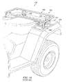
- FIGS. 14 , 15 and 16 illustrate conventional carrier racks having various configurations.
- FIG. 14 illustrates a conventional carrier rack 212 that is attached to a front fender assembly 224 of an all terrain vehicle 210.
- the carrier rack 212 includes a tubular frame member 240 that defines an outer perimeter of the carrier rack 212.
- FIG. 15 illustrates a conventional carrier rack 312 that is attached to a front fender assembly 324 of all terrain vehicle 310.
- the carrier rack 312 includes a tubular frame member 340 that defines an outer perimeter of the carrier rack 312.
- FIG. 16 illustrates a carrier rack 412 that includes a base 413 that is attached to a rear fender assembly 426 of an all terrain vehicle 410.
- the carrier rack 412 includes a pair of rear mount assemblies 465 that are bolted (using fasteners not shown) to the base 413 and are secured at an upper end to a tubular frame member 440.
- Carrier rack 412 includes a pair of strapping members 480 that are welded to the forward ends of opposite side portions of the tubular frame member 440, with the forward ends of the tubular frame member 440 being supported by base 413.
- the strapping members 480 are generally vertically extending.
- Each of the strapping members 480 is a solid rod and has a substantially uniform shape throughout its length.
- a carrier rack for a vehicle includes a tubular frame member and a plurality of strapping members.
- the tubular frame member includes at least four corner portions and defines an outer perimeter of the carrier rack. Each of the corner portions partially defines the outer perimeter.
- Each of the strapping members includes a first end portion, a second end portion and a tubular portion intermediate the first and second end portions. Each of the strapping members is secured, at each of the first and second end portions, to a respective one of the corner portions of the tubular frame member and is positioned entirely interior of the outer perimeter of the carrier rack. Each of the strapping members cooperates with the respective one of the corner portions of the tubular frame member to define a corner opening.
- the tubular frame member defines a carrier plane. Each of the strapping members is spaced apart from the carrier plane.
- the carrier plane is generally horizontally oriented, and each of the strapping members is below the carrier plane, when the carrier rack is attached to a vehicle and oriented to carry objects.
- a vehicle that includes a frame, a body structure supported by the frame, and a carrier rack supported by at least one of the frame and the body structure.
- the carrier rack includes a tubular frame member and a plurality of strapping members.
- the tubular frame member includes at least four corner portions and defines an outer perimeter of the carrier rack. Each of the corner portions partially defines the outer perimeter.
- Each of the strapping members includes a first end portion, a second end portion and a tubular portion intermediate the first and second end portions.
- Each of the strapping members is secured, at each of the first and second end portions, to a respective one of the corner portions of the tubular frame member and is positioned entirely interior of the outer perimeter of the carrier rack.
- Each of the strapping members cooperates with the respective one of the corner portions of the tubular frame member to define a corner opening.
- the tubular frame member defines a carrier plane.
- the carrier plane is generally horizontally oriented, and each of the strapping members is below the carrier plane.
- a saddle-type vehicle includes a frame, at least one rotatable front wheel coupled to the frame, at least one rotatable rear wheel coupled to the frame, a source of motive power, a body structure and a carrier rack.
- the source of motive power is supported by the frame and coupled to at least one of the front and rear wheels.
- the body structure is supported by the frame and includes a fender assembly.
- the fender assembly is adjacent to at least one of the front and rear wheels.
- the carrier rack is supported by at least one of the frame and the body structure and is adjacent to the fender assembly.
- the carrier rack includes a tubular frame member and a plurality of strapping members.
- the tubular frame member includes at least four corner portions and defines an outer perimeter of the carrier rack.
- Each of the corner portions partially defines the outer perimeter.
- Each of the strapping members is generally straight and includes a first end portion, a second end portion and a tubular portion intermediate the first and second end portions. The first end portion and the second end portion of each of the strapping members is welded to a respective one of the corner portions of the tubular frame member and is positioned entirely interior of the outer perimeter of the carrier rack. Each of the strapping members cooperates with the respective one of the corner portions of the tubular frame member to define a corner opening.
- the tubular frame member defines a carrier plane and a lower plane. The carrier plane is generally horizontally oriented and each of the strapping members is below the carrier plane and above the lower plane.
- Each of the strapping members further includes a longitudinal axis.
- a maximum distance between the longitudinal axis and the respective corner portion, as measured in a direction substantially perpendicular to the longitudinal axis ranges from about 19 mm to about 35 mm.
- the tubular frame member includes a first outside cross-sectional dimension.
- the tubular portion of each of the strapping members includes a second outside cross-sectional dimension.
- a ratio of the first outside cross-sectional dimension to the second outside cross-sectional dimension ranges from about 1.5 to about 2.0.
- the tubular frame member has a first generally circular cross-sectional shape and includes a first annular wall defining a first hollow interior.
- the first annular wall has a first thickness.
- the tubular portion of each of the strapping members has a second generally circular cross-sectional shape and includes a second annular wall defining a second hollow interior.
- the second annular wall has a second thickness.
- the first outside cross-sectional dimension is an outside diameter of the tubular frame member and, for each of the strapping members, the second outside cross-sectional dimension is an outside diameter of the tubular portion.
- the first end portion of each of the strapping members has a first distal height.
- the second end portion of each of the strapping members has a second distal height. For each of the strapping members, each of the first distal height and the second distal height is less than the second outside cross-sectional dimension.
- a ratio of the first thickness of the first annular wall of the tubular frame member to the first distal height ranges from about 0.5 to about 0.7.
- a ratio of the first thickness of the first annular wall of the tubular frame member to the second distal height ranges from about 0.5 to about 0.7.
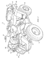
- FIGS. 1 and 2 illustrate a vehicle 10 that includes a carrier rack 12 according to one embodiment and further includes a carrier rack 112 according to another embodiment.
- Carrier racks according to the inventive principles can be used with a saddle-type vehicle such as vehicle 10, which is shown to be an ATV in FIGS. 1 and 2 , or with a variety of other land, water, or other vehicles.
- Vehicle 10 can include two rotatable front wheels 14 and two rotatable rear wheels 16 (one shown).
- the front wheels 14 and rear wheels 16 can be suspended from a frame 18 and are coupled to frame 18.
- the front wheels 14 can be suspended from frame 18 using a variety of conventional suspension systems, such as suspension system 20 shown partially in FIGS. 1 and 2 .
- Vehicle 10 can further include a source of motive power (illustrated generally at 21 in FIGS. 1 and 2 ), which can be an internal combustion engine and/or an electric motor or any other suitable source of motive power.
- the source of motive power can be coupled to the front wheels 14 and/or the rear wheels 16.
- the source of motive power can be drivingly connected to a drive train (not shown) that is operable for transferring torque to the front wheels 14 and/or the rear wheels 16.
- Vehicle 10 can also include a body 22 that can be supported by frame 18.
- the body 22 can include a front fender assembly 24 and a rear fender assembly 26.
- the front fender assembly 24 can be adjacent to and at least partially cover each of the front wheels 14, and the rear fender assembly 26 can be adjacent to and at least partially cover each of the rear wheels 16.
- Vehicle 10 can further include a handlebar assembly 30 coupled to the front wheels 14, which can be used by an operator of vehicle 10 to steer the front wheels 14.
- Vehicle 10 can further include a seat 32 that can be used to support an operator of vehicle 10.
- the carrier rack 12 can be supported by frame 18 and/or the rear fender assembly 26 and can be positioned adjacent the rear fender assembly 26 as shown in FIGS. 1 and 2 .
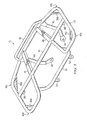
- the carrier rack 12 can include a tubular frame member 40 that defines an outer perimeter P 1 ( FIG. 4 ) of the carrier rack 12.
- Tubular frame member 40 can include a plurality of corner portions.
- the tubular frame member 40 can include four corner portions, which are designated 42a, 42b, 42c and 42d in FIGS. 3 and 4 .
- Each of the corner portions 42a, 42b, 42c and 42d can partially define the outer perimeter P 1 .
- Carrier rack 12 can also include other members, that can be tubular members having various cross-sectional shapes, which are interconnected with one another and with the tubular frame member 40.
- carrier rack 12 can include a tubular cross member 44 that extends laterally between opposite side portions of the tubular frame member 40.
- Each end of the tubular cross member 44 can be secured to the tubular frame member 40 by conventional means.
- each end of the tubular cross member 44 can be welded to the tubular frame member 40.
- Carrier rack 12 can also include generally longitudinally extending members 46 and 48, which can be tubular members, with one end of each of the generally longitudinally extending members 46, 48 being secured, for example by welding, to the tubular frame member 40, and the opposite end of each of the generally longitudinal extending members 46, 48 being secured, for example by welding, to the tubular cross member 44.
- generally longitudinally extending members 46 and 48 can be tubular members, with one end of each of the generally longitudinally extending members 46, 48 being secured, for example by welding, to the tubular frame member 40, and the opposite end of each of the generally longitudinal extending members 46, 48 being secured, for example by welding, to the tubular cross member 44.
- a laterally extending rear tubular member 50 can be secured at opposite ends to the tubular frame member 40, for example by welding, and can extend above the tubular frame member 40 as shown in FIGS. 1 , 3 and 5 .
- the rear tubular member 50 can act as a stop to facilitate preventing cargo carried by the carrier rack 12 from moving rearward off of the carrier rack 12.
- Carrier rack 12 can also include a generally laterally extending, forward tubular cross member 52, with each end of the cross member 52 being secured, for example by welding, to the tubular frame member 40.
- the forward tubular cross member 52 can extend downwardly from the tubular frame member 40 as shown in FIGS. 3 and 5 .
- a pair of mount brackets 54 can be secured to the forward tubular cross member 52 and can be used to attach the carrier rack 12 to the body 22 and/or the frame 18 of vehicle 10.
- brackets 54 can be used to attach the carrier rack 12 to the rear fender assembly 26 or to the frame 18 of the vehicle 10. This can be achieved in any suitable manner.
- conventional male fasteners can extend through apertures defined by mount brackets 54 and through apertures defined by mating mount brackets (not shown) secured to the rear fender assembly 26 and/or frame 18, and can be secured with conventional female fasteners.
- the male fasteners can be threaded into a structure that is part of, or integral with, the rear fender assembly 26 or frame 18 and includes mating internal threads.
- Carrier rack 12 can also include rear mount arms 60 and 62 which can be secured at one end, for example by welding, to the tubular frame member 40 and can extend downwardly from the tubular frame member 40.
- the mount arms 60 and 62 can terminate in distal eyelets 64 and 66, respectively.
- the distal eyelets 64, 66 can also be used to attach carrier rack 12 to the rear fender assembly 26 and/or frame 18.
- each distal eyelet 64, 66 can define an aperture which can be sized and configured to receive a male fastener (not shown), which can also extend through an aperture defined by a mating bracket (not shown) secured to the rear fender assembly 26 and/or frame 18, with the male fastener secured by a conventional female fastener such as a nut.
- a pair of spacers 68 can be secured to, and may extend downwardly from, the tubular cross member 44. Each spacer 68 can engage and/or be secured to the rear fender assembly 26 and/or frame 18.
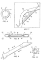
- the tubular frame member 40 can be made from round tubing, such that the tubular frame member 40 has a generally circular cross-sectional shape, as shown in FIG. 6 .
- tubular frame members can be provided that are made from tubes having other cross-sectional shapes, such as square or rectangular cross-sectional shapes.
- Tubular frame member 40 can include an outside cross-sectional dimension, which, in the embodiment shown in FIG. 6 , is an outside diameter d 1 of the tubular frame member 40.
- the tubular frame member 40 can include an annular wall 70 that defines a hollow interior 72 and has a thickness t 1 .
- the outside diameter d 1 of the tubular frame member 40 can range from about 20 mm to about 24 mm.
- the outside diameter d 1 can be about 22.2 mm.
- the thickness t 1 of the annular wall 70 can range from about 1.2 mm to about 1.6 mm. In one embodiment, the thickness t 1 can be about 1.4 mm.
- the carrier rack 12 can include a plurality of strapping members 80 (one shown in FIG. 9 ). Each of the strapping members 80 can be secured to a respective one of the corner portions of the tubular frame member 40 at a position that is entirely interior of the outer perimeter P 1 of carrier rack 12, as shown for example in FIG. 4 .
- a first one of the strapping members 80, designated 80a can be secured to the corner portion 42a of the tubular frame member 40
- a second one of the strapping members 80, designated 80b can be secured to the corner portion 42b
- a third one of the strapping members 80, designated 80c can be secured to the corner portion 42c
- a fourth one of the strapping members 80, designated 80d can be secured to the corner portion 42d.
- each of the strapping members 80 can include a first end portion 82, a second end portion 84, and a tubular portion 86 intermediate the first and second end portions 82, 84 and integral with each of the first and second end portions 82, 84.
- the first and second end portions 82, 84 and the tubular portion 86 can be made as a unitary structure.
- the tubular portion 86 of each strapping member 80 can have a generally circular cross-sectional shape and can include an outside cross-sectional dimension, which can be an outside diameter d 2 of the tubular portion 86 of strapping member 80.
- the tubular portion 86 of strapping member 80 can include an annular wall 88 that defines a hollow interior 90 and has a thickness t 2 .
- the outside diameter d 2 of the tubular portion 86 of strapping member 80 can range from about 10.0 mm to about 14.0 mm. In another embodiment, the outside diameter d 2 can be about 12.0 mm.
- the thickness t 2 of the annular wall 88 can range from about 1.0 mm to about 1.4 mm. In another embodiment, the thickness t 2 can be about 1.2 mm.
- each strapping member 80 can be secured to a respective corner portion of the tubular frame member 40.
- the first end portion 82 and second end portion 84 of the strapping member 80c can be secured to the corner portion 42c of the tubular frame member 40.
- the first end portion 82 and the second end portion 84 can each be welded to the corner portion 42c. In order to facilitate welding each of the strapping members 80 to the respective corner portion, such as corner portion 42c shown in FIGS.
- each of the first and second end portions 82, 84 can be crimped or stamped, such that a distal end of each of the end portions is substantially flattened and has a distal height that is less than the outside diameter d 2 of the tubular portion 86 of strapping member 80.
- the first end portion 82 of each strapping member 80 can have a distal height h 1 (shown in FIG. 8 with respect to strapping member 80c) that is smaller than the outside diameter d 2 ( FIG. 10 ) of the tubular portion 86 of strapping member 80.
- the second end portion 84 of each strapping member 80 can have a distal height h 2 (shown in FIG. 8 with respect to strapping member 80c) which is smaller than the outside diameter d 2 of the tubular portion 86 of strapping member 80.
- a distal end surface of each of the end portions 82, 84 can be elongated and substantially flat, as shown in FIG. 9 with respect to a distal end surface 83 of the end portion 82.
- the configuration of the distal end surface of end portion 84 in cooperation with distal height h 2 which is less than the outside diameter d 1 of the tubular frame member 40, facilitates efficient welding of the end portion 84 of each strapping member 80 to the respective corner portion of the tubular frame member 40, such as corner portion 42c shown in FIGS. 7 and 8 .
- the substantially flat distal end surface 83 of the end portion 82 and the substantially flat distal end surface of the end portion 84 improve the strength of the associated welds as compared to the weld strength that can be achieved when welding a wire or solid rod to a tubular member.
- each strapping member 80 can have a longitudinal axis 92.
- the strapping member 80 can be sized such that a maximum distance 94 between the tubular portion 86 and the respective corner portion, such as corner portion 42c shown in FIG. 7 , as measured in a direction substantially perpendicular to the longitudinal axis 92, ranges from about 19 mm to about 35 mm.
- the range in magnitude of the maximum distance 94 permits a conventional hook, clasp or the like, that is attached at one end to a tie-down member such as a strap, cord, or the like, to engage and be releasably secured to the strapping member 80.
- a tie-down member such as a strap, cord, or the like
- tie-down members 95 can be used to secure cargo 96 to the carrier rack 12.
- Cargo 96 can be a box as shown in FIG. 2 or any of a wide variety of other items.
- Each tie-down member 95 can include a strap 97 and a pair of generally S-shaped hooks 98, with one of the hooks 98 being secured to each end of the strap 97.
- Each hook 98 can be releasably secured to one of the strapping members 80.
- the tubular frame member 40 can cooperate with the tubular cross member 44 and the generally longitudinally extending members 46, 48 to define an upper support surface of carrier rack 12 that is suitable for supporting cargo, such as cargo 96 shown in FIG. 2 .
- the overall lengths of the strapping members 80 can vary as required, depending upon the configuration of the respective one of the corner portions 42a, 42b, 42c and 42d to which the respective strapping members are secured, to maintain the desired maximum distance 94 between the tubular portion 86 of each strapping member 80 and the respective one of the corner portions 42a, 42b, 42c and 42d.
- the length of the strapping member 80c can be greater than the length of strapping member 80d, due to the differences in configurations of corner portion 42c, to which strapping member 80c is secured, and corner portion 42d, to which strapping member 80d is secured.
- the angle between the distal end surface 83 of the distal end portion 82 and the longitudinal axis 92 can be the same as or different than the angle between the distal end surface of the distal end portion 84 and the longitudinal axis 92, for any of the strapping members 80, and that these angles can vary among the strapping members 80, depending upon the configurations of the corner portions 42a, 42b, 42c and 42d.
- An upper surface of the tubular frame member 40 can define a carrier plane 100 ( FIG. 8 ).
- Each strapping member 80 can be sized and secured to the respective one of the corner portions 42a, 42b, 42c and 42d of the tubular frame member 40 such that each of the strapping members 80 is spaced apart from the carrier plane 100.
- the carrier plane 100 can be generally horizontally oriented, and each of the strapping members 80 can be below the carrier plane 100, when the carrier rack 12 is attached to a vehicle, such as vehicle 10, and is oriented to carry objects, for example when the carrier rack 12 is oriented as shown in FIG. 2 .
- Each strapping member 80 can be sized so that both the strapping member 80 and a hook of a tie-down member, such as one of the hooks 98 of the tie-down member 95, are below the carrier plane 100 when the hook 98 is releasably secured to the strapping member 80.
- the outside diameter d 2 of the tubular portion 86 of strapping member 80 is shown to be smaller than the outside diameter d 1 of the tubular frame member 40. In one embodiment, a ratio of the outside diameter d 1 to the outside diameter d 2 ranges from about 1.5 to about 2.0. In another embodiment, the ratio of the outside diameter d 1 to the outside diameter d 2 ranges from about 1.6 to about 1.9.
- a ratio of the thickness t 1 of the annular wall 70 of the tubular frame member 40 to the distal height h 1 of the first end portion 82 of strapping member 80, and a ratio of the thickness t 1 of the annular wall 70 to the distal height h 2 of the second end portion 84 of strapping member 80 each ranges from about 0.5 to about 0.7.
- a lower surface of the tubular frame member 40 can define a lower plane 102 ( FIG. 8 ). As shown in FIG. 8 , with respect to strapping member 80c, each of the strapping members 80 can be spaced apart from the lower plane 102 and can be located between the lower plane 102 and the carrier plane 100.
- the lower plane 102 can be generally horizontally oriented and each of the strapping members 80 can be above the lower plane 102 when the carrier rack 12 is attached to a vehicle, such as vehicle 10, and is oriented to carry objects, for example when the carrier rack 12 is oriented as shown in FIG. 2 .
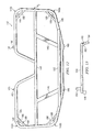
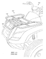
- FIGS. 11-13 further illustrate the carrier rack 112, which can be secured to and supported by front fender assembly 24 and/or frame 18.
- the carrier rack 112 can be positioned adjacent the front fender assembly 24 as shown in FIGS. 1 and 2 .
- the carrier rack 112 can include a tubular frame member 140 that defines an outer perimeter P 2 of the carrier rack 112.
- the tubular frame member 140 can include a plurality of corner portions.
- the tubular frame member 140 can include four corner portions, designated 142a, 142b, 142c, and 142d in FIGS. 11 and 12 .
- Each of the corner portions 142a, 142b, 142c and 142d can partially define the outer perimeter P 2 .
- the carrier rack 112 can also include other members, that can be tubular members having various cross-sectional shapes, which are interconnected with one another and with the tubular frame member 140,
- carrier rack 112 can include a tubular cross-member 144 that extends laterally between opposite side portions of the tubular frame member 140.
- Each end of the tubular cross member 144 can be secured to the tubular frame member by conventional means, such as welding.
- Carrier rack 112 can also include generally longitudinally extending members 146 and 148, which can be tubular members, with one end of each of the generally longitudinally extending members 146, 148 being secured, for example by welding, to the tubular frame member 140, and the opposite end of each of the generally longitudinally extending members 146, 148 being secured, for example by welding, to the tubular cross member 144.
- a laterally extending forward tubular member 150 can be secured at opposite ends to the tubular frame member 140, for example by welding, and can extend above the tubular frame member 140 as shown in FIGS. 11 and 13 .
- the forward tubular member 150 can act as a stop to facilitate preventing cargo carried by the carrier rack 112 from moving forward off of the carrier rack 112.
- Carrier rack 112 can also include rear mount arms 160, 162 that can terminate in distal eyelets 164, 166, respectively, that can be used to attach carrier rack 112 to the front fender assembly 24 and/or the frame 18.
- Carrier rack 112 can also include one or more spacers 168 (two shown) that can engage and/or be secured to a forward portion of the tubular frame member 140 and that can be used to secure carrier rack 112 to the front fender assembly 24 and/or frame 18.
- the carrier rack 112 can also include one or more spacers 169 that can be secured to tubular frame member 140 and that can engage and/or can be secured to the front fender assembly 24 and/or frame 18.
- the tubular frame member 140 can be made from round tubing, such that the tubular frame member has a generally circular cross-sectional shape. In other embodiments, tubular frame members can be provided that are made from tubes having other cross-sectional shapes, such as square or rectangular cross-sectional shapes.
- Tubular frame member 140 can include an outside cross-sectional dimension, which, in the embodiment shown in FIGS. 11-13 , is an outside diameter of the tubular frame member 140.
- the tubular frame member 140 can include an annular wall that defines a hollow interior, with the annular wall having a thickness. In one embodiment, the outside diameter of the tubular frame member 140 can range from about 17 mm to about 21 mm. In another embodiment, the outside diameter of the tubular frame member 140 can be about 19.1 mm. In one embodiment, the thickness of the annular wall of the tubular frame member 140 can range from about 1.2 mm to about 1.6 mm. In one embodiment, the wall thickness of the annular wall of the tubular frame member 140 can be about 1.4 mm.
- the carrier rack 112 can also include a plurality of strapping members 180, with each of the strapping members 180 being secured to a respective one of the corner portions 142a, 142b, 142c and 142d, of the tubular frame member 140.
- Each of the strapping members 180 can have the same, or a similar configuration as the configuration of the strapping member 80 of carrier rack 12.
- each of the strapping members 180 can have first and second end portions 182, 184, which can be stamped or crimped, and a tubular portion 186 intermediate and integral with the first and second end portions 182, 184.
- the tubular portion 186 of strapping member 180 can include an annular wall having a thickness, with the annular wall defining a hollow interior such that the tubular portion 186 has a generally circular cross-sectional shape.
- the thickness of the annular wall of the tubular portion 186 can range from about 1.0 mm to about 1.4 mm, and in another embodiment this thickness can be about 1.2 mm.
- Each strapping member 180 can have an outside cross-sectional dimension, which, in the embodiment shown in FIGS. 11-13 can be an outside diameter of the tubular portion 186 of the strapping member 180.
- the outside diameter of the tubular portion 186 of strapping member 180 can range from about 10.0 mm to about 14.0 mm. In another embodiment, the outside diameter of the tubular portion 186 of strapping member 180 can be about 12.0 mm.
- the outside diameter of the tubular portion 186 of strapping member 180 can be smaller than the outside diameter of the tubular frame member 140.
- a ratio of the outside diameter of the tubular frame member 140 to the outside diameter of the tubular portion 186 of strapping member 180 ranges from about 1.5 to about 2.0. In another embodiment, this ratio ranges from about 1.6 to about 1.9.
- a distal end surface of each of the end portions 182, 184 of the strapping member 180 can be elongated and substantially flat.
- Each strapping member 180 can be secured to the tubular frame member 140 such that the magnitude of a maximum distance between the tubular portion 186 of each strapping member 180 and the respective corner portion of the tubular frame member 140 ranges from about 19 mm to about 35 mm.
- This spacing permits the carrier rack 112 to accommodate conventional hooks, clasps, or the like, that are attached to tie-down members, such as straps, cords, or the like.
- tie-down members such as straps, cords, or the like.
- a pair of tie-down members 195 can be used to secure cargo 196, shown to be a sleeping bag, to carrier rack 112.
- Each tie-down member 195 can include a strap 197 and a pair of generally S-shaped hooks 198, with one of the hooks 198 being secured to each end of the strap 197.
- Each hook 198 can be releasably secured to one of the strapping members 180, which releasably secures cargo 190 to the carrier rack 112.
- a portion of each hook 198 can be disposed in a corner opening 199 defined by the associated strapping member 180 and the tubular frame member 140.
- the overall lengths of the strapping members 180, as well as the angular orientations of the distal end surfaces relative to the longitudinal axis of the respective strapping member 180, can vary as required depending upon the configuration of the respective one of the corner portions 142a, 142b, 142c and 142d, to which the strapping members are welded.
- An upper surface of the tubular frame member 140 defines a carrier plane.
- Each of the strapping members 180 can be sized and secured to the respective one of the corner portions of the tubular frame member 140 such that each of the strapping members 180 is spaced apart from the carrier plane.
- the carrier plane can be generally horizontally oriented and each of the strapping members 180 can be below the carrier plane, when the carrier rack 112 is attached to a vehicle, such as vehicle 10, and is oriented to carry objects, for example, when the carrier rack 112 is oriented as shown in FIG. 2 .
- a ratio of the thickness of the annular wall of the tubular frame member 140 to the distal height of either of the end portions of the strapping member 180 ranges from about 0.5 mm to about 0.7 mm.
- a lower surface of the tubular frame member 140 can define a lower plane.
- Each of the strapping members 180 can be spaced apart from the lower plane such that each of the strapping members 180 is between the carrier plane and the lower plane.
- the lower plane can be generally horizontally oriented and each of the strapping members 180 can be above the lower plane, when the carrier rack 112 is attached to a vehicle, such as vehicle 10, and is oriented to carry objects, for example, when the carrier rack 112 is oriented as shown in FIG. 2 .
- carrier racks as described above (e.g., 12, 112) can result in several advantages.
- the permissible variation in size of the cargo to be secured to the carrier rack is enhanced since the strapping members and the hooks of the tie-down members that are releasably secured to respective strapping members do not extend above the carrier plane defined by the upper surface of the tubular frame member of the rack, and accordingly do not typically interfere with or contact cargo resting upon the rack.
- the presence of the strapping members at each of four corners permits cargo of many different sizes, shapes and orientations to be strapped down, and from multiple directions.
- the tubular construction of the strapping members is light weight, for example as compared to solid rods of the same size, and produces the desired mechanical strength, which can be superior to the mechanical strength of the tie-down wires used on some conventional carrier racks.
- the stamped or crimped ends of the strapping members facilitates efficient and effective welding of the strapping members to the tubular frame member.
- the invention is directed to provide a carrier rack for a vehicle that includes a tubular frame member and a plurality of strapping members.
- the tubular frame member includes at least four corner portions and defines an outer perimeter of the carrier rack and also defines a carrier plane.
- Each of the strapping members is secured to a respective one of the corner portions, and is spaced apart from the carrier plane and positioned entirely interior of the outer perimeter of the carrier rack.
- the carrier plane is generally horizontally oriented, and each of the strapping members is below the carrier plane, when the carrier rack is attached to a vehicle and oriented to carry objects.
Landscapes
- Engineering & Computer Science (AREA)
- Mechanical Engineering (AREA)
- Automatic Cycles, And Cycles In General (AREA)
- Fittings On The Vehicle Exterior For Carrying Loads, And Devices For Holding Or Mounting Articles (AREA)
- Body Structure For Vehicles (AREA)
- Packaging Of Machine Parts And Wound Products (AREA)
Applications Claiming Priority (1)
| Application Number | Priority Date | Filing Date | Title |
|---|---|---|---|
| US12/473,430 US8096582B2 (en) | 2009-05-28 | 2009-05-28 | Carrier rack |
Publications (3)
| Publication Number | Publication Date |
|---|---|
| EP2255999A2 true EP2255999A2 (de) | 2010-12-01 |
| EP2255999A3 EP2255999A3 (de) | 2011-02-23 |
| EP2255999B1 EP2255999B1 (de) | 2011-12-07 |
Family
ID=42557508
Family Applications (1)
| Application Number | Title | Priority Date | Filing Date |
|---|---|---|---|
| EP10160572A Not-in-force EP2255999B1 (de) | 2009-05-28 | 2010-04-21 | Gepäckträger |
Country Status (5)
| Country | Link |
|---|---|
| US (1) | US8096582B2 (de) |
| EP (1) | EP2255999B1 (de) |
| CN (1) | CN101898596B (de) |
| AT (1) | ATE536282T1 (de) |
| AU (1) | AU2010201556B2 (de) |
Cited By (1)
| Publication number | Priority date | Publication date | Assignee | Title |
|---|---|---|---|---|
| CN118850229A (zh) * | 2024-09-20 | 2024-10-29 | 浙江永途动力科技有限公司 | 智能捆绑监控多功能踏板全地形运输车 |
Families Citing this family (7)
| Publication number | Priority date | Publication date | Assignee | Title |
|---|---|---|---|---|
| JP5597528B2 (ja) * | 2010-12-24 | 2014-10-01 | 川崎重工業株式会社 | 荷掛け装置 |
| US8925965B2 (en) * | 2011-03-18 | 2015-01-06 | Louis G Pecora | Utility tray |
| USD713775S1 (en) | 2013-03-15 | 2014-09-23 | James H. Lagermann | Utility task vehicle rack |
| US9168875B2 (en) * | 2014-01-16 | 2015-10-27 | Bradley Haler | Quick release ATV rack system |
| IT201600068660A1 (it) * | 2016-07-01 | 2018-01-01 | Piaggio & C Spa | Portapacchi anteriore per un motociclo con scocca portante |
| US10569819B2 (en) * | 2016-07-08 | 2020-02-25 | Polaris Industries Inc. | All-terrain vehicle |
| US10486610B1 (en) * | 2018-05-01 | 2019-11-26 | Jerry Owens | Vehicle carrier rack |
Family Cites Families (23)
| Publication number | Priority date | Publication date | Assignee | Title |
|---|---|---|---|---|
| GB415519A (en) | 1933-04-07 | 1934-08-30 | Cranford Mfg Company Ltd | Improvements in, and in the manufacture of production of, luggagecarriers for attachment to cycles |
| US4176771A (en) * | 1978-01-09 | 1979-12-04 | Dubroc Tyrone P | Carrier for three-wheel motorcycle |
| USD364140S (en) * | 1994-05-16 | 1995-11-14 | Gustavsen Gilbert E | Rear accessory rack for recreational vehicle |
| USD363267S (en) * | 1994-05-16 | 1995-10-17 | Gustavsen Gilbert E | Front accessory rack for recreational vehicle |
| US6016943A (en) * | 1995-09-29 | 2000-01-25 | Polaris Industries Inc. | Injection molded racks and components for off-road recreational and utility vehicles |
| US5636885A (en) * | 1996-05-16 | 1997-06-10 | Hummel; Jakie | Combination automobile grill guard and tow hitch |
| AU721168B2 (en) * | 1996-06-17 | 2000-06-22 | Malcolm Robert Burke | Vehicle racking system |
| US5842732A (en) * | 1996-11-27 | 1998-12-01 | Daggett, Deceased; Bill E. | Riding lawn mower canopy |
| CH692498A5 (de) * | 1998-01-29 | 2002-07-15 | Pletscher Geb | Lasttragkörper für einen Gepäckträger. |
| US6394326B1 (en) * | 2000-11-10 | 2002-05-28 | Gene A. Lanier | Bicycle rack for trucks |
| US6484914B1 (en) * | 2001-08-17 | 2002-11-26 | Barry A. Willey | Motorcycle accessory mounting system |
| CN2521122Y (zh) * | 2001-12-27 | 2002-11-20 | 王志骅 | 机车载货两用文武架 |
| US7854460B2 (en) * | 2002-06-13 | 2010-12-21 | Arctic Cat Inc. | Mating receiver rack for personal recreational vehicles |
| US7044526B2 (en) * | 2002-06-13 | 2006-05-16 | Arctic Cat Inc. | Mating receiver rack for personal recreational vehicles |
| US7165702B1 (en) * | 2003-10-15 | 2007-01-23 | Polaris Industries, Inc. | Cargo mount system for utility vehicles |
| US20050180835A1 (en) * | 2004-02-18 | 2005-08-18 | Schneider Brian D. | Tie down harness |
| US20050205628A1 (en) * | 2004-03-18 | 2005-09-22 | Lehmann Bret A | Repositionable carrier rack assembly for an all terrain vehicle (ATV) |
| US20060054648A1 (en) * | 2004-09-16 | 2006-03-16 | Maguire Donald J | Carrier rack for a four-wheeler |
| JP4627225B2 (ja) * | 2005-06-30 | 2011-02-09 | 本田技研工業株式会社 | 車両用キャリア |
| US20070045368A1 (en) * | 2005-09-01 | 2007-03-01 | Lavelle Charles C | Vehicle carrier rack utilizing a grid system for mounting accessories and load blocks |
| US20070175937A1 (en) * | 2006-02-01 | 2007-08-02 | Craig Caldwell | Foldable carrier rack for all terrain vehicles and method |
| JP4945795B2 (ja) * | 2007-04-09 | 2012-06-06 | 壽友 植田 | ショピングカートと、大型バスケットを装着出来る自転車 |
| USD606905S1 (en) * | 2009-02-13 | 2009-12-29 | Loncin Industry Co., Ltd. | All terrain vehicle |
-
2009
- 2009-05-28 US US12/473,430 patent/US8096582B2/en not_active Expired - Fee Related
-
2010
- 2010-04-19 AU AU2010201556A patent/AU2010201556B2/en not_active Ceased
- 2010-04-21 AT AT10160572T patent/ATE536282T1/de active
- 2010-04-21 EP EP10160572A patent/EP2255999B1/de not_active Not-in-force
- 2010-05-20 CN CN201010183502.4A patent/CN101898596B/zh not_active Expired - Fee Related
Non-Patent Citations (1)
| Title |
|---|
| None |
Cited By (1)
| Publication number | Priority date | Publication date | Assignee | Title |
|---|---|---|---|---|
| CN118850229A (zh) * | 2024-09-20 | 2024-10-29 | 浙江永途动力科技有限公司 | 智能捆绑监控多功能踏板全地形运输车 |
Also Published As
| Publication number | Publication date |
|---|---|
| AU2010201556A1 (en) | 2010-12-16 |
| US20100301592A1 (en) | 2010-12-02 |
| AU2010201556B2 (en) | 2011-04-28 |
| EP2255999A3 (de) | 2011-02-23 |
| EP2255999B1 (de) | 2011-12-07 |
| CN101898596A (zh) | 2010-12-01 |
| ATE536282T1 (de) | 2011-12-15 |
| CN101898596B (zh) | 2013-03-13 |
| US8096582B2 (en) | 2012-01-17 |
Similar Documents
| Publication | Publication Date | Title |
|---|---|---|
| EP2255999B1 (de) | Gepäckträger | |
| US11325453B2 (en) | Battery mounting bracket for heavy duty vehicle | |
| US9333822B1 (en) | Trailer hitch attachment system with multiple receivers | |
| US6752303B2 (en) | Carrier device | |
| US7641251B1 (en) | Collapsible truck rack and method of use | |
| US5497927A (en) | Bicycle rack | |
| US3176903A (en) | Two-wheeled vehicle carrier | |
| US8066305B2 (en) | Adjustable fender | |
| US5476203A (en) | Bicycle crank shaft support carrier | |
| US20110133438A1 (en) | Utility Vehicle Module | |
| US20040144908A1 (en) | Telescopically adjustable battery holddown | |
| US7975888B2 (en) | Rear-mounted bicycle carrier with stabilizing structures | |
| US20110259931A1 (en) | Auxiliary rack for an ATV | |
| US20170057419A1 (en) | Bicycle Carrier and Method for Serially Loading Bicycles Thereon | |
| US7736105B2 (en) | Pickup truck window, bed, and cab protector | |
| US20130280003A1 (en) | Vehicle chock assembly and method | |
| JP4011092B2 (ja) | 車両用吊上げ具 | |
| US20110139845A1 (en) | Tree stand transporter | |
| US20220379823A1 (en) | Tractor tool caddy | |
| US7922051B2 (en) | Apparatus for transporting bicycles and method of use | |
| JP3797724B2 (ja) | 自動車用車輪運搬保持装置 | |
| CN212556579U (zh) | 转运车 | |
| JP6227430B2 (ja) | 牽引リヤカーの牽引車への連結構造 | |
| JP2571443Y2 (ja) | 搬送物載置用パレット | |
| US12508854B2 (en) | Truck towing system |
Legal Events
| Date | Code | Title | Description |
|---|---|---|---|
| PUAI | Public reference made under article 153(3) epc to a published international application that has entered the european phase |
Free format text: ORIGINAL CODE: 0009012 |
|
| 17P | Request for examination filed |
Effective date: 20100421 |
|
| AK | Designated contracting states |
Kind code of ref document: A2 Designated state(s): AT BE BG CH CY CZ DE DK EE ES FI FR GB GR HR HU IE IS IT LI LT LU LV MC MK MT NL NO PL PT RO SE SI SK SM TR |
|
| AX | Request for extension of the european patent |
Extension state: AL BA ME RS |
|
| PUAL | Search report despatched |
Free format text: ORIGINAL CODE: 0009013 |
|
| AK | Designated contracting states |
Kind code of ref document: A3 Designated state(s): AT BE BG CH CY CZ DE DK EE ES FI FR GB GR HR HU IE IS IT LI LT LU LV MC MK MT NL NO PL PT RO SE SI SK SM TR |
|
| AX | Request for extension of the european patent |
Extension state: AL BA ME RS |
|
| RIC1 | Information provided on ipc code assigned before grant |
Ipc: B62J 7/08 20060101ALI20110117BHEP Ipc: B60R 9/10 20060101ALI20110117BHEP Ipc: B60R 9/06 20060101AFI20100924BHEP |
|
| GRAP | Despatch of communication of intention to grant a patent |
Free format text: ORIGINAL CODE: EPIDOSNIGR1 |
|
| RIC1 | Information provided on ipc code assigned before grant |
Ipc: B62J 7/08 20060101ALI20110608BHEP Ipc: B60R 9/10 20060101ALI20110608BHEP Ipc: B60R 9/06 20060101AFI20110608BHEP |
|
| GRAS | Grant fee paid |
Free format text: ORIGINAL CODE: EPIDOSNIGR3 |
|
| GRAA | (expected) grant |
Free format text: ORIGINAL CODE: 0009210 |
|
| AK | Designated contracting states |
Kind code of ref document: B1 Designated state(s): AT BE BG CH CY CZ DE DK EE ES FI FR GB GR HR HU IE IS IT LI LT LU LV MC MK MT NL NO PL PT RO SE SI SK SM TR |
|
| REG | Reference to a national code |
Ref country code: GB Ref legal event code: FG4D |
|
| REG | Reference to a national code |
Ref country code: CH Ref legal event code: EP |
|
| REG | Reference to a national code |
Ref country code: IE Ref legal event code: FG4D |
|
| REG | Reference to a national code |
Ref country code: DE Ref legal event code: R096 Ref document number: 602010000476 Country of ref document: DE Effective date: 20120223 |
|
| REG | Reference to a national code |
Ref country code: NL Ref legal event code: VDEP Effective date: 20111207 |
|
| PG25 | Lapsed in a contracting state [announced via postgrant information from national office to epo] |
Ref country code: LT Free format text: LAPSE BECAUSE OF FAILURE TO SUBMIT A TRANSLATION OF THE DESCRIPTION OR TO PAY THE FEE WITHIN THE PRESCRIBED TIME-LIMIT Effective date: 20111207 Ref country code: NO Free format text: LAPSE BECAUSE OF FAILURE TO SUBMIT A TRANSLATION OF THE DESCRIPTION OR TO PAY THE FEE WITHIN THE PRESCRIBED TIME-LIMIT Effective date: 20120307 |
|
| LTIE | Lt: invalidation of european patent or patent extension |
Effective date: 20111207 |
|
| PG25 | Lapsed in a contracting state [announced via postgrant information from national office to epo] |
Ref country code: GR Free format text: LAPSE BECAUSE OF FAILURE TO SUBMIT A TRANSLATION OF THE DESCRIPTION OR TO PAY THE FEE WITHIN THE PRESCRIBED TIME-LIMIT Effective date: 20120308 Ref country code: LV Free format text: LAPSE BECAUSE OF FAILURE TO SUBMIT A TRANSLATION OF THE DESCRIPTION OR TO PAY THE FEE WITHIN THE PRESCRIBED TIME-LIMIT Effective date: 20111207 Ref country code: SI Free format text: LAPSE BECAUSE OF FAILURE TO SUBMIT A TRANSLATION OF THE DESCRIPTION OR TO PAY THE FEE WITHIN THE PRESCRIBED TIME-LIMIT Effective date: 20111207 Ref country code: NL Free format text: LAPSE BECAUSE OF FAILURE TO SUBMIT A TRANSLATION OF THE DESCRIPTION OR TO PAY THE FEE WITHIN THE PRESCRIBED TIME-LIMIT Effective date: 20111207 Ref country code: SE Free format text: LAPSE BECAUSE OF FAILURE TO SUBMIT A TRANSLATION OF THE DESCRIPTION OR TO PAY THE FEE WITHIN THE PRESCRIBED TIME-LIMIT Effective date: 20111207 Ref country code: HR Free format text: LAPSE BECAUSE OF FAILURE TO SUBMIT A TRANSLATION OF THE DESCRIPTION OR TO PAY THE FEE WITHIN THE PRESCRIBED TIME-LIMIT Effective date: 20111207 |
|
| PG25 | Lapsed in a contracting state [announced via postgrant information from national office to epo] |
Ref country code: CY Free format text: LAPSE BECAUSE OF FAILURE TO SUBMIT A TRANSLATION OF THE DESCRIPTION OR TO PAY THE FEE WITHIN THE PRESCRIBED TIME-LIMIT Effective date: 20111207 Ref country code: BE Free format text: LAPSE BECAUSE OF FAILURE TO SUBMIT A TRANSLATION OF THE DESCRIPTION OR TO PAY THE FEE WITHIN THE PRESCRIBED TIME-LIMIT Effective date: 20111207 |
|
| PG25 | Lapsed in a contracting state [announced via postgrant information from national office to epo] |
Ref country code: BG Free format text: LAPSE BECAUSE OF FAILURE TO SUBMIT A TRANSLATION OF THE DESCRIPTION OR TO PAY THE FEE WITHIN THE PRESCRIBED TIME-LIMIT Effective date: 20120307 Ref country code: EE Free format text: LAPSE BECAUSE OF FAILURE TO SUBMIT A TRANSLATION OF THE DESCRIPTION OR TO PAY THE FEE WITHIN THE PRESCRIBED TIME-LIMIT Effective date: 20111207 Ref country code: SK Free format text: LAPSE BECAUSE OF FAILURE TO SUBMIT A TRANSLATION OF THE DESCRIPTION OR TO PAY THE FEE WITHIN THE PRESCRIBED TIME-LIMIT Effective date: 20111207 Ref country code: IS Free format text: LAPSE BECAUSE OF FAILURE TO SUBMIT A TRANSLATION OF THE DESCRIPTION OR TO PAY THE FEE WITHIN THE PRESCRIBED TIME-LIMIT Effective date: 20120407 Ref country code: CZ Free format text: LAPSE BECAUSE OF FAILURE TO SUBMIT A TRANSLATION OF THE DESCRIPTION OR TO PAY THE FEE WITHIN THE PRESCRIBED TIME-LIMIT Effective date: 20111207 |
|
| PG25 | Lapsed in a contracting state [announced via postgrant information from national office to epo] |
Ref country code: RO Free format text: LAPSE BECAUSE OF FAILURE TO SUBMIT A TRANSLATION OF THE DESCRIPTION OR TO PAY THE FEE WITHIN THE PRESCRIBED TIME-LIMIT Effective date: 20111207 Ref country code: PT Free format text: LAPSE BECAUSE OF FAILURE TO SUBMIT A TRANSLATION OF THE DESCRIPTION OR TO PAY THE FEE WITHIN THE PRESCRIBED TIME-LIMIT Effective date: 20120409 Ref country code: PL Free format text: LAPSE BECAUSE OF FAILURE TO SUBMIT A TRANSLATION OF THE DESCRIPTION OR TO PAY THE FEE WITHIN THE PRESCRIBED TIME-LIMIT Effective date: 20111207 |
|
| REG | Reference to a national code |
Ref country code: AT Ref legal event code: MK05 Ref document number: 536282 Country of ref document: AT Kind code of ref document: T Effective date: 20111207 |
|
| PLBE | No opposition filed within time limit |
Free format text: ORIGINAL CODE: 0009261 |
|
| STAA | Information on the status of an ep patent application or granted ep patent |
Free format text: STATUS: NO OPPOSITION FILED WITHIN TIME LIMIT |
|
| PG25 | Lapsed in a contracting state [announced via postgrant information from national office to epo] |
Ref country code: DK Free format text: LAPSE BECAUSE OF FAILURE TO SUBMIT A TRANSLATION OF THE DESCRIPTION OR TO PAY THE FEE WITHIN THE PRESCRIBED TIME-LIMIT Effective date: 20111207 |
|
| REG | Reference to a national code |
Ref country code: DE Ref legal event code: R119 Ref document number: 602010000476 Country of ref document: DE |
|
| 26N | No opposition filed |
Effective date: 20120910 |
|
| PG25 | Lapsed in a contracting state [announced via postgrant information from national office to epo] |
Ref country code: IT Free format text: LAPSE BECAUSE OF FAILURE TO SUBMIT A TRANSLATION OF THE DESCRIPTION OR TO PAY THE FEE WITHIN THE PRESCRIBED TIME-LIMIT Effective date: 20111207 Ref country code: MC Free format text: LAPSE BECAUSE OF NON-PAYMENT OF DUE FEES Effective date: 20120430 |
|
| REG | Reference to a national code |
Ref country code: DE Ref legal event code: R097 Ref document number: 602010000476 Country of ref document: DE Effective date: 20120910 |
|
| REG | Reference to a national code |
Ref country code: IE Ref legal event code: MM4A |
|
| REG | Reference to a national code |
Ref country code: FR Ref legal event code: ST Effective date: 20121228 |
|
| PG25 | Lapsed in a contracting state [announced via postgrant information from national office to epo] |
Ref country code: AT Free format text: LAPSE BECAUSE OF FAILURE TO SUBMIT A TRANSLATION OF THE DESCRIPTION OR TO PAY THE FEE WITHIN THE PRESCRIBED TIME-LIMIT Effective date: 20111207 Ref country code: IE Free format text: LAPSE BECAUSE OF NON-PAYMENT OF DUE FEES Effective date: 20120421 |
|
| REG | Reference to a national code |
Ref country code: DE Ref legal event code: R119 Ref document number: 602010000476 Country of ref document: DE Effective date: 20121101 |
|
| PG25 | Lapsed in a contracting state [announced via postgrant information from national office to epo] |
Ref country code: FR Free format text: LAPSE BECAUSE OF NON-PAYMENT OF DUE FEES Effective date: 20120430 Ref country code: MK Free format text: LAPSE BECAUSE OF FAILURE TO SUBMIT A TRANSLATION OF THE DESCRIPTION OR TO PAY THE FEE WITHIN THE PRESCRIBED TIME-LIMIT Effective date: 20111207 |
|
| PG25 | Lapsed in a contracting state [announced via postgrant information from national office to epo] |
Ref country code: ES Free format text: LAPSE BECAUSE OF FAILURE TO SUBMIT A TRANSLATION OF THE DESCRIPTION OR TO PAY THE FEE WITHIN THE PRESCRIBED TIME-LIMIT Effective date: 20120318 |
|
| PG25 | Lapsed in a contracting state [announced via postgrant information from national office to epo] |
Ref country code: FI Free format text: LAPSE BECAUSE OF FAILURE TO SUBMIT A TRANSLATION OF THE DESCRIPTION OR TO PAY THE FEE WITHIN THE PRESCRIBED TIME-LIMIT Effective date: 20111207 |
|
| PG25 | Lapsed in a contracting state [announced via postgrant information from national office to epo] |
Ref country code: MT Free format text: LAPSE BECAUSE OF FAILURE TO SUBMIT A TRANSLATION OF THE DESCRIPTION OR TO PAY THE FEE WITHIN THE PRESCRIBED TIME-LIMIT Effective date: 20111207 |
|
| PG25 | Lapsed in a contracting state [announced via postgrant information from national office to epo] |
Ref country code: TR Free format text: LAPSE BECAUSE OF FAILURE TO SUBMIT A TRANSLATION OF THE DESCRIPTION OR TO PAY THE FEE WITHIN THE PRESCRIBED TIME-LIMIT Effective date: 20111207 |
|
| PG25 | Lapsed in a contracting state [announced via postgrant information from national office to epo] |
Ref country code: LU Free format text: LAPSE BECAUSE OF NON-PAYMENT OF DUE FEES Effective date: 20120421 Ref country code: SM Free format text: LAPSE BECAUSE OF FAILURE TO SUBMIT A TRANSLATION OF THE DESCRIPTION OR TO PAY THE FEE WITHIN THE PRESCRIBED TIME-LIMIT Effective date: 20111207 |
|
| PG25 | Lapsed in a contracting state [announced via postgrant information from national office to epo] |
Ref country code: HU Free format text: LAPSE BECAUSE OF FAILURE TO SUBMIT A TRANSLATION OF THE DESCRIPTION OR TO PAY THE FEE WITHIN THE PRESCRIBED TIME-LIMIT Effective date: 20100421 |
|
| PGFP | Annual fee paid to national office [announced via postgrant information from national office to epo] |
Ref country code: GB Payment date: 20140416 Year of fee payment: 5 |
|
| PG25 | Lapsed in a contracting state [announced via postgrant information from national office to epo] |
Ref country code: DE Free format text: LAPSE BECAUSE OF FAILURE TO SUBMIT A TRANSLATION OF THE DESCRIPTION OR TO PAY THE FEE WITHIN THE PRESCRIBED TIME-LIMIT Effective date: 20121101 |
|
| REG | Reference to a national code |
Ref country code: CH Ref legal event code: PL |
|
| PG25 | Lapsed in a contracting state [announced via postgrant information from national office to epo] |
Ref country code: CH Free format text: LAPSE BECAUSE OF NON-PAYMENT OF DUE FEES Effective date: 20140430 Ref country code: LI Free format text: LAPSE BECAUSE OF NON-PAYMENT OF DUE FEES Effective date: 20140430 |
|
| GBPC | Gb: european patent ceased through non-payment of renewal fee |
Effective date: 20150421 |
|
| PG25 | Lapsed in a contracting state [announced via postgrant information from national office to epo] |
Ref country code: GB Free format text: LAPSE BECAUSE OF NON-PAYMENT OF DUE FEES Effective date: 20150421 |