EP2256011A2 - Système de freinage pour un véhicule, procédé de fonctionnement d'un système de freinage et dispositif de valve pour le système de freinage - Google Patents
Système de freinage pour un véhicule, procédé de fonctionnement d'un système de freinage et dispositif de valve pour le système de freinage Download PDFInfo
- Publication number
- EP2256011A2 EP2256011A2 EP20100000564 EP10000564A EP2256011A2 EP 2256011 A2 EP2256011 A2 EP 2256011A2 EP 20100000564 EP20100000564 EP 20100000564 EP 10000564 A EP10000564 A EP 10000564A EP 2256011 A2 EP2256011 A2 EP 2256011A2
- Authority
- EP
- European Patent Office
- Prior art keywords
- brake
- valve
- control
- line
- pressure
- Prior art date
- Legal status (The legal status is an assumption and is not a legal conclusion. Google has not performed a legal analysis and makes no representation as to the accuracy of the status listed.)
- Granted
Links
Images






Classifications
-
- B—PERFORMING OPERATIONS; TRANSPORTING
- B60—VEHICLES IN GENERAL
- B60T—VEHICLE BRAKE CONTROL SYSTEMS OR PARTS THEREOF; BRAKE CONTROL SYSTEMS OR PARTS THEREOF, IN GENERAL; ARRANGEMENT OF BRAKING ELEMENTS ON VEHICLES IN GENERAL; PORTABLE DEVICES FOR PREVENTING UNWANTED MOVEMENT OF VEHICLES; VEHICLE MODIFICATIONS TO FACILITATE COOLING OF BRAKES
- B60T8/00—Arrangements for adjusting wheel-braking force to meet varying vehicular or ground-surface conditions, e.g. limiting or varying distribution of braking force
- B60T8/32—Arrangements for adjusting wheel-braking force to meet varying vehicular or ground-surface conditions, e.g. limiting or varying distribution of braking force responsive to a speed condition, e.g. acceleration or deceleration
- B60T8/34—Arrangements for adjusting wheel-braking force to meet varying vehicular or ground-surface conditions, e.g. limiting or varying distribution of braking force responsive to a speed condition, e.g. acceleration or deceleration having a fluid pressure regulator responsive to a speed condition
- B60T8/36—Arrangements for adjusting wheel-braking force to meet varying vehicular or ground-surface conditions, e.g. limiting or varying distribution of braking force responsive to a speed condition, e.g. acceleration or deceleration having a fluid pressure regulator responsive to a speed condition including a pilot valve responding to an electromagnetic force
- B60T8/3605—Arrangements for adjusting wheel-braking force to meet varying vehicular or ground-surface conditions, e.g. limiting or varying distribution of braking force responsive to a speed condition, e.g. acceleration or deceleration having a fluid pressure regulator responsive to a speed condition including a pilot valve responding to an electromagnetic force wherein the pilot valve is mounted in a circuit controlling the working fluid system
-
- B—PERFORMING OPERATIONS; TRANSPORTING
- B60—VEHICLES IN GENERAL
- B60T—VEHICLE BRAKE CONTROL SYSTEMS OR PARTS THEREOF; BRAKE CONTROL SYSTEMS OR PARTS THEREOF, IN GENERAL; ARRANGEMENT OF BRAKING ELEMENTS ON VEHICLES IN GENERAL; PORTABLE DEVICES FOR PREVENTING UNWANTED MOVEMENT OF VEHICLES; VEHICLE MODIFICATIONS TO FACILITATE COOLING OF BRAKES
- B60T13/00—Transmitting braking action from initiating means to ultimate brake actuator with power assistance or drive; Brake systems incorporating such transmitting means, e.g. air-pressure brake systems
- B60T13/10—Transmitting braking action from initiating means to ultimate brake actuator with power assistance or drive; Brake systems incorporating such transmitting means, e.g. air-pressure brake systems with fluid assistance, drive, or release
- B60T13/66—Electrical control in fluid-pressure brake systems
- B60T13/68—Electrical control in fluid-pressure brake systems by electrically-controlled valves
- B60T13/683—Electrical control in fluid-pressure brake systems by electrically-controlled valves in pneumatic systems or parts thereof
-
- B—PERFORMING OPERATIONS; TRANSPORTING
- B60—VEHICLES IN GENERAL
- B60T—VEHICLE BRAKE CONTROL SYSTEMS OR PARTS THEREOF; BRAKE CONTROL SYSTEMS OR PARTS THEREOF, IN GENERAL; ARRANGEMENT OF BRAKING ELEMENTS ON VEHICLES IN GENERAL; PORTABLE DEVICES FOR PREVENTING UNWANTED MOVEMENT OF VEHICLES; VEHICLE MODIFICATIONS TO FACILITATE COOLING OF BRAKES
- B60T8/00—Arrangements for adjusting wheel-braking force to meet varying vehicular or ground-surface conditions, e.g. limiting or varying distribution of braking force
- B60T8/26—Arrangements for adjusting wheel-braking force to meet varying vehicular or ground-surface conditions, e.g. limiting or varying distribution of braking force characterised by producing differential braking between front and rear wheels
- B60T8/266—Arrangements for adjusting wheel-braking force to meet varying vehicular or ground-surface conditions, e.g. limiting or varying distribution of braking force characterised by producing differential braking between front and rear wheels using valves or actuators with external control means
- B60T8/268—Arrangements for adjusting wheel-braking force to meet varying vehicular or ground-surface conditions, e.g. limiting or varying distribution of braking force characterised by producing differential braking between front and rear wheels using valves or actuators with external control means using the valves of an ABS, ASR or ESP system
-
- B—PERFORMING OPERATIONS; TRANSPORTING
- B60—VEHICLES IN GENERAL
- B60T—VEHICLE BRAKE CONTROL SYSTEMS OR PARTS THEREOF; BRAKE CONTROL SYSTEMS OR PARTS THEREOF, IN GENERAL; ARRANGEMENT OF BRAKING ELEMENTS ON VEHICLES IN GENERAL; PORTABLE DEVICES FOR PREVENTING UNWANTED MOVEMENT OF VEHICLES; VEHICLE MODIFICATIONS TO FACILITATE COOLING OF BRAKES
- B60T8/00—Arrangements for adjusting wheel-braking force to meet varying vehicular or ground-surface conditions, e.g. limiting or varying distribution of braking force
- B60T8/26—Arrangements for adjusting wheel-braking force to meet varying vehicular or ground-surface conditions, e.g. limiting or varying distribution of braking force characterised by producing differential braking between front and rear wheels
- B60T8/30—Arrangements for adjusting wheel-braking force to meet varying vehicular or ground-surface conditions, e.g. limiting or varying distribution of braking force characterised by producing differential braking between front and rear wheels responsive to load
-
- B—PERFORMING OPERATIONS; TRANSPORTING
- B60—VEHICLES IN GENERAL
- B60T—VEHICLE BRAKE CONTROL SYSTEMS OR PARTS THEREOF; BRAKE CONTROL SYSTEMS OR PARTS THEREOF, IN GENERAL; ARRANGEMENT OF BRAKING ELEMENTS ON VEHICLES IN GENERAL; PORTABLE DEVICES FOR PREVENTING UNWANTED MOVEMENT OF VEHICLES; VEHICLE MODIFICATIONS TO FACILITATE COOLING OF BRAKES
- B60T8/00—Arrangements for adjusting wheel-braking force to meet varying vehicular or ground-surface conditions, e.g. limiting or varying distribution of braking force
- B60T8/32—Arrangements for adjusting wheel-braking force to meet varying vehicular or ground-surface conditions, e.g. limiting or varying distribution of braking force responsive to a speed condition, e.g. acceleration or deceleration
- B60T8/34—Arrangements for adjusting wheel-braking force to meet varying vehicular or ground-surface conditions, e.g. limiting or varying distribution of braking force responsive to a speed condition, e.g. acceleration or deceleration having a fluid pressure regulator responsive to a speed condition
- B60T8/343—Systems characterised by their lay-out
-
- B—PERFORMING OPERATIONS; TRANSPORTING
- B60—VEHICLES IN GENERAL
- B60T—VEHICLE BRAKE CONTROL SYSTEMS OR PARTS THEREOF; BRAKE CONTROL SYSTEMS OR PARTS THEREOF, IN GENERAL; ARRANGEMENT OF BRAKING ELEMENTS ON VEHICLES IN GENERAL; PORTABLE DEVICES FOR PREVENTING UNWANTED MOVEMENT OF VEHICLES; VEHICLE MODIFICATIONS TO FACILITATE COOLING OF BRAKES
- B60T8/00—Arrangements for adjusting wheel-braking force to meet varying vehicular or ground-surface conditions, e.g. limiting or varying distribution of braking force
- B60T8/32—Arrangements for adjusting wheel-braking force to meet varying vehicular or ground-surface conditions, e.g. limiting or varying distribution of braking force responsive to a speed condition, e.g. acceleration or deceleration
- B60T8/34—Arrangements for adjusting wheel-braking force to meet varying vehicular or ground-surface conditions, e.g. limiting or varying distribution of braking force responsive to a speed condition, e.g. acceleration or deceleration having a fluid pressure regulator responsive to a speed condition
- B60T8/48—Arrangements for adjusting wheel-braking force to meet varying vehicular or ground-surface conditions, e.g. limiting or varying distribution of braking force responsive to a speed condition, e.g. acceleration or deceleration having a fluid pressure regulator responsive to a speed condition connecting the brake actuator to an alternative or additional source of fluid pressure, e.g. traction control systems
- B60T8/4809—Traction control, stability control, using both the wheel brakes and other automatic braking systems
- B60T8/4818—Traction control, stability control, using both the wheel brakes and other automatic braking systems in pneumatic brake systems
Definitions
- the invention relates to a brake system for a vehicle, in particular a commercial vehicle having at least one front axle and a rear axle, a method for operating a brake system and a valve device which can be used for the brake system according to the invention.
- a brake valve which connects in each of the various brake circuits a compressed air reservoir with a brake pressure supply line of the respective brake circuit.
- a brake valve which connects in each of the various brake circuits a compressed air reservoir with a brake pressure supply line of the respective brake circuit.
- a brake valve which connects in each of the various brake circuits a compressed air reservoir with a brake pressure supply line of the respective brake circuit.
- a brake valve which connects in each of the various brake circuits a compressed air reservoir with a brake pressure supply line of the respective brake circuit.
- z. B. usually provided in each case a brake circuit for the rear axle and the front axle; in addition, z. B. be provided for braking a trailer another compressed air circuit.
- the compressed air line of the rear axle is usually z. B.
- ABS solenoid valves which lead to the brake cylinders of the respective wheel brakes of the rear axle.
- the Hinterachslastin regulated pressure is tapped after the ALB controller and before the ABS solenoid valves and guided to a control port of the brake valve, via which a partial surface of a piston of the brake valve is acted upon and thus influences the brake pressure also on the front axle. Since in this purely mechanical solution, the tap takes place in front of the ABS solenoid valve, an active ABS control of a rear-wheel does not affect this Mitregelung the front axle pressure.
- EBL Electronic Brake Limiter
- EBD Electronic Brake Distribution
- the object of the invention is to further develop a brake system for a vehicle and a method for operating such a brake system such that an axle load-dependent brake pressure control of the vehicle is made possible with relatively low outlay on equipment.
- an electronic brake force limitation on at least one wheel brake of the rear axle by optionally blocking the ABS solenoid valve upon detection of a sufficient rear axle brake pressure and further increase of the brake pressure in the brake pressure supply line, as it is known as such from EBL or EBD functions .
- a return of brake pressure from a brake line of the rear axle, ie behind the ABS solenoid valve, via a return control line to a control port of the brake valve is provided in the return control line in order to interrupt the control recirculation in problematic situations.
- a non-return valve functionally also understood to mean a valve with a check valve function, which thus blocks a return flow.
- circuits are provided according to the invention, which are provided in part with shuttle valves, Doppelabsperrventilen or suitable combination valves.
- the brake system according to the invention may in particular be pneumatic, i. a compressed air brake system; but it can also be a hydraulic brake system. Thus, it relates generally to fluid operated brake systems.
- a valve device may be provided, which combines on the one hand the non-return valve formation to prevent the ABS control penetration and further the passage position and blocking position in response to the ASR case in a common valve device, preferably in a single housing and thus allows a direct connection of the corresponding fluid lines.
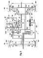
- FIG. 1 shows the essential components of a pneumatic brake system 1 of a commercial vehicle with a front axle VA with dashed lines drawn front axle wheels VA1, VA2 and a driven rear axle HA with dashed lines a left rear axle HA1 and a right rear axle HA2.
- the wheels VA1, VA2, HA1 and HA2 are braked by pneumatic brakes, of which in FIG. 1 the pneumatic brake cylinders 2, 3, 4, 5 are shown.
- speed sensors 6, 7, 8, 9 on the four wheels VA1, VA2, HA1, HA2 for measuring the rotational speeds for various control systems, in particular the ABS control, provided in accordance with measurement signals to an electronic control device 10 of the compressed air -Bremsstrom 1 spend.
- ABS solenoid valves 11, 12, 13, 14 are connected in a conventional manner, which are controlled by the control device 10.
- the compressed-air brake system 1 shown has a front-axle brake circuit 22 and a rear-axle brake circuit 20, which are controlled separately by the control device 10.
- the driver is about a here indicated only brake pedal 15 a braking request to a brake valve 16, which is also referred to as a motor vehicle brake valve and five ports 16-11, 16-12, 16-21, 16-22 and 16-4 and a Vent 16-3 has.
- the ports 16-11 and 16-21 are provided for the rear axle brake circuit 20, which is fed by a first compressed air reservoir 21.
- the connections 16-12 and 16-22 are provided for the front-axle brake circuit 22, which is supplied in accordance with a second compressed air reservoir 23.
- the compressed air reservoirs 21 and 23 are filled in a manner known per se and not shown here in detail by a compressor driven by the vehicle engine.
- the port 16-11 is connected as a compressed air inlet to the brake valve 16 to the first compressed air reservoir 21; Accordingly, the second compressed air inlet 16-12 of the second brake circuit 22 is connected to the second compressed air reservoir 23, wherein accordingly The operation of the brake pedal 15 compressed air to the respective compressed air outlets 16-21 and 16-22 and thus the connected brake pressure line 27 of the rear axle brake circuit 20 and the connected brake pressure line 58 of the front-axle brake circuit 22 is passed.
- the driver's braking request is additionally detected via a pressure sensor 24, which is connected to the brake pressure line 27 and outputs a measurement signal to the control device 10.
- a two-way valve 26 (shuttle valve) connected to its first input 26-11, the further input 26-12 via a line 28, a differential valve 30 and a check valve 31 in turn to the first compressed air reservoir 21st connected.
- the differential valve 30 is in this case designed as a 3/2-way solenoid valve, which is controlled by the control device 10.
- the differential valve 30 also has a venting connection, not shown here and known as such, in order to discharge the compressed air from the line 28 after completion of the ASR control.
- the control input of the relay valve 32 is connected, which in turn is connected to the first compressed air reservoir 21 and this connects directly to the ABS solenoid valves 13 and 14 of the rear axle HA.
- the relay valve 32 thus acts in a manner known per se to increase the throughput and to form short line paths between the first compressed air reservoir 21 and the ABS solenoid valves 13 and 14th
- the control device 10 performs in a conventional manner at the four wheels ABS control functions by when they actuate the corresponding brake cylinders 2, 3, 4, 5 via the wheel speed sensors 6, 7, 8, 9 a slip of the wheel in question or the Wheels of an axle recognizes. Furthermore, the control device 10 performs an EBL (Electronic Brake Limiter, electronic braking force limitation) - regulating function.
- the EBL control function is performed via the ABS solenoid valves 11, 12, 13, 14.
- the EBL here represents a load-dependent braking force limitation, which is particularly relevant to the rear axle, since there the different loads lead to greater differences in the axle loads and thus the blocking tendency.
- the control device 10 detects that the brake pressure or air pressure in the brake pressure supply line 33 to the ABS solenoid valves 13, 14 is large enough and the driver via the brake valve 16 desires a further increase in brake, as the pressure at the output 16-21 on is increased, the control device 10 controls the ABS solenoid valves 13, 14 such that their inputs 14-1 and 13-1 are closed and their leading to the brake cylinders 4 and 5 terminals 13-2 and 14-2 remain closed, so that the standing in the brake lines 34, 35 to the brake cylinders 4 and 5 brake pressure is locked.
- the ports 13-2 and 14-2 are thus not connected to the compressed air outlet for venting, as is done in an ABS control to release the brakes on detection of a blockage. Rather, the brake pressure is held at the value already set, so that blocking does not even occur.
- a pneumatic return control line 36 is connected to the brake line 34 and / or the brake line 35.
- the return control line 36 is connected only to the left brake line 34 and leads to the control port or control input 16-4 of the brake valve 16.
- About the control input 16-4 is in this case in the brake valve 16 of the piston, the controls the compressed air output via the output 16-22, pressurized with compressed air, so that a feedback of the brake pressure to the brake valve 16 is such that the front axle VA is mitgeregelt.
- Such activations of the brake valve 16 via a control input 16-4 are already known in principle from ALB regulations.
- an additional circuit is provided in the return control line 36, wherein in FIG. 1 Initially, a check valve 38 is connected between the partial lines 36-1 and 36-2 such that a return of compressed air from the port 16-4 to the line 34 is excluded. Furthermore, another check valve 39 between the port 16-4 and z. B. the connection 16-21 provided such that a venting of the present at the port 16-4 brake pressure via the port 16-21 and the vent 16-3 of the brake valve 16 is made possible.
- the effect of the feedback control line 36 is based on FIG. 1 explained. If the control device 10 recognizes that a sufficient brake pressure already exists in the brake lines 34, 35 and thus in the brake cylinders 4, 5 of the rear axle HA and a further increase in brake pressure could possibly lead to a tendency for the rear brakes to lock, which is especially the case with a lower load the rear axle HA can also be done with smaller brake pressures, and the driver via the brake valve 16, a higher brake pressure or stronger braking is desired, then recognizes the controller 10, that the brake pressure in the lines 34, 35 should not be increased and controls in the Under the EBL control the ABS valves 13, 14 such that their input and output is closed and thus the brake pressure in the brake lines 34, 35 is held or locked.
- this brake pressure is input to the port 16-4 of the brake valve 16 so that via this feedback the braking behavior on the front axle VA in dependence on the axle load of the rear axle HA can be mitgeregelt.
- the check valve 38 prevents in this case that in the ABS control case of the ABS solenoid valve 13 in an undesired manner, this ABS control via the control input 16-4 to control the front axle VA influence.
- the ABS control is closed on the ABS solenoid valve 13 upon detection of an incipient lock of the left rear wheel HA1 the input 13-1 of the ABS solenoid valve 13 and further - unlike the above-described EBL control - the exhaust valve or vent valve of the ABS - Solenoid valves open, so that the pending in the brake pressure line 34 brake pressure on the ABS solenoid valve 13 can escape to the outside and the rear wheel HA1 subsequently detected again by the road and can be rotated.
- FIG. 1 only the pressure of the left brake pipe 34 of the rear axle HA is used for the control return.
- a double check valve (shuttle valve) 40 is provided between the brake lines 34 and 35, the third port of which is connected to the return control line 36, which in turn is connected to the port 16-4 via the check valve 39 as in FIG. 1 can be vented.
- the double check valve 40 closes to this brake line.
- the double check valve 40 has, as shown in the symbolic representation of Fig. 2 it can be seen, advantageously two sealing elements, so that it locks even at a pressure drop at both brake lines.
- the higher brake pressure of the line 34 and 35 via the return control line 36 returned.
- the higher brake pressure exerted before the occurrence of the ABS event remains in the return control line 36
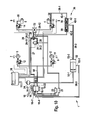
- FIG. 3 shows a further embodiment in which - purely for clarity - only from the left brake pressure line 34 is returned.
- FIG. 1 and FIG. 3 can z. B. also on the right brake line 35, continue to Fig. 3 With Fig. 2 be combined.
- a combination valve 42 is connected, which contains the two check valves 38 and 39.
- the functionality of the check valves 38 and 39 in the combination valve 42 thus corresponds to the functionality of the check valves 38 and 39 in FIG FIG. 1 , Accordingly, the control port 16-4 is controlled via the central port 42-3 of the combination valve 42.
- Fig. 3 the bleed-off check valve 39 is connected to the line 29 which extends from the two-way valve 26 to the relay valve 32. A venting via the check valve 39 and the two-way valve (shuttle valve) 26. Basically, other connections of the non-return valve 39 serving for venting are possible here.
- FIGS. 4a and 4b show possible embodiments of the combination valve 42, wherein in the housing 42a corresponding bores, check valve body 38a and 39a and corresponding check valve springs 38b and 39b are added.
- the check valve body 38a, 39a are formed as a rubber body
- FIG. 4b correspondingly as valve balls which are pressed against the corresponding valve seats in the valve housing 42a.
- the combination valve 42 can thus in principle as a double check valve (shuttle valve), in which the check valve 39 is arranged reversely or inversely, or represented as a double check valve with inverse check valve 38 and also formed. The production is thus by corresponding reverse installation of each check valve very simple and inexpensive.
- the check valves 38 and 39 are according to FIG. 1 plotted, wherein in the return control line 36 in addition a 2/2-way valve 44 between the control port 16-4 and the output of the check valve 38 and thus to the part-line 36-2 of the FIG. 1 connected.
- the valve 44 thus acts as a check valve 44, the control input 44a is pneumatically connected via a line 45 to the line 28 and thus is driven by a port 26-12 of the two-way valve 26 and the port 30-2 of the differential valve 30.
- the check valve 44 is in passage position, so that the functionality of the FIG.
- the return to the control port 16-4 of the brake valve 16 is carried out to allow co-regulation of the front axle in dependence on the axle load of the rear axle HA.
- the brake pressure line 27 is vented through the outlet 16-21 so that the input 26-11 of the two-way valve 26 turns on and closes the port 26-12, so that the relay valve 32 is driven and switched through the brake pressure line 27.
- the line 28 is depressurized to the in FIG. 5 is connected via the compressed air line 45, the terminal 44a.
- the check valve 44 remains in the forward passage position shown, so that the functionality of the figure that of FIG. 1 and 3 equivalent.
- FIG. 5 additionally takes into account the ASR rule case in which it is detected on the rotational speed sensor 8 that the left wheel of the rear axle HA and thus the driven rear axle HA slip or drive slip tends and is thus braked in a conventional manner via the ABS solenoid valve 13.
- the ABS solenoid valve 13 corresponding to the ABS solenoid valve 14 on the right side in the case of an ASR control case
- the brake valve 16 is operated without the brake valve 16 being actuated, so that the brake pressure line 27 is not acted upon by brake pressure.
- the two-way valve (shuttle valve) 26 is controlled via its port 26-12, so that the line 45 is vented and the 2/2-way valve 44 opens in the blocking position, so that the return line between the line areas 36-2 and 36-3 is disabled, so that in the ASR rule no tax return occurs.
- the combination valve 42 is provided, which is connected according to the illustration shown here, however, to the brake line 34 and for venting to the connection of the two-way valve 26 which is connected to the relay valve 32, so that a vent via the two-way valve 26 is possible.
- FIG. 7 shows the formation of the valves 42 and 44 FIG. 6 in an exemplary representation.
- FIG. 8 In the embodiment of the FIG. 8 is connected between the check valve 38 and the control port 16-4 a 3/2 way valve 50 that is pneumatically controlled by the output 16-21 of the brake valve 16.
- the return control line 36 In the rest position shown, the return control line 36 is blocked by the 3/2-way valve 50 or check valve.
- the brake pressure line 27 In a braking operation of the driver, the brake pressure line 27 is vented via the output 16-21 of the brake valve 16 and thus the 3/2-way valve 50 is moved to its open position, so that as above with respect to FIG. 1 . 3 described the EBL control can be done and the check valve 38 locks in ABS rule case.
- the vent serving check valve 39 is connected to the line 29.
- a Doppelabsperrventil 52 is connected with its inputs 52-1 and 52-2 between the return control line 36-2 and the brake pressure line 27 and the output 16-21 of the brake valve 16.
- the output 52-3 of the double shut-off valve is correspondingly connected via the line 36-3 to the control connection 16-4 of the brake valve 16.
- the line 36-2 or 27 is placed on the line 36-3 at the lower pressure, respectively.
- the pending in the brake pressure line 27 air pressure will be higher than that of the relay valve 32 via the switched ABS solenoid valve 13 and the check valve 38 to the line 36-2 set pressure; Even at approximately the same pressure, this brake pressure is thus applied to the line 36-3 and thus to the control connection 16-4, so that the desired feedback for co-regulation of the front axle takes place.
- the check valve 38 when the ABS solenoid valve 13, the brake line 34 and thus the area 36-1 of the return control line 36 vented.
- FIG. 10 shows one of the FIG. 9 corresponding embodiment in which the check valves 38 and 39 in turn in a combination valve 42 according to the embodiments described above, for. B. FIG. 3 , are recorded.
- FIG. 11 shows a corresponding embodiment with sectional views of these valves 42 and 52nd
- FIG. 12 shows a further embodiment in which a valve device 54 according to the invention forms the additional circuit in the return control line 36.
- the valve device 54 in this case has the check valves 38 and 39 according to the embodiments described above, the z. B. accordingly FIG. 9 are connected, ie between the brake pipe 34 and the compressed air line 29 and in the arrangement described therein; the valve device 54 is thus connected with its connections 54-2 to the lines 29 and 54-1 to the brake line 34.
- the valve device 54 has a control input 54-3, which is connected to the line 28 between the differential valve 30 and the two-way valve 26, that is, at the terminal 26-12.
- the output 54-4 of the valve device 54 according to the invention is connected to the control port 16-4 of the brake valve 16.
- the valve device 54 in this case has a housing 54 a with an in FIG. 12 horizontal bore 54b, in which the check valves 38 and 39 - are used - according to the combination valve 42 described above - further, a in FIG. 12 vertically drawn second bore 54c, in which a control piston 55 are included together with the return spring 56, the holes 54b and 54c intersect in this case and thus merge into one another.
- the bore 54b has outwardly each two spacers as chambers, in which the check valves 38, 39 with the valve bodies 38a, 39a and valve springs 38b, 39b are inserted, which are closed to the outside by cover 54d and 54e and with seals, for. B. O-rings are sealed. Accordingly, the vertical chamber 54c is widened upward and closed with a lid 54f and with a seal, for. B. O-ring sealed.
- the control piston 55 serves, upon actuation, ie at input pressure at the control input 54-3, to reach against a housing-side valve seat 57, wherein it is displaced by the return spring 56 back to the open position at pressure drop at the control input.
- other connections of the control input 54-3, ie to other lines than the line 28 are possible; it is relevant that the function according to the invention is fulfilled.
- the line 28 from the differential valve 30 to the two-way valve 26 is only vented if, in the absence of actuation of the brake valve 16 yet braking to the rear axle is desired, ie in the ASR rule.
- the valve device 54 according to the invention thus makes it possible to integrate or combine the additional circuit used in the feedback control line 36 according to the invention.
- the valves 38, 39 on the one hand and the output 54-4 on the other hand be kept low on the other hand
- the valve device 54 according to the invention can thus in a vehicle, for. B. in an existing brake system, to the lines shown 28, 29, 34 and a port 16-4 are connected and ensures full functionality with low volumes between the valves and reduced risk of z. B. Damage to the pipes between the valves.
- control inputs of the valves of the additional circuit can be controlled differently.
- This z. In Fig. 5 to 7 and Fig. 12 in the valves 44 and 54, the unconfirmed basic position and set when pressurizing their control inputs 44a and 54-3 operating position are reversed by these control inputs are connected to the brake pressure line 27 and thus pressurized upon actuation of the brake valve 16 and turn on and in the ASR Case remain in the rest position.
Landscapes
- Engineering & Computer Science (AREA)
- Transportation (AREA)
- Mechanical Engineering (AREA)
- Physics & Mathematics (AREA)
- Fluid Mechanics (AREA)
- Electromagnetism (AREA)
- Regulating Braking Force (AREA)
- Hydraulic Control Valves For Brake Systems (AREA)
- Braking Systems And Boosters (AREA)
Applications Claiming Priority (1)
| Application Number | Priority Date | Filing Date | Title |
|---|---|---|---|
| DE200910022164 DE102009022164A1 (de) | 2009-05-20 | 2009-05-20 | Bremsanlage für ein Fahrzeug, Verfahren zum Betreiben der Bremsanlage und Ventileinrichtung für eine Bremsanlage |
Publications (3)
| Publication Number | Publication Date |
|---|---|
| EP2256011A2 true EP2256011A2 (fr) | 2010-12-01 |
| EP2256011A3 EP2256011A3 (fr) | 2013-11-13 |
| EP2256011B1 EP2256011B1 (fr) | 2015-07-29 |
Family
ID=42357456
Family Applications (1)
| Application Number | Title | Priority Date | Filing Date |
|---|---|---|---|
| EP10000564.4A Active EP2256011B1 (fr) | 2009-05-20 | 2010-01-21 | Système de freinage pour véhicule et procédé pour faire fonctionner ce système de freinage |
Country Status (2)
| Country | Link |
|---|---|
| EP (1) | EP2256011B1 (fr) |
| DE (1) | DE102009022164A1 (fr) |
Cited By (5)
| Publication number | Priority date | Publication date | Assignee | Title |
|---|---|---|---|---|
| WO2017076483A1 (fr) * | 2015-11-04 | 2017-05-11 | Wabco Gmbh | Système de freinage hydraulique |
| FR3052723A1 (fr) * | 2016-06-16 | 2017-12-22 | Poclain Hydraulics Ind | Systeme de freinage mecaniquement maintenu |
| CN110936943A (zh) * | 2019-11-13 | 2020-03-31 | 广州瑞立科密汽车电子股份有限公司 | 一种商用车电控制动系统 |
| WO2020120738A1 (fr) * | 2018-12-14 | 2020-06-18 | Cnh Industrial Italia S.P.A. | Agencement de freinage hydraulique pour véhicules tout-terrain |
| CN113874264A (zh) * | 2019-05-28 | 2021-12-31 | 采埃孚商用车系统汉诺威有限公司 | 具有两个单通道车桥调制器和abs阀的电子控制的气动制动系统以及具有这种制动系统的车辆 |
Families Citing this family (2)
| Publication number | Priority date | Publication date | Assignee | Title |
|---|---|---|---|---|
| CN105151029A (zh) * | 2015-08-21 | 2015-12-16 | 湖北航天技术研究院特种车辆技术中心 | 一种无人驾驶重型车的制动系统及方法 |
| DE102022122503A1 (de) | 2022-09-06 | 2024-03-07 | Zf Cv Systems Europe Bv | Rückschlagventil für eine Drucklufteinrichtung eines Fahrzeugs |
Family Cites Families (3)
| Publication number | Priority date | Publication date | Assignee | Title |
|---|---|---|---|---|
| DE19640141A1 (de) * | 1996-09-28 | 1998-04-02 | Bosch Gmbh Robert | Schlupfgeregelte Druckluft-Bremsanlage für Nutzfahrzeuge |
| DE19947753A1 (de) * | 1999-10-02 | 2001-04-19 | Daimler Chrysler Ag | Druckluftbetätigte Bremseinrichtung |
| DE10350560A1 (de) * | 2003-10-29 | 2005-06-02 | Daimlerchrysler Ag | Bremsanlage, insbesondere für Nutzfahrzeuge |
-
2009
- 2009-05-20 DE DE200910022164 patent/DE102009022164A1/de not_active Withdrawn
-
2010
- 2010-01-21 EP EP10000564.4A patent/EP2256011B1/fr active Active
Non-Patent Citations (1)
| Title |
|---|
| None |
Cited By (9)
| Publication number | Priority date | Publication date | Assignee | Title |
|---|---|---|---|---|
| WO2017076483A1 (fr) * | 2015-11-04 | 2017-05-11 | Wabco Gmbh | Système de freinage hydraulique |
| US10543819B2 (en) | 2015-11-04 | 2020-01-28 | Wabco Gmbh | Hydraulic braking system |
| FR3052723A1 (fr) * | 2016-06-16 | 2017-12-22 | Poclain Hydraulics Ind | Systeme de freinage mecaniquement maintenu |
| WO2020120738A1 (fr) * | 2018-12-14 | 2020-06-18 | Cnh Industrial Italia S.P.A. | Agencement de freinage hydraulique pour véhicules tout-terrain |
| CN113165624A (zh) * | 2018-12-14 | 2021-07-23 | 凯斯纽荷兰(中国)管理有限公司 | 用于非道路车辆的液压制动装置 |
| CN113165624B (zh) * | 2018-12-14 | 2024-02-02 | 凯斯纽荷兰工业(哈尔滨)机械有限公司 | 用于非道路车辆的液压制动装置 |
| CN113874264A (zh) * | 2019-05-28 | 2021-12-31 | 采埃孚商用车系统汉诺威有限公司 | 具有两个单通道车桥调制器和abs阀的电子控制的气动制动系统以及具有这种制动系统的车辆 |
| CN113874264B (zh) * | 2019-05-28 | 2024-06-07 | 采埃孚商用车系统欧洲有限公司 | 具有两个单通道车桥调制器和abs阀的电子控制的气动制动系统以及具有这种制动系统的车辆 |
| CN110936943A (zh) * | 2019-11-13 | 2020-03-31 | 广州瑞立科密汽车电子股份有限公司 | 一种商用车电控制动系统 |
Also Published As
| Publication number | Publication date |
|---|---|
| EP2256011B1 (fr) | 2015-07-29 |
| EP2256011A3 (fr) | 2013-11-13 |
| DE102009022164A1 (de) | 2010-11-25 |
Similar Documents
| Publication | Publication Date | Title |
|---|---|---|
| EP3600991B1 (fr) | Frein à main électro-pneumatique avec tcv integré (commande scandinave) | |
| EP3600996B1 (fr) | Module integre pour remorque avec unité externe de freinage de stationnement electro-pneumatique | |
| DE102010010606B4 (de) | Modular aufgebaute Drucksteuervorrichtung einer Druckmittel-Bremsanlage eines Fahrzeugs | |
| EP2190706B1 (fr) | Ensemble de vanne destiné à commander l'installation de freinage d'un véhicule tracté | |
| EP2256011B1 (fr) | Système de freinage pour véhicule et procédé pour faire fonctionner ce système de freinage | |
| EP3600981A1 (fr) | Frein à main électro-pneumatique (eph) avec valve tcv (système de commande européen et scandinave) intégrée | |
| EP3368387B1 (fr) | Control de frein de verrouillage électropneumatique avec control pneumatique redondant | |
| EP3678909A1 (fr) | Dispositif de commande de frein de stationnement électropneumatique et système de freinage d'un véhicule | |
| EP2238004A2 (fr) | Frein de stationnement | |
| EP3356192A1 (fr) | Dispositif de frein de stationnement électro-pneumatique d'un véhicule comprenant un autre circuit de commande | |
| EP3129264A1 (fr) | Dispositif de commande électropneumatique de frein de stationnement | |
| EP3694755A1 (fr) | Module de freinage de stationnement électropneumatique pour véhicules utilitaires comprenant des freins de stationnement à ressort accumulateur | |
| EP1188634A2 (fr) | Soupape de frein de remorque pour remorques à commande de freinage électronique et à sécurité améliorée de remorque stationnée | |
| DE102012107203B4 (de) | Pneumatische Bremseinrichtung eines Fahrzeugs mit vom Parkbremsventil zwangsgesteuerter Interlock-Einrichtung | |
| DE19918070B4 (de) | Druckregelvorrichtung für elektro-pneumatische Bremsanlagen von Fahrzeugen, insbesondere Nutzfahrzeugen | |
| EP3626564A1 (fr) | Soupape de commande, système de freinage à commande électronique ainsi que procédé de commande du système de freinage à commande électronique | |
| EP3010772A1 (fr) | Dispositif de commande permettant de commander les freins d'une combinaison entre un véhicule tracteur et une remorque | |
| EP3390178B1 (fr) | Systeme pour commander un système de frein de stationnement électropneumatique d'un véhicule pendant la conduite en tant que frein de secours | |
| EP3507148A1 (fr) | Système de freinage pneumatique pour un véhicule tracté | |
| EP2285634A1 (fr) | Système de freinage hydraulique | |
| DE19933483C1 (de) | Druckmittelbetätigte Fahrzeugbremsanlage | |
| DE3605220A1 (de) | Schlupfgeregelte bremsanlage | |
| DE102018002488B4 (de) | Bremssystem eines Fahrzeugzuges | |
| DE10042215C5 (de) | Druckmittelbetätigte Fahrzeugbremsanlage mit redundanter Ansteuerung wenigstens eines Bremszylinders | |
| DE20122549U1 (de) | Anhängerbremsventil für Anhängefahrzeuge mit elektronischer Bremsregelung und erweiterter Sicherheit des geparkten Anhängers |
Legal Events
| Date | Code | Title | Description |
|---|---|---|---|
| PUAI | Public reference made under article 153(3) epc to a published international application that has entered the european phase |
Free format text: ORIGINAL CODE: 0009012 |
|
| AK | Designated contracting states |
Kind code of ref document: A2 Designated state(s): AT BE BG CH CY CZ DE DK EE ES FI FR GB GR HR HU IE IS IT LI LT LU LV MC MK MT NL NO PL PT RO SE SI SK SM TR |
|
| AX | Request for extension of the european patent |
Extension state: AL BA RS |
|
| PUAL | Search report despatched |
Free format text: ORIGINAL CODE: 0009013 |
|
| AK | Designated contracting states |
Kind code of ref document: A3 Designated state(s): AT BE BG CH CY CZ DE DK EE ES FI FR GB GR HR HU IE IS IT LI LT LU LV MC MK MT NL NO PL PT RO SE SI SK SM TR |
|
| AX | Request for extension of the european patent |
Extension state: AL BA RS |
|
| RIC1 | Information provided on ipc code assigned before grant |
Ipc: B60T 13/68 20060101ALN20131007BHEP Ipc: B60T 8/36 20060101AFI20131007BHEP Ipc: B60T 8/30 20060101ALI20131007BHEP Ipc: B60T 8/26 20060101ALI20131007BHEP |
|
| 17P | Request for examination filed |
Effective date: 20140513 |
|
| RBV | Designated contracting states (corrected) |
Designated state(s): AT BE BG CH CY CZ DE DK EE ES FI FR GB GR HR HU IE IS IT LI LT LU LV MC MK MT NL NO PL PT RO SE SI SK SM TR |
|
| 17Q | First examination report despatched |
Effective date: 20140605 |
|
| RIC1 | Information provided on ipc code assigned before grant |
Ipc: B60T 13/68 20060101ALN20150304BHEP Ipc: B60T 8/30 20060101ALI20150304BHEP Ipc: B60T 8/36 20060101AFI20150304BHEP Ipc: B60T 8/26 20060101ALI20150304BHEP |
|
| GRAP | Despatch of communication of intention to grant a patent |
Free format text: ORIGINAL CODE: EPIDOSNIGR1 |
|
| INTG | Intention to grant announced |
Effective date: 20150410 |
|
| GRAS | Grant fee paid |
Free format text: ORIGINAL CODE: EPIDOSNIGR3 |
|
| GRAA | (expected) grant |
Free format text: ORIGINAL CODE: 0009210 |
|
| AK | Designated contracting states |
Kind code of ref document: B1 Designated state(s): AT BE BG CH CY CZ DE DK EE ES FI FR GB GR HR HU IE IS IT LI LT LU LV MC MK MT NL NO PL PT RO SE SI SK SM TR |
|
| REG | Reference to a national code |
Ref country code: GB Ref legal event code: FG4D Free format text: NOT ENGLISH |
|
| REG | Reference to a national code |
Ref country code: CH Ref legal event code: EP |
|
| REG | Reference to a national code |
Ref country code: AT Ref legal event code: REF Ref document number: 739005 Country of ref document: AT Kind code of ref document: T Effective date: 20150815 |
|
| REG | Reference to a national code |
Ref country code: IE Ref legal event code: FG4D Free format text: LANGUAGE OF EP DOCUMENT: GERMAN |
|
| REG | Reference to a national code |
Ref country code: DE Ref legal event code: R096 Ref document number: 502010009908 Country of ref document: DE |
|
| REG | Reference to a national code |
Ref country code: SE Ref legal event code: TRGR |
|
| REG | Reference to a national code |
Ref country code: LT Ref legal event code: MG4D |
|
| REG | Reference to a national code |
Ref country code: NL Ref legal event code: FP |
|
| PG25 | Lapsed in a contracting state [announced via postgrant information from national office to epo] |
Ref country code: FI Free format text: LAPSE BECAUSE OF FAILURE TO SUBMIT A TRANSLATION OF THE DESCRIPTION OR TO PAY THE FEE WITHIN THE PRESCRIBED TIME-LIMIT Effective date: 20150729 Ref country code: LT Free format text: LAPSE BECAUSE OF FAILURE TO SUBMIT A TRANSLATION OF THE DESCRIPTION OR TO PAY THE FEE WITHIN THE PRESCRIBED TIME-LIMIT Effective date: 20150729 Ref country code: NO Free format text: LAPSE BECAUSE OF FAILURE TO SUBMIT A TRANSLATION OF THE DESCRIPTION OR TO PAY THE FEE WITHIN THE PRESCRIBED TIME-LIMIT Effective date: 20151029 Ref country code: LV Free format text: LAPSE BECAUSE OF FAILURE TO SUBMIT A TRANSLATION OF THE DESCRIPTION OR TO PAY THE FEE WITHIN THE PRESCRIBED TIME-LIMIT Effective date: 20150729 Ref country code: GR Free format text: LAPSE BECAUSE OF FAILURE TO SUBMIT A TRANSLATION OF THE DESCRIPTION OR TO PAY THE FEE WITHIN THE PRESCRIBED TIME-LIMIT Effective date: 20151030 |
|
| PG25 | Lapsed in a contracting state [announced via postgrant information from national office to epo] |
Ref country code: IS Free format text: LAPSE BECAUSE OF FAILURE TO SUBMIT A TRANSLATION OF THE DESCRIPTION OR TO PAY THE FEE WITHIN THE PRESCRIBED TIME-LIMIT Effective date: 20151129 Ref country code: PL Free format text: LAPSE BECAUSE OF FAILURE TO SUBMIT A TRANSLATION OF THE DESCRIPTION OR TO PAY THE FEE WITHIN THE PRESCRIBED TIME-LIMIT Effective date: 20150729 Ref country code: ES Free format text: LAPSE BECAUSE OF FAILURE TO SUBMIT A TRANSLATION OF THE DESCRIPTION OR TO PAY THE FEE WITHIN THE PRESCRIBED TIME-LIMIT Effective date: 20150729 Ref country code: HR Free format text: LAPSE BECAUSE OF FAILURE TO SUBMIT A TRANSLATION OF THE DESCRIPTION OR TO PAY THE FEE WITHIN THE PRESCRIBED TIME-LIMIT Effective date: 20150729 Ref country code: PT Free format text: LAPSE BECAUSE OF FAILURE TO SUBMIT A TRANSLATION OF THE DESCRIPTION OR TO PAY THE FEE WITHIN THE PRESCRIBED TIME-LIMIT Effective date: 20151130 |
|
| PG25 | Lapsed in a contracting state [announced via postgrant information from national office to epo] |
Ref country code: EE Free format text: LAPSE BECAUSE OF FAILURE TO SUBMIT A TRANSLATION OF THE DESCRIPTION OR TO PAY THE FEE WITHIN THE PRESCRIBED TIME-LIMIT Effective date: 20150729 Ref country code: DK Free format text: LAPSE BECAUSE OF FAILURE TO SUBMIT A TRANSLATION OF THE DESCRIPTION OR TO PAY THE FEE WITHIN THE PRESCRIBED TIME-LIMIT Effective date: 20150729 Ref country code: SK Free format text: LAPSE BECAUSE OF FAILURE TO SUBMIT A TRANSLATION OF THE DESCRIPTION OR TO PAY THE FEE WITHIN THE PRESCRIBED TIME-LIMIT Effective date: 20150729 Ref country code: CZ Free format text: LAPSE BECAUSE OF FAILURE TO SUBMIT A TRANSLATION OF THE DESCRIPTION OR TO PAY THE FEE WITHIN THE PRESCRIBED TIME-LIMIT Effective date: 20150729 |
|
| REG | Reference to a national code |
Ref country code: DE Ref legal event code: R097 Ref document number: 502010009908 Country of ref document: DE |
|
| PG25 | Lapsed in a contracting state [announced via postgrant information from national office to epo] |
Ref country code: BE Free format text: LAPSE BECAUSE OF NON-PAYMENT OF DUE FEES Effective date: 20160131 Ref country code: RO Free format text: LAPSE BECAUSE OF FAILURE TO SUBMIT A TRANSLATION OF THE DESCRIPTION OR TO PAY THE FEE WITHIN THE PRESCRIBED TIME-LIMIT Effective date: 20150729 |
|
| PLBE | No opposition filed within time limit |
Free format text: ORIGINAL CODE: 0009261 |
|
| STAA | Information on the status of an ep patent application or granted ep patent |
Free format text: STATUS: NO OPPOSITION FILED WITHIN TIME LIMIT |
|
| 26N | No opposition filed |
Effective date: 20160502 |
|
| PG25 | Lapsed in a contracting state [announced via postgrant information from national office to epo] |
Ref country code: SI Free format text: LAPSE BECAUSE OF FAILURE TO SUBMIT A TRANSLATION OF THE DESCRIPTION OR TO PAY THE FEE WITHIN THE PRESCRIBED TIME-LIMIT Effective date: 20150729 Ref country code: LU Free format text: LAPSE BECAUSE OF FAILURE TO SUBMIT A TRANSLATION OF THE DESCRIPTION OR TO PAY THE FEE WITHIN THE PRESCRIBED TIME-LIMIT Effective date: 20160121 |
|
| REG | Reference to a national code |
Ref country code: CH Ref legal event code: PL |
|
| GBPC | Gb: european patent ceased through non-payment of renewal fee |
Effective date: 20160121 |
|
| PG25 | Lapsed in a contracting state [announced via postgrant information from national office to epo] |
Ref country code: MC Free format text: LAPSE BECAUSE OF FAILURE TO SUBMIT A TRANSLATION OF THE DESCRIPTION OR TO PAY THE FEE WITHIN THE PRESCRIBED TIME-LIMIT Effective date: 20150729 |
|
| REG | Reference to a national code |
Ref country code: FR Ref legal event code: ST Effective date: 20160930 |
|
| PG25 | Lapsed in a contracting state [announced via postgrant information from national office to epo] |
Ref country code: LI Free format text: LAPSE BECAUSE OF NON-PAYMENT OF DUE FEES Effective date: 20160131 Ref country code: CH Free format text: LAPSE BECAUSE OF NON-PAYMENT OF DUE FEES Effective date: 20160131 Ref country code: GB Free format text: LAPSE BECAUSE OF NON-PAYMENT OF DUE FEES Effective date: 20160121 |
|
| REG | Reference to a national code |
Ref country code: IE Ref legal event code: MM4A |
|
| PG25 | Lapsed in a contracting state [announced via postgrant information from national office to epo] |
Ref country code: FR Free format text: LAPSE BECAUSE OF NON-PAYMENT OF DUE FEES Effective date: 20160201 |
|
| PG25 | Lapsed in a contracting state [announced via postgrant information from national office to epo] |
Ref country code: IE Free format text: LAPSE BECAUSE OF NON-PAYMENT OF DUE FEES Effective date: 20160121 |
|
| REG | Reference to a national code |
Ref country code: AT Ref legal event code: MM01 Ref document number: 739005 Country of ref document: AT Kind code of ref document: T Effective date: 20160121 |
|
| PG25 | Lapsed in a contracting state [announced via postgrant information from national office to epo] |
Ref country code: AT Free format text: LAPSE BECAUSE OF NON-PAYMENT OF DUE FEES Effective date: 20160121 |
|
| PG25 | Lapsed in a contracting state [announced via postgrant information from national office to epo] |
Ref country code: MT Free format text: LAPSE BECAUSE OF FAILURE TO SUBMIT A TRANSLATION OF THE DESCRIPTION OR TO PAY THE FEE WITHIN THE PRESCRIBED TIME-LIMIT Effective date: 20150729 |
|
| REG | Reference to a national code |
Ref country code: DE Ref legal event code: R081 Ref document number: 502010009908 Country of ref document: DE Owner name: WABCO EUROPE BVBA, BE Free format text: FORMER OWNER: WABCO GMBH, 30453 HANNOVER, DE |
|
| PG25 | Lapsed in a contracting state [announced via postgrant information from national office to epo] |
Ref country code: CY Free format text: LAPSE BECAUSE OF FAILURE TO SUBMIT A TRANSLATION OF THE DESCRIPTION OR TO PAY THE FEE WITHIN THE PRESCRIBED TIME-LIMIT Effective date: 20150729 Ref country code: HU Free format text: LAPSE BECAUSE OF FAILURE TO SUBMIT A TRANSLATION OF THE DESCRIPTION OR TO PAY THE FEE WITHIN THE PRESCRIBED TIME-LIMIT; INVALID AB INITIO Effective date: 20100121 Ref country code: SM Free format text: LAPSE BECAUSE OF FAILURE TO SUBMIT A TRANSLATION OF THE DESCRIPTION OR TO PAY THE FEE WITHIN THE PRESCRIBED TIME-LIMIT Effective date: 20150729 |
|
| PG25 | Lapsed in a contracting state [announced via postgrant information from national office to epo] |
Ref country code: MK Free format text: LAPSE BECAUSE OF FAILURE TO SUBMIT A TRANSLATION OF THE DESCRIPTION OR TO PAY THE FEE WITHIN THE PRESCRIBED TIME-LIMIT Effective date: 20150729 Ref country code: TR Free format text: LAPSE BECAUSE OF FAILURE TO SUBMIT A TRANSLATION OF THE DESCRIPTION OR TO PAY THE FEE WITHIN THE PRESCRIBED TIME-LIMIT Effective date: 20150729 |
|
| PG25 | Lapsed in a contracting state [announced via postgrant information from national office to epo] |
Ref country code: BG Free format text: LAPSE BECAUSE OF FAILURE TO SUBMIT A TRANSLATION OF THE DESCRIPTION OR TO PAY THE FEE WITHIN THE PRESCRIBED TIME-LIMIT Effective date: 20150729 |
|
| REG | Reference to a national code |
Ref country code: DE Ref legal event code: R081 Ref document number: 502010009908 Country of ref document: DE Owner name: ZF CV SYSTEMS EUROPE BV, BE Free format text: FORMER OWNER: WABCO EUROPE BVBA, BRUESSEL, BE |
|
| P01 | Opt-out of the competence of the unified patent court (upc) registered |
Effective date: 20230528 |
|
| PGFP | Annual fee paid to national office [announced via postgrant information from national office to epo] |
Ref country code: SE Payment date: 20231213 Year of fee payment: 15 Ref country code: NL Payment date: 20231215 Year of fee payment: 15 |
|
| PGFP | Annual fee paid to national office [announced via postgrant information from national office to epo] |
Ref country code: IT Payment date: 20231212 Year of fee payment: 15 |
|
| PGFP | Annual fee paid to national office [announced via postgrant information from national office to epo] |
Ref country code: DE Payment date: 20241203 Year of fee payment: 16 |
|
| REG | Reference to a national code |
Ref country code: SE Ref legal event code: EUG |
|
| REG | Reference to a national code |
Ref country code: NL Ref legal event code: MM Effective date: 20250201 |
|
| PG25 | Lapsed in a contracting state [announced via postgrant information from national office to epo] |
Ref country code: NL Free format text: LAPSE BECAUSE OF NON-PAYMENT OF DUE FEES Effective date: 20250201 |
|
| PG25 | Lapsed in a contracting state [announced via postgrant information from national office to epo] |
Ref country code: IT Free format text: LAPSE BECAUSE OF NON-PAYMENT OF DUE FEES Effective date: 20250121 |