EP2256227B1 - Procédé de réparation d'un élément - Google Patents
Procédé de réparation d'un élément Download PDFInfo
- Publication number
- EP2256227B1 EP2256227B1 EP08873381.1A EP08873381A EP2256227B1 EP 2256227 B1 EP2256227 B1 EP 2256227B1 EP 08873381 A EP08873381 A EP 08873381A EP 2256227 B1 EP2256227 B1 EP 2256227B1
- Authority
- EP
- European Patent Office
- Prior art keywords
- repairing
- buildup layer
- worn
- thickness
- present
- Prior art date
- Legal status (The legal status is an assumption and is not a legal conclusion. Google has not performed a legal analysis and makes no representation as to the accuracy of the status listed.)
- Not-in-force
Links
- 238000000034 method Methods 0.000 title claims description 32
- 238000005507 spraying Methods 0.000 claims description 12
- 239000010935 stainless steel Substances 0.000 claims description 12
- 229910001220 stainless steel Inorganic materials 0.000 claims description 12
- 229910001018 Cast iron Inorganic materials 0.000 claims description 9
- 239000007769 metal material Substances 0.000 claims description 5
- 229910003310 Ni-Al Inorganic materials 0.000 claims description 4
- 229910045601 alloy Inorganic materials 0.000 claims description 4
- 239000000956 alloy Substances 0.000 claims description 4
- 238000007751 thermal spraying Methods 0.000 claims description 2
- 239000000463 material Substances 0.000 description 13
- 238000010586 diagram Methods 0.000 description 5
- 230000000694 effects Effects 0.000 description 5
- 238000002485 combustion reaction Methods 0.000 description 4
- 229910000975 Carbon steel Inorganic materials 0.000 description 2
- 229910000831 Steel Inorganic materials 0.000 description 2
- 239000010962 carbon steel Substances 0.000 description 2
- 239000010959 steel Substances 0.000 description 2
- 238000010998 test method Methods 0.000 description 2
- 239000002699 waste material Substances 0.000 description 2
- 230000007423 decrease Effects 0.000 description 1
- 230000001747 exhibiting effect Effects 0.000 description 1
- 238000005259 measurement Methods 0.000 description 1
- 239000002184 metal Substances 0.000 description 1
- 229910052751 metal Inorganic materials 0.000 description 1
- 238000013001 point bending Methods 0.000 description 1
- 238000002360 preparation method Methods 0.000 description 1
Images


Classifications
-
- C—CHEMISTRY; METALLURGY
- C23—COATING METALLIC MATERIAL; COATING MATERIAL WITH METALLIC MATERIAL; CHEMICAL SURFACE TREATMENT; DIFFUSION TREATMENT OF METALLIC MATERIAL; COATING BY VACUUM EVAPORATION, BY SPUTTERING, BY ION IMPLANTATION OR BY CHEMICAL VAPOUR DEPOSITION, IN GENERAL; INHIBITING CORROSION OF METALLIC MATERIAL OR INCRUSTATION IN GENERAL
- C23C—COATING METALLIC MATERIAL; COATING MATERIAL WITH METALLIC MATERIAL; SURFACE TREATMENT OF METALLIC MATERIAL BY DIFFUSION INTO THE SURFACE, BY CHEMICAL CONVERSION OR SUBSTITUTION; COATING BY VACUUM EVAPORATION, BY SPUTTERING, BY ION IMPLANTATION OR BY CHEMICAL VAPOUR DEPOSITION, IN GENERAL
- C23C4/00—Coating by spraying the coating material in the molten state, e.g. by flame, plasma or electric discharge
- C23C4/02—Pretreatment of the material to be coated, e.g. for coating on selected surface areas
-
- C—CHEMISTRY; METALLURGY
- C23—COATING METALLIC MATERIAL; COATING MATERIAL WITH METALLIC MATERIAL; CHEMICAL SURFACE TREATMENT; DIFFUSION TREATMENT OF METALLIC MATERIAL; COATING BY VACUUM EVAPORATION, BY SPUTTERING, BY ION IMPLANTATION OR BY CHEMICAL VAPOUR DEPOSITION, IN GENERAL; INHIBITING CORROSION OF METALLIC MATERIAL OR INCRUSTATION IN GENERAL
- C23C—COATING METALLIC MATERIAL; COATING MATERIAL WITH METALLIC MATERIAL; SURFACE TREATMENT OF METALLIC MATERIAL BY DIFFUSION INTO THE SURFACE, BY CHEMICAL CONVERSION OR SUBSTITUTION; COATING BY VACUUM EVAPORATION, BY SPUTTERING, BY ION IMPLANTATION OR BY CHEMICAL VAPOUR DEPOSITION, IN GENERAL
- C23C4/00—Coating by spraying the coating material in the molten state, e.g. by flame, plasma or electric discharge
- C23C4/01—Selective coating, e.g. pattern coating, without pre-treatment of the material to be coated
-
- C—CHEMISTRY; METALLURGY
- C23—COATING METALLIC MATERIAL; COATING MATERIAL WITH METALLIC MATERIAL; CHEMICAL SURFACE TREATMENT; DIFFUSION TREATMENT OF METALLIC MATERIAL; COATING BY VACUUM EVAPORATION, BY SPUTTERING, BY ION IMPLANTATION OR BY CHEMICAL VAPOUR DEPOSITION, IN GENERAL; INHIBITING CORROSION OF METALLIC MATERIAL OR INCRUSTATION IN GENERAL
- C23C—COATING METALLIC MATERIAL; COATING MATERIAL WITH METALLIC MATERIAL; SURFACE TREATMENT OF METALLIC MATERIAL BY DIFFUSION INTO THE SURFACE, BY CHEMICAL CONVERSION OR SUBSTITUTION; COATING BY VACUUM EVAPORATION, BY SPUTTERING, BY ION IMPLANTATION OR BY CHEMICAL VAPOUR DEPOSITION, IN GENERAL
- C23C4/00—Coating by spraying the coating material in the molten state, e.g. by flame, plasma or electric discharge
- C23C4/04—Coating by spraying the coating material in the molten state, e.g. by flame, plasma or electric discharge characterised by the coating material
- C23C4/06—Metallic material
-
- C—CHEMISTRY; METALLURGY
- C23—COATING METALLIC MATERIAL; COATING MATERIAL WITH METALLIC MATERIAL; CHEMICAL SURFACE TREATMENT; DIFFUSION TREATMENT OF METALLIC MATERIAL; COATING BY VACUUM EVAPORATION, BY SPUTTERING, BY ION IMPLANTATION OR BY CHEMICAL VAPOUR DEPOSITION, IN GENERAL; INHIBITING CORROSION OF METALLIC MATERIAL OR INCRUSTATION IN GENERAL
- C23C—COATING METALLIC MATERIAL; COATING MATERIAL WITH METALLIC MATERIAL; SURFACE TREATMENT OF METALLIC MATERIAL BY DIFFUSION INTO THE SURFACE, BY CHEMICAL CONVERSION OR SUBSTITUTION; COATING BY VACUUM EVAPORATION, BY SPUTTERING, BY ION IMPLANTATION OR BY CHEMICAL VAPOUR DEPOSITION, IN GENERAL
- C23C4/00—Coating by spraying the coating material in the molten state, e.g. by flame, plasma or electric discharge
- C23C4/04—Coating by spraying the coating material in the molten state, e.g. by flame, plasma or electric discharge characterised by the coating material
- C23C4/06—Metallic material
- C23C4/08—Metallic material containing only metal elements
-
- C—CHEMISTRY; METALLURGY
- C23—COATING METALLIC MATERIAL; COATING MATERIAL WITH METALLIC MATERIAL; CHEMICAL SURFACE TREATMENT; DIFFUSION TREATMENT OF METALLIC MATERIAL; COATING BY VACUUM EVAPORATION, BY SPUTTERING, BY ION IMPLANTATION OR BY CHEMICAL VAPOUR DEPOSITION, IN GENERAL; INHIBITING CORROSION OF METALLIC MATERIAL OR INCRUSTATION IN GENERAL
- C23C—COATING METALLIC MATERIAL; COATING MATERIAL WITH METALLIC MATERIAL; SURFACE TREATMENT OF METALLIC MATERIAL BY DIFFUSION INTO THE SURFACE, BY CHEMICAL CONVERSION OR SUBSTITUTION; COATING BY VACUUM EVAPORATION, BY SPUTTERING, BY ION IMPLANTATION OR BY CHEMICAL VAPOUR DEPOSITION, IN GENERAL
- C23C4/00—Coating by spraying the coating material in the molten state, e.g. by flame, plasma or electric discharge
- C23C4/12—Coating by spraying the coating material in the molten state, e.g. by flame, plasma or electric discharge characterised by the method of spraying
- C23C4/131—Wire arc spraying
-
- Y—GENERAL TAGGING OF NEW TECHNOLOGICAL DEVELOPMENTS; GENERAL TAGGING OF CROSS-SECTIONAL TECHNOLOGIES SPANNING OVER SEVERAL SECTIONS OF THE IPC; TECHNICAL SUBJECTS COVERED BY FORMER USPC CROSS-REFERENCE ART COLLECTIONS [XRACs] AND DIGESTS
- Y10—TECHNICAL SUBJECTS COVERED BY FORMER USPC
- Y10T—TECHNICAL SUBJECTS COVERED BY FORMER US CLASSIFICATION
- Y10T29/00—Metal working
- Y10T29/49—Method of mechanical manufacture
- Y10T29/49718—Repairing
- Y10T29/49746—Repairing by applying fluent material, e.g., coating, casting
Definitions
- the present invention relates to a method of repairing a worn member.
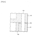
- a crankcase 101 made of cast iron and a cylinder head 102 made of cast iron are fixed to each other with a gasket 103 made of carbon steel (for example, a SS400 equivalent steel, an SPCC (JIS G3141) or the like) interposed in between by tightening a clamp bolt 104.
- a gasket 103 made of carbon steel for example, a SS400 equivalent steel, an SPCC (JIS G3141) or the like
- reference numeral 105 in Fig. 4 denotes a liner.
- crankcase 101 and the cylinder head 102 are worn as described above, the crankcase 101 and the cylinder head 102 are discarded to be replaced with new ones.
- the replacement results not only in waste of resources but also in high costs.
- Such a problem is not limited to the crankcase 101 and the cylinder head 102 of the diesel engine described above, and may similarly arise regarding any member made of a metal material.
- an object of the present invention is to provide a method of repairing a member, the method allowing reuse of a worn member made of a metal material.
- a method of repairing a member according to a first aspect of the invention for solving the above-described problems is a method of repairing a worn member made of metal, the method characterized by comprising: forming a bond layer by thermally spraying an Ni-Al alloy onto a worn portion of the member; and then, forming a buildup layer by thermally spraying a stainless steel onto the bond layer.
- a method of repairing a member according to a second aspect of the present invention in view of the first aspect of the present invention is characterized in that the member is made of cast iron.
- a method of repairing a member according to a third aspect of the present invention in view of the first aspect or the second aspect of the present invention is characterized in that the stainless steel is a Cr stainless steel.
- a method of repairing a member according to a fourth aspect of the present invention in view of any one of the first aspect to the third aspect of the present invention is characterized in that the buildup layer has a thickness of 0.1 mm to 3 mm.
- a method of repairing a member according to a fifth aspect of the present invention in view of any one of the first aspect to the fourth aspect of the present invention is characterized in that thermal spraying is performed by an arc wire spraying method.
- a method of repairing a member according to a sixth aspect of the present invention in view of any one of the first aspect to the fifth aspect of the present invention is characterized in that the member is a member forming an internal combustion engine.
- the buildup layer is formed with the bond layer interposed between the buildup layer and the member. Accordingly, the buildup layer can be firmly and closely attached to the bond layer, and thus detachment of the buildup layer can be reliably prevented. Consequently, it is possible to reuse the worn member.
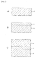
- FIG. 1 is a diagram illustrating repairing procedures of the method of repairing a member.
- Fig. 2 is a schematic configuration diagram of a main part of an arc wire welder.
- the method of repairing a member according to the present invention is a method of repairing a member 10 made of cast iron as a metal material and having been worn, as shown in Fig. 1 (see Fig. 1A ) .
- a Ni-Al alloy is thermally sprayed onto a worn portion of the member 10 by an arc wire spraying method so as to form a bond layer 11 (see Fig. 1B ).
- a Cr stainless steel is thermally sprayed onto the bond layer 11 by the arc wire spraying method so as to form a buildup layer 12 (see Fig. 1C ).
- the arc wire spraying method is implemented as shown in Fig. 2 .
- a pair of wires 1 made of a material to be thermally sprayed is fed from respective base ends of a pair of wire guide nozzles 3 to respective tip ends thereof by using two pairs of wire feed rolls 2, and then brought into contact with each other.
- a direct current voltage is applied between the paired wire guide nozzles 3.
- an arc is generated at the tip ends of the wires 1 brought into contact with each other, and the tip ends of the wires 1 are melted.
- the melted material of the wires 1 are thermally sprayed onto a thermal sprayed body 6 by injecting compressed air 5 from an air nozzle 4, and thus a thermal sprayed layer 7 is formed.
- the buildup layer 12 can be firmly and closely attached to the bond layer 11. Therefore, detachment of the buildup layer 12 can be reliably prevented.
- the aforementioned repairing is performed on, for example, the worn portions in the case described in Background Art in which the portions of the crankcase 101 (made of cast iron) and the cylinder head 102 (made of cast iron) in the diesel engine, which is an internal combustion engine, are worn due to the friction with the gasket 103 (made of a carbon steel (for example, made of a SS400 equivalent steel, an SPCC (JIS G3141) or the like)).
- the gasket 103 made of a carbon steel (for example, made of a SS400 equivalent steel, an SPCC (JIS G3141) or the like)
- the worn member 10 can be reused.
- the thickness of the buildup layer 12 may be appropriately set depending on the needs.
- the thickness is preferably set within a range of 0.1 mm to 3 mm. This is because a thickness of less than 0.1 mm is too thin and the bond layer 11 might be exposed, while a thickness of more than 3 mm is likely to cause a transverse crack and to thereby deteriorate the adhesion.
- the thickness of the bond layer 11 is preferably set to be approximately 0.1 mm. This is because the thickness significantly less than 0.1 mm is likely to cause a base material of the member 10 to be exposed and to thereby inhibit the bond layer 11 from exhibiting its function, while the thickness significantly larger than 0.1 mm results in waste of the material of the bond layer 11.
- a Cr stainless steel is thermally sprayed to form the buildup layer 12 and thereby the member 10 is repaired.
- the present invention is not limited to this.
- another stainless steel such as a Cr-Ni stainless steel may be thermally sprayed to form a buildup layer, and thereby a member may be repaired.
- the present invention is not limited to this.
- a member such as a crankcase and a cylinder head, which is worn in, for example, a gasoline engine which is another internal combustion engine
- the present invention can be applied to the case in the same manner as in the case of the embodiment described above.
- a worn member made of cast iron it is possible to obtain the same operations and effects as in the case of the embodiment described above at a significant level.
- Ni-Al alloy was thermally sprayed onto a base material made of a cast iron (FC250) by the arc wire spraying method to form a bond layer (thickness: 0.1mm). Thereafter, a Cr stainless steel (13Cr stainless steel (SUS 410)) was thermally sprayed by the arc wire spraying method to form a buildup layer (thickness: 0.1 mm to 6 mm). Thereby, various test pieces having the buildup layers with different thicknesses were prepared. Note that the size of the base materials was changed as appropriate, depending on the thickness of the buildup layer.
- a base material having a thickness of 1.4 mm, a length of 40 mm and a width of 3 mm was used.
- a base material having a thickness of 4 mm, a length of 100 mm and a width of 15 mm was used.
- a base material having a thickness of 16 mm, a length of 150 mm and a width of 50 mm was used.
- a strain meter is arranged on a buildup layer of a test piece. After both ends of the test piece on the buildup layer side are held, a load is gradually applied to a center portion of the test piece on the base material side (three-point bending test). Then, a strain distribution upon occurrence of a transverse crack in the buildup layer was found, while a tip end position of the transverse crack was determined by observation of a cross-sectional microstructure of the test piece, and a surface strain (detachment limit strain) at the tip end position was calculated. Note that the limit of the strain measurement was set to 1.2% (because the strain of this value or larger causes a crack in the base material, and thereby should not be taken into consideration).
- Fig. 3 shows a relationship between the detachment limit strains obtained by the above-described test method and the thicknesses of the buildup layer.
- the thickness of the buildup layer was 3 mm or less, even the strain of 1.2% did not cause a transverse crack in the buildup layer.
- the thickness of the buildup layer exceeded 3 mm, a trend was observed that the detachment limit strain gradually decreases less than 1.2%. Therefore, it was confirmed that, when the thickness of the buildup layer is 3 mm or less, the buildup layer can be firmly and closely attached to the base material, and detachment of the buildup layer from the base material can be reliably prevented.
- the method of repairing a member according to the present invention allows reuse of a worn member, and thus can be utilized extremely usefully in various industries.
Landscapes
- Chemical & Material Sciences (AREA)
- Engineering & Computer Science (AREA)
- Physics & Mathematics (AREA)
- Plasma & Fusion (AREA)
- Chemical Kinetics & Catalysis (AREA)
- Materials Engineering (AREA)
- Mechanical Engineering (AREA)
- Metallurgy (AREA)
- Organic Chemistry (AREA)
- Coating By Spraying Or Casting (AREA)
- Cylinder Crankcases Of Internal Combustion Engines (AREA)
Claims (4)
- Procédé de réparation d'un élément usé (10) fabriqué en métal, le procédé comportant le fait de :former une couche de liaison (11) en projetant thermiquement un alliage Ni-Al sur une partie usée de l'élément, ledit élément étant un carter ou une culasse d'un moteur diesel fabriqué en fonte, ladite partie étant en contact avec une chemise ; et ensuite,former une couche d'accumulation (12) en projetant thermiquement un acier inoxydable sur la couche de liaison (11).
- Procédé de réparation d'un élément (10) selon la revendication 1, caractérisé en ce que l'acier inoxydable est un acier inoxydable au chrome.
- Procédé de réparation d'un élément (10) selon la revendication 1 ou 2, caractérisé en ce que la couche d'accumulation (12) a une épaisseur de 0,1 mm à 3 mm.
- Procédé de réparation d'un élément (10) selon l'une quelconque des revendications 1 à 3, caractérisé en ce qu'une projection thermique est réalisée par un procédé de projection à fil à l'arc.
Applications Claiming Priority (2)
| Application Number | Priority Date | Filing Date | Title |
|---|---|---|---|
| JP2008070564A JP5155706B2 (ja) | 2008-03-19 | 2008-03-19 | 部材の補修方法 |
| PCT/JP2008/066376 WO2009116193A1 (fr) | 2008-03-19 | 2008-09-11 | Procédé de réparation d'un élément |
Publications (3)
| Publication Number | Publication Date |
|---|---|
| EP2256227A1 EP2256227A1 (fr) | 2010-12-01 |
| EP2256227A4 EP2256227A4 (fr) | 2011-03-09 |
| EP2256227B1 true EP2256227B1 (fr) | 2013-08-21 |
Family
ID=41090610
Family Applications (1)
| Application Number | Title | Priority Date | Filing Date |
|---|---|---|---|
| EP08873381.1A Not-in-force EP2256227B1 (fr) | 2008-03-19 | 2008-09-11 | Procédé de réparation d'un élément |
Country Status (5)
| Country | Link |
|---|---|
| US (1) | US20110138596A1 (fr) |
| EP (1) | EP2256227B1 (fr) |
| JP (1) | JP5155706B2 (fr) |
| CN (1) | CN101978090A (fr) |
| WO (1) | WO2009116193A1 (fr) |
Families Citing this family (8)
| Publication number | Priority date | Publication date | Assignee | Title |
|---|---|---|---|---|
| ITTO20120537A1 (it) * | 2012-06-19 | 2013-12-20 | Avio Spa | Procedimento per depositare materiale su una superficie di un pezzo, in particolare per riparare tale pezzo |
| CN102877017A (zh) * | 2012-08-16 | 2013-01-16 | 沈阳黎明航空发动机(集团)有限责任公司 | 一种航空发动机附件机匣壳体损伤端面热喷涂再制造方法 |
| US9067282B2 (en) * | 2013-05-14 | 2015-06-30 | Caterpillar Inc. | Remanufacturing cast iron component with steel outer layer and remanufactured component |
| CN104911530A (zh) * | 2015-05-15 | 2015-09-16 | 潘洁萍 | 糖机的底梳、面梳提高耐磨性的方法 |
| CN104907760A (zh) * | 2015-05-15 | 2015-09-16 | 潘洁萍 | 一种榨糖机的榨辊轴颈磨损的修复方法 |
| CN107164714A (zh) * | 2017-04-28 | 2017-09-15 | 广西大学 | 一种含钛复合板的修补方法 |
| US20230064090A1 (en) * | 2021-08-26 | 2023-03-02 | Valmet Aktiebolag | Method of applying a wear-resistant coating on a yankee drying cylinder, such coatings and yankee cylinders with such coatings |
| US20230065043A1 (en) * | 2021-08-26 | 2023-03-02 | Valmet Aktiebolag | Method of applying a wear-resistant coating on a yankee drying cylinder |
Family Cites Families (16)
| Publication number | Priority date | Publication date | Assignee | Title |
|---|---|---|---|---|
| US3715790A (en) * | 1971-01-13 | 1973-02-13 | Trw Inc | Method of reinforcing piston ring grooves |
| FR2382509A1 (fr) * | 1976-12-21 | 1978-09-29 | Eutectic Corp | Application a la flamme d'un revetement metallique sur un organe de forme cylindrique, notamment rouleau secheur |
| US4724819A (en) * | 1987-01-23 | 1988-02-16 | Precision National Plating Services, Inc. | Cylinder liner reconditioning process and cylinder liner produced thereby |
| JPH05302674A (ja) | 1992-04-27 | 1993-11-16 | Riken Corp | ピストンリングとシリンダの組合せ |
| JP3335744B2 (ja) | 1993-12-29 | 2002-10-21 | 帝国ピストンリング株式会社 | 摺動部材の組合せ |
| JPH08145092A (ja) * | 1994-11-17 | 1996-06-04 | Yoshino Giken Kk | ディスクロータ |
| JP3547583B2 (ja) | 1997-04-30 | 2004-07-28 | 財団法人シップ・アンド・オーシャン財団 | シリンダーライナー |
| JP2000022057A (ja) * | 1998-06-30 | 2000-01-21 | Sumitomo Metal Electronics Devices Inc | 放熱用金属板およびそれを用いた電子部品用パッケージ |
| JP4342700B2 (ja) * | 2000-07-10 | 2009-10-14 | 株式会社東芝 | 電気機器用コーティング部材及びその製造方法 |
| JP2002167679A (ja) * | 2000-11-30 | 2002-06-11 | Kyocera Corp | セラミック基材表面の溶射皮膜 |
| JP3612568B2 (ja) * | 2001-10-09 | 2005-01-19 | 独立行政法人物質・材料研究機構 | Hvof溶射ガンによる金属皮膜形成方法と溶射装置 |
| WO2004033747A1 (fr) * | 2002-10-09 | 2004-04-22 | National Institute For Materials Science | Procede de realisation d'un revetement metallique avec un canon projecteur d'oxygaz grande vitesse, et appareil de projection a chaud |
| JP2004256913A (ja) | 2003-02-07 | 2004-09-16 | Nippon Piston Ring Co Ltd | Cr−Mo合金めっき被膜 |
| DE10308563B3 (de) * | 2003-02-27 | 2004-08-19 | Federal-Mogul Burscheid Gmbh | Zylinderlaufbuchse mit Verschleißschutzbeschichtung, ihre Herstellung und ihre Verwendung |
| DE10324279B4 (de) * | 2003-05-28 | 2006-04-06 | Daimlerchrysler Ag | Verwendung von FeC-Legierung zur Erneuerung der Oberfläche von Zylinderlaufbuchsen |
| DE102004026395A1 (de) * | 2004-05-29 | 2005-12-22 | Elringklinger Ag | Zylinderkopfdichtung |
-
2008
- 2008-03-19 JP JP2008070564A patent/JP5155706B2/ja not_active Expired - Fee Related
- 2008-09-11 WO PCT/JP2008/066376 patent/WO2009116193A1/fr not_active Ceased
- 2008-09-11 US US12/920,994 patent/US20110138596A1/en not_active Abandoned
- 2008-09-11 CN CN2008801281965A patent/CN101978090A/zh active Pending
- 2008-09-11 EP EP08873381.1A patent/EP2256227B1/fr not_active Not-in-force
Also Published As
| Publication number | Publication date |
|---|---|
| US20110138596A1 (en) | 2011-06-16 |
| JP5155706B2 (ja) | 2013-03-06 |
| EP2256227A4 (fr) | 2011-03-09 |
| CN101978090A (zh) | 2011-02-16 |
| JP2009221587A (ja) | 2009-10-01 |
| WO2009116193A1 (fr) | 2009-09-24 |
| EP2256227A1 (fr) | 2010-12-01 |
Similar Documents
| Publication | Publication Date | Title |
|---|---|---|
| EP2256227B1 (fr) | Procédé de réparation d'un élément | |
| US8845501B2 (en) | Process for producing a roll for supporting and conveying hot material, process for repairing a worn roll | |
| EP3590645B1 (fr) | Procédé de soudage par points par résistance | |
| CN107287473A (zh) | 堆焊用合金粉末和使用该合金粉末的发动机阀的制造方法 | |
| KR20150046222A (ko) | 필렛 아크 용접 조인트의 형성 방법 및 필렛 아크 용접 조인트 | |
| Shtayger et al. | Investigation of macro and micro structures of compounds of high-strength rails implemented by contact butt welding using burning-off | |
| JP2010201491A (ja) | 耐熱鋼品の溶接補修方法及び溶接補修部を有する耐熱鋼品 | |
| US20200224317A1 (en) | Piston ring with shot-peened running-in layer and method for the production thereof | |
| JP4984214B2 (ja) | シリンダブロック用鉄系溶射薄膜及びシリンダブロック | |
| EP2861776B1 (fr) | Composant reconstruit et fil pour projection thermique de fealsic pour celui-ci | |
| JP2017217684A (ja) | 連続鋳造鋳型の補修方法 | |
| EP3385532B1 (fr) | Tuyau d'injection de carburant haute pression pourvu d'une partie tête de raccordement et procédé de moulage de partie tête de raccordement | |
| JP7296985B2 (ja) | 抵抗スポット溶接方法、および抵抗スポット溶接継手の製造方法 | |
| JP6828831B1 (ja) | 抵抗スポット溶接方法、抵抗スポット溶接継手の製造方法 | |
| JP2021074737A (ja) | 抵抗スポット溶接継手の製造方法 | |
| JP6593033B2 (ja) | 重ね溶接継手の製造方法 | |
| JPH11172408A (ja) | 摩耗対策用ライニング材およびその施工方法 | |
| KR20110052178A (ko) | 선박용 디젤엔진의 실린더커버 고온 부식 방지를 위한 인코넬 열용사 코팅 방법 | |
| US11376688B2 (en) | Friction stir welding tool | |
| RU187769U1 (ru) | Силовое соединение осей для рельсовых транспортных средств со ступицами элементов трансмиссии | |
| Ren et al. | Failure analysis on magnetic ring of an elevator brake | |
| CZ32399U1 (cs) | Silové spojení náprav kolejových vozidel s náboji přenosových prvků | |
| Kończewicz et al. | Study of structures and properties of the laser cladding exhaust valve after service | |
| Azarmi et al. | Investigation of Mechanical Properties of Twin Wire Arc Repair of Cast Iron Components | |
| Ahn et al. | A Study of the Affected Layer and Stress Corrosion Crack of Ultra-high-strength Steel (300M) for Aircraft Parts |
Legal Events
| Date | Code | Title | Description |
|---|---|---|---|
| PUAI | Public reference made under article 153(3) epc to a published international application that has entered the european phase |
Free format text: ORIGINAL CODE: 0009012 |
|
| 17P | Request for examination filed |
Effective date: 20100917 |
|
| AK | Designated contracting states |
Kind code of ref document: A1 Designated state(s): AT BE BG CH CY CZ DE DK EE ES FI FR GB GR HR HU IE IS IT LI LT LU LV MC MT NL NO PL PT RO SE SI SK TR |
|
| AX | Request for extension of the european patent |
Extension state: AL BA MK RS |
|
| A4 | Supplementary search report drawn up and despatched |
Effective date: 20110204 |
|
| RIC1 | Information provided on ipc code assigned before grant |
Ipc: C23C 4/08 20060101ALI20110201BHEP Ipc: F02F 1/00 20060101ALI20110201BHEP Ipc: B23P 6/00 20060101ALI20110201BHEP Ipc: C23C 4/12 20060101ALI20110201BHEP Ipc: C23C 4/06 20060101AFI20091009BHEP |
|
| DAX | Request for extension of the european patent (deleted) | ||
| GRAP | Despatch of communication of intention to grant a patent |
Free format text: ORIGINAL CODE: EPIDOSNIGR1 |
|
| INTG | Intention to grant announced |
Effective date: 20130424 |
|
| GRAS | Grant fee paid |
Free format text: ORIGINAL CODE: EPIDOSNIGR3 |
|
| GRAA | (expected) grant |
Free format text: ORIGINAL CODE: 0009210 |
|
| AK | Designated contracting states |
Kind code of ref document: B1 Designated state(s): AT BE BG CH CY CZ DE DK EE ES FI FR GB GR HR HU IE IS IT LI LT LU LV MC MT NL NO PL PT RO SE SI SK TR |
|
| REG | Reference to a national code |
Ref country code: GB Ref legal event code: FG4D |
|
| REG | Reference to a national code |
Ref country code: CH Ref legal event code: EP |
|
| REG | Reference to a national code |
Ref country code: AT Ref legal event code: REF Ref document number: 628159 Country of ref document: AT Kind code of ref document: T Effective date: 20130915 |
|
| REG | Reference to a national code |
Ref country code: IE Ref legal event code: FG4D |
|
| REG | Reference to a national code |
Ref country code: DE Ref legal event code: R096 Ref document number: 602008027086 Country of ref document: DE Effective date: 20131017 |
|
| REG | Reference to a national code |
Ref country code: NL Ref legal event code: VDEP Effective date: 20130821 |
|
| REG | Reference to a national code |
Ref country code: LT Ref legal event code: MG4D |
|
| PG25 | Lapsed in a contracting state [announced via postgrant information from national office to epo] |
Ref country code: LT Free format text: LAPSE BECAUSE OF FAILURE TO SUBMIT A TRANSLATION OF THE DESCRIPTION OR TO PAY THE FEE WITHIN THE PRESCRIBED TIME-LIMIT Effective date: 20130821 Ref country code: PT Free format text: LAPSE BECAUSE OF FAILURE TO SUBMIT A TRANSLATION OF THE DESCRIPTION OR TO PAY THE FEE WITHIN THE PRESCRIBED TIME-LIMIT Effective date: 20131223 Ref country code: NO Free format text: LAPSE BECAUSE OF FAILURE TO SUBMIT A TRANSLATION OF THE DESCRIPTION OR TO PAY THE FEE WITHIN THE PRESCRIBED TIME-LIMIT Effective date: 20131121 Ref country code: HR Free format text: LAPSE BECAUSE OF FAILURE TO SUBMIT A TRANSLATION OF THE DESCRIPTION OR TO PAY THE FEE WITHIN THE PRESCRIBED TIME-LIMIT Effective date: 20130821 Ref country code: CY Free format text: LAPSE BECAUSE OF FAILURE TO SUBMIT A TRANSLATION OF THE DESCRIPTION OR TO PAY THE FEE WITHIN THE PRESCRIBED TIME-LIMIT Effective date: 20130911 Ref country code: SE Free format text: LAPSE BECAUSE OF FAILURE TO SUBMIT A TRANSLATION OF THE DESCRIPTION OR TO PAY THE FEE WITHIN THE PRESCRIBED TIME-LIMIT Effective date: 20130821 Ref country code: IS Free format text: LAPSE BECAUSE OF FAILURE TO SUBMIT A TRANSLATION OF THE DESCRIPTION OR TO PAY THE FEE WITHIN THE PRESCRIBED TIME-LIMIT Effective date: 20131221 |
|
| PG25 | Lapsed in a contracting state [announced via postgrant information from national office to epo] |
Ref country code: PL Free format text: LAPSE BECAUSE OF FAILURE TO SUBMIT A TRANSLATION OF THE DESCRIPTION OR TO PAY THE FEE WITHIN THE PRESCRIBED TIME-LIMIT Effective date: 20130821 Ref country code: BE Free format text: LAPSE BECAUSE OF FAILURE TO SUBMIT A TRANSLATION OF THE DESCRIPTION OR TO PAY THE FEE WITHIN THE PRESCRIBED TIME-LIMIT Effective date: 20130821 Ref country code: GR Free format text: LAPSE BECAUSE OF FAILURE TO SUBMIT A TRANSLATION OF THE DESCRIPTION OR TO PAY THE FEE WITHIN THE PRESCRIBED TIME-LIMIT Effective date: 20131122 Ref country code: LV Free format text: LAPSE BECAUSE OF FAILURE TO SUBMIT A TRANSLATION OF THE DESCRIPTION OR TO PAY THE FEE WITHIN THE PRESCRIBED TIME-LIMIT Effective date: 20130821 Ref country code: SI Free format text: LAPSE BECAUSE OF FAILURE TO SUBMIT A TRANSLATION OF THE DESCRIPTION OR TO PAY THE FEE WITHIN THE PRESCRIBED TIME-LIMIT Effective date: 20130821 Ref country code: FI Free format text: LAPSE BECAUSE OF FAILURE TO SUBMIT A TRANSLATION OF THE DESCRIPTION OR TO PAY THE FEE WITHIN THE PRESCRIBED TIME-LIMIT Effective date: 20130821 |
|
| PG25 | Lapsed in a contracting state [announced via postgrant information from national office to epo] |
Ref country code: CY Free format text: LAPSE BECAUSE OF FAILURE TO SUBMIT A TRANSLATION OF THE DESCRIPTION OR TO PAY THE FEE WITHIN THE PRESCRIBED TIME-LIMIT Effective date: 20130821 |
|
| PG25 | Lapsed in a contracting state [announced via postgrant information from national office to epo] |
Ref country code: SK Free format text: LAPSE BECAUSE OF FAILURE TO SUBMIT A TRANSLATION OF THE DESCRIPTION OR TO PAY THE FEE WITHIN THE PRESCRIBED TIME-LIMIT Effective date: 20130821 Ref country code: RO Free format text: LAPSE BECAUSE OF FAILURE TO SUBMIT A TRANSLATION OF THE DESCRIPTION OR TO PAY THE FEE WITHIN THE PRESCRIBED TIME-LIMIT Effective date: 20130821 Ref country code: DK Free format text: LAPSE BECAUSE OF FAILURE TO SUBMIT A TRANSLATION OF THE DESCRIPTION OR TO PAY THE FEE WITHIN THE PRESCRIBED TIME-LIMIT Effective date: 20130821 Ref country code: EE Free format text: LAPSE BECAUSE OF FAILURE TO SUBMIT A TRANSLATION OF THE DESCRIPTION OR TO PAY THE FEE WITHIN THE PRESCRIBED TIME-LIMIT Effective date: 20130821 Ref country code: CZ Free format text: LAPSE BECAUSE OF FAILURE TO SUBMIT A TRANSLATION OF THE DESCRIPTION OR TO PAY THE FEE WITHIN THE PRESCRIBED TIME-LIMIT Effective date: 20130821 Ref country code: NL Free format text: LAPSE BECAUSE OF FAILURE TO SUBMIT A TRANSLATION OF THE DESCRIPTION OR TO PAY THE FEE WITHIN THE PRESCRIBED TIME-LIMIT Effective date: 20130821 |
|
| REG | Reference to a national code |
Ref country code: CH Ref legal event code: PL |
|
| PG25 | Lapsed in a contracting state [announced via postgrant information from national office to epo] |
Ref country code: IT Free format text: LAPSE BECAUSE OF FAILURE TO SUBMIT A TRANSLATION OF THE DESCRIPTION OR TO PAY THE FEE WITHIN THE PRESCRIBED TIME-LIMIT Effective date: 20130821 Ref country code: MC Free format text: LAPSE BECAUSE OF FAILURE TO SUBMIT A TRANSLATION OF THE DESCRIPTION OR TO PAY THE FEE WITHIN THE PRESCRIBED TIME-LIMIT Effective date: 20130821 Ref country code: ES Free format text: LAPSE BECAUSE OF FAILURE TO SUBMIT A TRANSLATION OF THE DESCRIPTION OR TO PAY THE FEE WITHIN THE PRESCRIBED TIME-LIMIT Effective date: 20130821 |
|
| PLBE | No opposition filed within time limit |
Free format text: ORIGINAL CODE: 0009261 |
|
| STAA | Information on the status of an ep patent application or granted ep patent |
Free format text: STATUS: NO OPPOSITION FILED WITHIN TIME LIMIT |
|
| REG | Reference to a national code |
Ref country code: IE Ref legal event code: MM4A |
|
| 26N | No opposition filed |
Effective date: 20140522 |
|
| PG25 | Lapsed in a contracting state [announced via postgrant information from national office to epo] |
Ref country code: IE Free format text: LAPSE BECAUSE OF NON-PAYMENT OF DUE FEES Effective date: 20130911 Ref country code: CH Free format text: LAPSE BECAUSE OF NON-PAYMENT OF DUE FEES Effective date: 20130930 Ref country code: LI Free format text: LAPSE BECAUSE OF NON-PAYMENT OF DUE FEES Effective date: 20130930 |
|
| REG | Reference to a national code |
Ref country code: DE Ref legal event code: R097 Ref document number: 602008027086 Country of ref document: DE Effective date: 20140522 |
|
| PG25 | Lapsed in a contracting state [announced via postgrant information from national office to epo] |
Ref country code: MT Free format text: LAPSE BECAUSE OF FAILURE TO SUBMIT A TRANSLATION OF THE DESCRIPTION OR TO PAY THE FEE WITHIN THE PRESCRIBED TIME-LIMIT Effective date: 20130821 Ref country code: TR Free format text: LAPSE BECAUSE OF FAILURE TO SUBMIT A TRANSLATION OF THE DESCRIPTION OR TO PAY THE FEE WITHIN THE PRESCRIBED TIME-LIMIT Effective date: 20130821 |
|
| PG25 | Lapsed in a contracting state [announced via postgrant information from national office to epo] |
Ref country code: LU Free format text: LAPSE BECAUSE OF NON-PAYMENT OF DUE FEES Effective date: 20130911 Ref country code: HU Free format text: LAPSE BECAUSE OF FAILURE TO SUBMIT A TRANSLATION OF THE DESCRIPTION OR TO PAY THE FEE WITHIN THE PRESCRIBED TIME-LIMIT; INVALID AB INITIO Effective date: 20080911 Ref country code: BG Free format text: LAPSE BECAUSE OF FAILURE TO SUBMIT A TRANSLATION OF THE DESCRIPTION OR TO PAY THE FEE WITHIN THE PRESCRIBED TIME-LIMIT Effective date: 20130821 |
|
| REG | Reference to a national code |
Ref country code: FR Ref legal event code: PLFP Year of fee payment: 9 |
|
| REG | Reference to a national code |
Ref country code: FR Ref legal event code: PLFP Year of fee payment: 10 |
|
| PGFP | Annual fee paid to national office [announced via postgrant information from national office to epo] |
Ref country code: DE Payment date: 20170905 Year of fee payment: 10 Ref country code: GB Payment date: 20170906 Year of fee payment: 10 Ref country code: FR Payment date: 20170810 Year of fee payment: 10 |
|
| PGFP | Annual fee paid to national office [announced via postgrant information from national office to epo] |
Ref country code: AT Payment date: 20170825 Year of fee payment: 10 |
|
| REG | Reference to a national code |
Ref country code: DE Ref legal event code: R119 Ref document number: 602008027086 Country of ref document: DE |
|
| REG | Reference to a national code |
Ref country code: AT Ref legal event code: MM01 Ref document number: 628159 Country of ref document: AT Kind code of ref document: T Effective date: 20180911 |
|
| GBPC | Gb: european patent ceased through non-payment of renewal fee |
Effective date: 20180911 |
|
| PG25 | Lapsed in a contracting state [announced via postgrant information from national office to epo] |
Ref country code: DE Free format text: LAPSE BECAUSE OF NON-PAYMENT OF DUE FEES Effective date: 20190402 |
|
| PG25 | Lapsed in a contracting state [announced via postgrant information from national office to epo] |
Ref country code: FR Free format text: LAPSE BECAUSE OF NON-PAYMENT OF DUE FEES Effective date: 20180930 |
|
| PG25 | Lapsed in a contracting state [announced via postgrant information from national office to epo] |
Ref country code: GB Free format text: LAPSE BECAUSE OF NON-PAYMENT OF DUE FEES Effective date: 20180911 Ref country code: AT Free format text: LAPSE BECAUSE OF NON-PAYMENT OF DUE FEES Effective date: 20180911 |