EP2256273A2 - Crémone-serrure de verrouillage multi-points - Google Patents
Crémone-serrure de verrouillage multi-points Download PDFInfo
- Publication number
- EP2256273A2 EP2256273A2 EP10003763A EP10003763A EP2256273A2 EP 2256273 A2 EP2256273 A2 EP 2256273A2 EP 10003763 A EP10003763 A EP 10003763A EP 10003763 A EP10003763 A EP 10003763A EP 2256273 A2 EP2256273 A2 EP 2256273A2
- Authority
- EP
- European Patent Office
- Prior art keywords
- lock
- central
- locking
- additional
- chain
- Prior art date
- Legal status (The legal status is an assumption and is not a legal conclusion. Google has not performed a legal analysis and makes no representation as to the accuracy of the status listed.)
- Withdrawn
Links
Images
Classifications
-
- E—FIXED CONSTRUCTIONS
- E05—LOCKS; KEYS; WINDOW OR DOOR FITTINGS; SAFES
- E05B—LOCKS; ACCESSORIES THEREFOR; HANDCUFFS
- E05B63/00—Locks or fastenings with special structural characteristics
- E05B63/18—Locks or fastenings with special structural characteristics with arrangements independent of the locking mechanism for retaining the bolt or latch in the retracted position
- E05B63/20—Locks or fastenings with special structural characteristics with arrangements independent of the locking mechanism for retaining the bolt or latch in the retracted position released automatically when the wing is closed
-
- E—FIXED CONSTRUCTIONS
- E05—LOCKS; KEYS; WINDOW OR DOOR FITTINGS; SAFES
- E05C—BOLTS OR FASTENING DEVICES FOR WINGS, SPECIALLY FOR DOORS OR WINDOWS
- E05C9/00—Arrangements of simultaneously actuated bolts or other securing devices at well-separated positions on the same wing
- E05C9/02—Arrangements of simultaneously actuated bolts or other securing devices at well-separated positions on the same wing with one sliding bar for fastening when moved in one direction and unfastening when moved in opposite direction; with two sliding bars moved in the same direction when fastening or unfastening
- E05C9/026—Arrangements of simultaneously actuated bolts or other securing devices at well-separated positions on the same wing with one sliding bar for fastening when moved in one direction and unfastening when moved in opposite direction; with two sliding bars moved in the same direction when fastening or unfastening comprising key-operated locks, e.g. a lock cylinder to drive auxiliary deadbolts or latch bolts
-
- E—FIXED CONSTRUCTIONS
- E05—LOCKS; KEYS; WINDOW OR DOOR FITTINGS; SAFES
- E05C—BOLTS OR FASTENING DEVICES FOR WINGS, SPECIALLY FOR DOORS OR WINDOWS
- E05C9/00—Arrangements of simultaneously actuated bolts or other securing devices at well-separated positions on the same wing
- E05C9/18—Details of fastening means or of fixed retaining means for the ends of bars
- E05C9/1825—Fastening means
- E05C9/1875—Fastening means performing pivoting movements
-
- E—FIXED CONSTRUCTIONS
- E05—LOCKS; KEYS; WINDOW OR DOOR FITTINGS; SAFES
- E05B—LOCKS; ACCESSORIES THEREFOR; HANDCUFFS
- E05B59/00—Locks with latches separate from the lock-bolts or with a plurality of latches or lock-bolts
Definitions
- the invention relates to a drive rod lock with multiple locking, with at least one central lock with at least one central bolt and a (in a central lock housing) displaceable central lock chain and with at least one self-locking toastverrieglung with an additional bolt and a (in an additional lock housing) sliding auxiliary lock chain, wherein the central lock is connected via at least one drive rod with the additional locking and the additional bolt with the central lock on the drive rod and the auxiliary lock chain from a locking position into an unlocking position can be transferred and wherein the additional bolt automatically transferred in closing position-reaching door by moving the auxiliary lock chain automatically into the locking position becomes.
- the central lock can in particular be a push-button and / or key-operated central lock with lock nut.
- Additional bolt of additional locking means, for example, a bolt, a latch bolt, a trap or a swivel hook.
- Such a locking element of the additional locking should be transferred automatically in the closed position reaching door leaf in the locked position and thus be automatically excluded, so that at zu fallendem door an automatic locking (the Rajverrieglungen) takes place.
- the triggering can take place, for example, by a release magnet which can be mounted in the region of a door frame-side closing strip and for automatic locking on a locking element arranged in the additional locking element works, so that this locking element releases the lock chain of Rajverrieglung and thereby the additional lock is automatically transferred to the locking position.
- the blocking element is designed as a linearly displaceable locking pin, which is attracted to unlock the auxiliary lock chain of the release magnet.
- the release magnet is designed as a permanent magnet.
- the invention has for its object to provide a drive rod lock with Mehrfachverrieglung of the type described above, which is characterized by increased functionality and in particular safety.
- the invention teaches in a generic espagnolette with Mehrfachverrieglung the type described above, the additional lock chain of Rajverrieglung on the drive rod on the central lock chain works and this (centrate lock chain) in the course of self-locking the additional lock (also) the central latch of the central lock from the Entriegelungs ein transferred to the locking position.
- the invention proposes in a preferred embodiment that the central lock chain via a locking lever, preferably pivotally mounted in the central lock housing locking lever, works on the central latch.
- the locking lever can implement a displacement of the central lock chain in the drive rod longitudinal direction in a displacement of the central bar in a direction transverse to the drive rod longitudinal direction locking direction.
- the invention is based on the recognition that functionality and safety of a known espagnolette with multiple locking and self-locking can be increased if not only a self-locking of additional locks or additional locks takes place in the closed position reaching door, but also a self-locking of the central lock.
- door leaf When reaching in the closed position door leaf consequently not only the additional bolt of the additional locks, but in particular the central bolt of the central lock are excluded.
- Particularly preferred all locking elements of the espagnolette lock are excluded in the course of self-locking.
- the additional lock chain of the additional locking is coupled in the context of the invention via the respective drive rod to the central lock chain of the central lock.
- the additional lock chain is transferred in the course of self-locking by gravity and / or spring force (for example, a locking spring) from the unlocked position into the locking position, so that on the additional lock chain initially in a conventional manner and the additional latch from the unlocked position into the locked position is transferred.
- This gravity and / or spring-loaded transfer of additional lock chain and additional latch from the unlocked position in the locked position is prevented (initially) via a blocking element.
- this blocking element for example a blocking pin
- the blocking element releases the auxiliary lock chain so that it (automatically) moves out of the unlocked position is transferred to the locking position and thus excludes the additional bolt.
- the respective drive rod is actuated in the transfer of the additional lock chain from the unlocked position into the locking position, which in turn is in operative connection with the central lock chain of the central lock.
- the central lock chain of the central lock is thus transferred from an unlocked position into a locking position, in particular moved. This displacement of the central lock chain in the drive rod longitudinal direction is then converted by the locking lever into a locking movement of the central bolt along the Verrieglungsraum.
- the locking lever in a preferred development, at least one control surface on which an actuating element of the central lock chain works.
- This actuator can be designed as connected to the lock chain actuating cam.
- the actuating cam is firmly connected to the lock chain, for example integrally formed on the lock chain.
- the control surface on the Verrieglungshebel is designed such that the locking lever is pivoted in the course of displacement of the actuating cam about the axis of rotation of the locking lever.
- the coupling of the Verrieglungshebels to the central bolt can be realized for example by a connected to the central bolt mandrel or cam, which engages, for example, in a fork seat of Verrieglungshebels. Basically, other couplings are conceivable.
- Verrieglungshebel works in the course of pivoting with a control surface on a corresponding actuating surface, for example the dome of the central bar.
- the embodiment described with fork mount has, for example, the advantage that a power transmission in "two directions" is ensured.
- optional could also be provided a slot guide or comparable recording on the locking lever.
- the invention proposes that the auxiliary lock chain is held by a blocking element in the unlocking position and that in or on a the additional lock associated door frame side closing bar a release magnet is arranged, which actuates the blocking element for automatic locking such that this releases the lock chain, so that the additional bolt (and thus on the drive rod and the central lock chain and the central latch) is automatically transferred to the locking position.
- the blocking element can be designed as a linearly displaceable locking pin and, for example, be moved towards the release magnet in an attractive sense for unlocking the auxiliary lock chain.
- the triggering magnet is preferably designed as a permanent magnet and the blocking element is preferably not permanent magnetically, but magnetizable, for example made of a ferromagnetic metal.
- the auxiliary lock chain is moved in the course of unlocking and locking in the auxiliary lock housing parallel to the lock plate, preferably vertically and consequently in drive rod longitudinal direction. By coupling the auxiliary lock chain via the drive rods to the central lock chain, then the central lock chain is moved in this direction. To Release by the blocking element, the additional lock chain (and thus on the espagnolettes on the central lock chain) is transferred by the gravity and / or the spring force of a locking spring from the unlocked position into the locking position.
- Such a locking spring can, for example, work on an intermediate lever in the auxiliary lock, this intermediate lever coupling the auxiliary lock chain to the auxiliary bolt.
- the intermediate lever may be formed in a manner known per se as pivotable on, for example, the auxiliary lock housing hinged pivot lever. In detail, reference is made to the embodiment in the figures.
- the invention also includes embodiments in which the self-locking additional latches are constructed differently. So also triggers are conceivable that do not work with a release magnet.
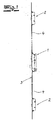
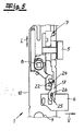
- Fig.1 shows an attachable to a door espagnolette lock, which as a locking units on the one hand, a central lock 1 and on the other hand, upper and lower additional latches 2, which are fixed to the back of a (common) lock plate 3.
- the central lock 1 may comprise, in a manner known per se, a latch 5, a central latch 6, a central lock chain 7, a lock nut 8 and a corresponding receptacle 9 for a lock cylinder.
- the lock chain 7 is arranged in drive rod longitudinal direction L in the lock housing 10 of the central lock.
- the additional latches 2 each have an additional latch 11, which is formed in the embodiment as a latch bolt. Furthermore, the additional latches 2 each have an additional lock chain 13 slidable in the auxiliary lock housing 12 in the drive rod longitudinal direction L.
- the central lock chain 7 and the associated drive rod 4 works on the attached additional lock chain 13 of the additional lock 2.
- the central lock chain of the central bar 6 is transferred from an excluded locking position into an enclosed unlocking position and vice versa.
- the latch bolt 11 of the additional lock 2 is transferred from an excluded locking position into an enclosed unlocking position and vice versa.
- the unlocking is usually carried out by actuation of the central lock 1 and consequently via the drive rod 4, which transfers the auxiliary lock chain 13 from the locking position into the unlocked position.
- the locking takes place at the Drive rod lock according to the invention automatically or automatically, as soon as the door or the door reaches the closed position.
- the auxiliary lock chain 13 is held by a blocking element 14 initially in the unlocked position and that in or on one of the additional locking 2 associated door frame-side closing strip 15, a release magnet 16 is arranged.
- This closing strip-side release magnet 16 operates for automatic locking or for automatic triggering on the locking element 14, which then releases the auxiliary lock chain 13, so that the auxiliary bolt 11 is transferred to the locking position.
- the auxiliary lock chain 13 operates on the drive rod 4 on the central lock chain 7, in such a way that in the course of self-locking the additional lock 2, the central latch 6 of the central lock 1 is transferred from the unlocked position to the locking position.
- a complete self-locking which relates to both the additional locks 2 and the central lock 1.
- the central lock chain 7 operates via a pivotally mounted in the central lock housing 10 locking lever 17 on the central latch 6.
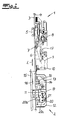
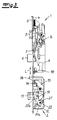
- Fig. 2 and 4 show the espagnolette lock in the unlocked position while Fig. 3 and 5 show the espagnolette lock in the locked position.
- the Fig. 4 and 5 show the central lock 1 from a different view than the Fig. 2 and 3 ,
- FIG. 2 A comparative analysis of the Fig. 2 and 3 first clarifies the self-locking mechanism for the additional lock 2.
- the trigger magnet 16 In the functional position according to Fig. 2 the trigger magnet 16 is far away from the espagnolette lock, so that it is the blocking element, which is formed in the embodiment as a linearly displaceable locking pin 14, not affected.
- the auxiliary lock chain 13 is on the one hand by gravity and on the other hand (indirectly) via a locking spring 19 from the unlocked position into the locking position transferred as soon as the Trigger magnet shifts the locking pin 14 and this releases the auxiliary lock chain 13.
- the coupling between the additional lock chain 13 and the auxiliary bolt 11 via an intermediate lever 20, which is designed as pivotable about the axis 21 hinged to the lock housing pivot lever.
- this intermediate lever is designed as an L-shaped lever 20.
- This has a first arm 20a, which is associated with the auxiliary lock chain 13 and a second arm 20b, which is associated with the auxiliary bolt 11.
- this intermediate lever 20 (indirectly) is acted upon by the locking spring 19.
- the locking springs 19 tends to push the latch bolt 11 in the locked position, such a lock is in the functional position according to Fig. 2 blocked because the auxiliary lock chain 13 is blocked via the locking pin 14 so that the connected to the auxiliary lock chain 13 intermediate lever 20 holds the latch bolt 11.
- the magnet 16 triggers the automatic locking, so that the locking pin 14 now releases the lock chain of the auxiliary lock 2, so that the additional bolt 13 via the gravity of the lock chain 13th and on the other hand is transferred via the spring force of the locking spring 20 in the locking position, in which the auxiliary bolt 13 is excluded (see. Fig. 3 or 5).
- the closing strip 15 is only in Fig. 2 indicated.
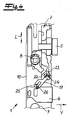
- the automatic locking is not limited to the additional lock 2, but it also affects the central lock 1, as can be seen from a comparative analysis of the Fig. 4 and 5 results.
- a connected to the central lock chain 7 actuating cam 22 is displaced in drive rod longitudinal direction L.
- This actuating cam 22 operates on a control surface 23 of the locking lever 17, in such a way that the locking lever 17 is pivoted about the axis of rotation 24.
- the locking lever 17 now has a fork receptacle 25, in which engages a connected to the central bolt 6 mandrel 26. In this way, the locking lever 17 translates the central lock chain 7 linearly in the drive rod longitudinal direction L into displacement of the center bar 6 along a locking direction V which is orthogonal to the drive rod longitudinal direction L.
- a comparative analysis of the Fig. 4 and 5 makes it clear that in this way the central bolt 6 from the unlocked position ( Fig. 4 ) in the locking position ( Fig. 5 ) is transferred, so that all closing elements are excluded when closing the door.
- the coupling between auxiliary locks 2 and central lock 1 and the coupling of the central lock chain 7 with the central bolt 6 via the locking lever 17, in the context of the invention is of particular importance.
- the self-release is preferably realized via a trigger magnet.
- the invention also includes embodiments in which the self-release is realized mechanically, for example by triggering a latch in the additional lock.
Landscapes
- Engineering & Computer Science (AREA)
- Mechanical Engineering (AREA)
- Structural Engineering (AREA)
- Lock And Its Accessories (AREA)
Applications Claiming Priority (1)
| Application Number | Priority Date | Filing Date | Title |
|---|---|---|---|
| DE200920007674 DE202009007674U1 (de) | 2009-05-29 | 2009-05-29 | Treibstangenschloss mit Mehrfachverriegelung |
Publications (2)
| Publication Number | Publication Date |
|---|---|
| EP2256273A2 true EP2256273A2 (fr) | 2010-12-01 |
| EP2256273A3 EP2256273A3 (fr) | 2012-01-18 |
Family
ID=41011668
Family Applications (1)
| Application Number | Title | Priority Date | Filing Date |
|---|---|---|---|
| EP10003763A Withdrawn EP2256273A3 (fr) | 2009-05-29 | 2010-04-08 | Crémone-serrure de verrouillage multi-points |
Country Status (2)
| Country | Link |
|---|---|
| EP (1) | EP2256273A3 (fr) |
| DE (1) | DE202009007674U1 (fr) |
Cited By (1)
| Publication number | Priority date | Publication date | Assignee | Title |
|---|---|---|---|---|
| GR20150100170A (el) * | 2015-04-20 | 2016-11-30 | Κλειθροποιϊα Domus A.E.B.E. | Γραναζωτη κλειδαρια πολλαπλων σημειων ασφαλισεως |
Families Citing this family (3)
| Publication number | Priority date | Publication date | Assignee | Title |
|---|---|---|---|---|
| DE102009050305A1 (de) * | 2009-09-04 | 2011-03-17 | Hörmann Kg Brandis | Rechts-/links-verwendbare Haustürelemente |
| DE202009016137U1 (de) | 2009-11-30 | 2010-04-08 | Carl Fuhr Gmbh & Co. Kg | Treibstangenschloss mit Panikfunktion und Mehrfachverriegelung |
| DE202011103840U1 (de) | 2011-07-29 | 2011-11-30 | Carl Fuhr Gmbh & Co. Kg | Schließanlage mit Mehrfachverriegelung für eine Tür |
Family Cites Families (3)
| Publication number | Priority date | Publication date | Assignee | Title |
|---|---|---|---|---|
| DE3836693C2 (de) * | 1988-10-28 | 1996-01-25 | Fliether Karl Gmbh & Co | Treibstangenschloß |
| DE10063784B4 (de) * | 2000-12-21 | 2007-11-15 | Wilka Schließtechnik GmbH | Schloss |
| ES2334299B1 (es) * | 2007-11-06 | 2010-08-09 | Talleres De Escoriaza S.A. | Reenvio automatico reversible para cerraduras multipunto. |
-
2009
- 2009-05-29 DE DE200920007674 patent/DE202009007674U1/de not_active Expired - Lifetime
-
2010
- 2010-04-08 EP EP10003763A patent/EP2256273A3/fr not_active Withdrawn
Non-Patent Citations (1)
| Title |
|---|
| None |
Cited By (2)
| Publication number | Priority date | Publication date | Assignee | Title |
|---|---|---|---|---|
| GR20150100170A (el) * | 2015-04-20 | 2016-11-30 | Κλειθροποιϊα Domus A.E.B.E. | Γραναζωτη κλειδαρια πολλαπλων σημειων ασφαλισεως |
| GR1009037B (el) * | 2015-04-20 | 2017-05-15 | Κλειθροποιϊα Domus A.E.B.E. | Γραναζωτη κλειδαρια πολλαπλων σημειων ασφαλισεως |
Also Published As
| Publication number | Publication date |
|---|---|
| DE202009007674U1 (de) | 2009-08-27 |
| EP2256273A3 (fr) | 2012-01-18 |
Similar Documents
| Publication | Publication Date | Title |
|---|---|---|
| EP2096241B1 (fr) | Verrou supplémentaire à verrouillage automatique | |
| DE2911681C2 (de) | Elektrische Zentralverriegelungsvorrichtung für Kraftfahrzeugtüren | |
| DE102006059565B4 (de) | Schließanlage für Türen, Fenster oder dergleichen, insbesondere Treibstangenschloss mit Panikfunktion und Mehrpunktverriegelung | |
| EP3372757A1 (fr) | Unité de verrouillage pour une installation de verrouillage d'une porte | |
| EP0861960B1 (fr) | Serrure de sécurité | |
| EP3299549A1 (fr) | Porte battante à déclinité de sortie | |
| EP3147434B1 (fr) | Dispositif d'entrainement de verrou, en particulier d'une serrure de porte | |
| DE102013000286A1 (de) | Türschlossvorrichtung für eine Tür mit mindestens einem Türflügel | |
| EP2256273A2 (fr) | Crémone-serrure de verrouillage multi-points | |
| DE202009016137U1 (de) | Treibstangenschloss mit Panikfunktion und Mehrfachverriegelung | |
| AT9709U1 (de) | Türschloss | |
| DE10151870B4 (de) | Vorrichtung zur Betätigung eines Verschlusses von Türen oder Klappen, insbesondere an Fahrzeugen | |
| DE202007016091U1 (de) | Treibstangenschloss | |
| EP1739257B1 (fr) | Serrure | |
| DE1128323B (de) | Einrichtung zum Betaetigen und Verriegeln mehrerer Schliessvorrichtungen an Kraftfahrzeugen | |
| DE102013012203B4 (de) | Elektrischer Türöffner sowie ein Passivflügelschloss mit einem solchen Türöffner | |
| EP1617018A2 (fr) | Serrure de porte électromécanique | |
| EP0519905A1 (fr) | Serrure encastrée | |
| EP0990758A2 (fr) | Serrure additionelle pour crémone | |
| AT516517A4 (de) | Schloss | |
| WO2012119721A2 (fr) | Serrure de meuble | |
| EP0795663B1 (fr) | Serrure encastrée | |
| DE102023135780A1 (de) | Gegenkasten | |
| DE102023212948A1 (de) | Treibstangenschloss mit einem hauptschloss und zumindest einem nebenschloss | |
| EP2963215B1 (fr) | Serrure à battant passif |
Legal Events
| Date | Code | Title | Description |
|---|---|---|---|
| PUAI | Public reference made under article 153(3) epc to a published international application that has entered the european phase |
Free format text: ORIGINAL CODE: 0009012 |
|
| AK | Designated contracting states |
Kind code of ref document: A2 Designated state(s): AT BE BG CH CY CZ DE DK EE ES FI FR GB GR HR HU IE IS IT LI LT LU LV MC MK MT NL NO PL PT RO SE SI SK SM TR |
|
| AX | Request for extension of the european patent |
Extension state: AL BA ME RS |
|
| PUAL | Search report despatched |
Free format text: ORIGINAL CODE: 0009013 |
|
| AK | Designated contracting states |
Kind code of ref document: A3 Designated state(s): AT BE BG CH CY CZ DE DK EE ES FI FR GB GR HR HU IE IS IT LI LT LU LV MC MK MT NL NO PL PT RO SE SI SK SM TR |
|
| AX | Request for extension of the european patent |
Extension state: AL BA ME RS |
|
| RIC1 | Information provided on ipc code assigned before grant |
Ipc: E05B 63/20 20060101ALI20111215BHEP Ipc: E05C 9/18 20060101ALI20111215BHEP Ipc: E05C 9/00 20060101AFI20111215BHEP |
|
| STAA | Information on the status of an ep patent application or granted ep patent |
Free format text: STATUS: THE APPLICATION IS DEEMED TO BE WITHDRAWN |
|
| 18D | Application deemed to be withdrawn |
Effective date: 20120719 |