EP2256274A1 - Charnière de porte pour portes de véhicule automobile - Google Patents
Charnière de porte pour portes de véhicule automobile Download PDFInfo
- Publication number
- EP2256274A1 EP2256274A1 EP10161588A EP10161588A EP2256274A1 EP 2256274 A1 EP2256274 A1 EP 2256274A1 EP 10161588 A EP10161588 A EP 10161588A EP 10161588 A EP10161588 A EP 10161588A EP 2256274 A1 EP2256274 A1 EP 2256274A1
- Authority
- EP
- European Patent Office
- Prior art keywords
- door
- locking
- pressure element
- locking element
- hinge pin
- Prior art date
- Legal status (The legal status is an assumption and is not a legal conclusion. Google has not performed a legal analysis and makes no representation as to the accuracy of the status listed.)
- Withdrawn
Links
- 238000013016 damping Methods 0.000 claims description 26
- 230000002093 peripheral effect Effects 0.000 claims description 6
- 230000006835 compression Effects 0.000 claims description 4
- 238000007906 compression Methods 0.000 claims description 4
- 230000000694 effects Effects 0.000 abstract description 2
- 230000003993 interaction Effects 0.000 description 9
- 238000004519 manufacturing process Methods 0.000 description 7
- 238000011161 development Methods 0.000 description 6
- 230000018109 developmental process Effects 0.000 description 6
- 230000000295 complement effect Effects 0.000 description 4
- 238000006073 displacement reaction Methods 0.000 description 4
- 230000003068 static effect Effects 0.000 description 3
- 230000008878 coupling Effects 0.000 description 2
- 238000010168 coupling process Methods 0.000 description 2
- 238000005859 coupling reaction Methods 0.000 description 2
- 238000006243 chemical reaction Methods 0.000 description 1
- 230000001419 dependent effect Effects 0.000 description 1
- 238000003780 insertion Methods 0.000 description 1
- 230000037431 insertion Effects 0.000 description 1
- 239000000463 material Substances 0.000 description 1
- 230000000284 resting effect Effects 0.000 description 1
- 238000000926 separation method Methods 0.000 description 1
- 230000007704 transition Effects 0.000 description 1
Images




Classifications
-
- E—FIXED CONSTRUCTIONS
- E05—LOCKS; KEYS; WINDOW OR DOOR FITTINGS; SAFES
- E05D—HINGES OR SUSPENSION DEVICES FOR DOORS, WINDOWS OR WINGS
- E05D11/00—Additional features or accessories of hinges
- E05D11/08—Friction devices between relatively-movable hinge parts
- E05D11/082—Friction devices between relatively-movable hinge parts with substantially radial friction, e.g. cylindrical friction surfaces
-
- E—FIXED CONSTRUCTIONS
- E05—LOCKS; KEYS; WINDOW OR DOOR FITTINGS; SAFES
- E05D—HINGES OR SUSPENSION DEVICES FOR DOORS, WINDOWS OR WINGS
- E05D11/00—Additional features or accessories of hinges
- E05D11/10—Devices for preventing movement between relatively-movable hinge parts
- E05D11/1028—Devices for preventing movement between relatively-movable hinge parts for maintaining the hinge in two or more positions, e.g. intermediate or fully open
- E05D11/105—Devices for preventing movement between relatively-movable hinge parts for maintaining the hinge in two or more positions, e.g. intermediate or fully open the maintaining means acting perpendicularly to the pivot axis
- E05D11/1064—Devices for preventing movement between relatively-movable hinge parts for maintaining the hinge in two or more positions, e.g. intermediate or fully open the maintaining means acting perpendicularly to the pivot axis with a coil spring perpendicular to the pivot axis
- E05D11/1071—Devices for preventing movement between relatively-movable hinge parts for maintaining the hinge in two or more positions, e.g. intermediate or fully open the maintaining means acting perpendicularly to the pivot axis with a coil spring perpendicular to the pivot axis specially adapted for vehicles
-
- E—FIXED CONSTRUCTIONS
- E05—LOCKS; KEYS; WINDOW OR DOOR FITTINGS; SAFES
- E05Y—INDEXING SCHEME ASSOCIATED WITH SUBCLASSES E05D AND E05F, RELATING TO CONSTRUCTION ELEMENTS, ELECTRIC CONTROL, POWER SUPPLY, POWER SIGNAL OR TRANSMISSION, USER INTERFACES, MOUNTING OR COUPLING, DETAILS, ACCESSORIES, AUXILIARY OPERATIONS NOT OTHERWISE PROVIDED FOR, APPLICATION THEREOF
- E05Y2900/00—Application of doors, windows, wings or fittings thereof
- E05Y2900/50—Application of doors, windows, wings or fittings thereof for vehicles
- E05Y2900/53—Type of wing
- E05Y2900/531—Doors
Definitions
- a door hinge with a detent unit designed as a detent unit is known, for example, from US Pat DE 196 33 462 A1 known.
- the Rastleitersaku of the door hinge described in this document has trained as a brake and holding body locking body, which are loaded by a spring supported on a hinge pin.
- the spring ensures an interaction of the locking body with the latching marks, which are arranged according to the opening positions of the motor vehicle door to be locked on a Rast michselement.
- a disadvantage of this hinge in addition to a possible only in predetermined opening positions locking that it is necessary to use for each brake and holding body, a spring element associated therewith.
- different load profiles of the individual springs occurring during operation lead to these having different spring values after a short operating time.
- a motor vehicle door arranged on the door hinge is locked in the positions to be locked with differing forces. This can ultimately lead to individual opening positions are locked with only a very small spring force, whereas other opening positions are subject to an extremely high spring force lock.
- the invention has for its object to provide a door hinge, a Determining the motor vehicle door in any opening positions allows and in which the acting spring force is substantially constant.
- Characteristic of the door hinge according to the invention is the relative to the hinge pin axis displaceable and at the same time against this twisting arrangement of the locking element on the other of door bracket and column bracket, wherein the hinge pin and the locking element are designed and connected such that a rotation of the hinge pin an adjustment of the locking element causes a pressure element.
- the basic function of the locking unit of the door hinge assumes that the locking surface having a locking element engages with a pivoting connected to the door console motor vehicle door relative to a column console connected to the vehicle body with the pressure element, or is in engagement, so that due to the between the pressure element and the friction surface existing friction fixing the vehicle door in any angular positions is possible. About the friction thereby determines the force required for actuation and the holding force with which the vehicle door is locked. This can u. a. be set on the design of the friction pairing.
- the conversion of the pivotal movement of the door is carried out in an adjustment of the locking element via a corresponding coupling of the hinge pin with the locking element, so that an adjustment of the hinge pin causes a displacement of the locking element along the hinge pin axis.
- the hinge pin is rotationally fixed in one of door console or column console and arranged rotatable relative to the other of door bracket and column console.
- the choice of the console on which the hinge pin is arranged rotationally fixed is basically arbitrary.
- preference is the anti-rotation arrangement on the door bracket, so that pivoting of the door bracket directly turning the Hinge pin over the column console causes.
- the locking element against both the locking unit and with respect to the hinge pin axis against rotation is arranged on the connected to the column console locking unit, wherein the rotation of an interaction with the pressure element and / or from the Design and arrangement of the locking unit can result.
- the connection between the hinge pin and the locking element of the shape that the rotational movement of the hinge pin causes a translational movement of the locking element.
- the pressure element is in sections or permanent engagement with the locking element, wherein the locking element is displaced along the pressure element.
- the arranged on the locking element friction surface shifts along the pressure element.
- the motor vehicle door can be locked in any open position. For further pivoting or swinging back the door from a locked position, it is first necessary to apply an actuating force with which the static friction between the pressure element and the friction surface is overcome. Subsequently, due to the sliding friction then present, the motor vehicle door can be pivoted with a smaller force into an end position or a further opening position.
- the geometry of the contact surface of the pressure element and the friction surface and the contact pressure, the locking behavior over the entire pivoting range can be set in any way.
- the inventive design of the door hinge makes it possible to provide a motor vehicle door hinge, the one with only a very small space requirement provides reliable locking a motor vehicle door in any opening positions.
- the geometry of the pressure element and the associated friction surface also allows a particularly simple definition of the desired holding moments.
- the coupling of the hinge pin with the locking element such that the rotational movement of the hinge pin is converted into a translational movement of the Arrret michselements can be made arbitrarily.
- all types of threads which bring about the desired displacement along the hinge pin axis can be used.
- the hinge pin has a connecting portion with at least one helically around a cylindrical surface of the hinge pin extending threaded ridge and the locking element is arranged with a corresponding to the portion formed through opening at the connecting portion.
- the connecting portion of the hinge pin is the area along which the locking element relative to the hinge pin is displaceable.
- the threaded ridge extends along the connecting portion or at least along a part of the connecting portion. To convert the rotational movement of the hinge pin while the threaded ridge is arranged helically around the hinge pin.
- the locking element has a cylindrical passage opening adapted to the cylindrical surface with a recess made in the inner wall of the passage opening, which in turn is adapted to the cross section of the threaded ridge. Due to the rotationally secure arrangement of the locking element in the locking unit, due to the interaction with the pressure element and / or by the configuration and arrangement in the locking unit is displaced by a rotation of the hinge pin, depending on the direction of rotation, the locking element analogous to a screwing along the hinge pin ,
- the hinge pin can, for example, be provided with two diametrically arranged or several further thread ridges. The selection and their arrangement can thereby depending on the structural conditions and thus allows an optimal adjustment of the door hinge.
- the torsion-proof arrangement of the hinge pin on the door bracket can basically be configured in any desired manner.
- the hinge pin in a connection region with the door bracket has a web tapering in its direction and the door bracket has a corresponding recess.
- the hinge pin In the assembled state, in which the web is arranged in the recess, the hinge pin is positively connected and thus particularly reliable against rotation with the door bracket.
- the tapering in the direction of the door bracket configuration of the web while simultaneously corresponding configuration of the recess additionally ensures a backlash-free connection of the hinge pin with the door bracket.
- the web is arranged on a flange of the hinge pin delimiting the displacement portion of the connecting portion with the door bracket.
- the flange allows a reliable arrangement of the web on the hinge pin and its support relative to the hinge pin.
- the flange serves to delimit the area of the locking unit in which the locking element is displaceable relative to the hinge pin.
- two tapered webs are arranged diametrically on a pin adjacent to the flange.
- Such a configuration of the connecting region of the hinge pin with the door bracket additionally ensures a centered arrangement of the hinge pin on the door bracket.
- the pin is arranged in the assembled state in a corresponding opening in the door bracket, wherein the recess for receiving the webs extends radially away from the opening to the outside.
- the configuration of the pin with an internal thread allows a particularly reliable fixation of the hinge pin on the door bracket.
- a fastening screw which serves as a hinge pin opposite side of the door bracket can be screwed into the internal thread of the pin.
- this embodiment provides a simple way of disassembling the door hinge, namely the separation of the door bracket of the column console, without the need for disassembly of the locking unit is required.
- the rotation-proof arrangement of the locking element on the locking unit, or the column console can basically be done in any way. It is conceivable, for example, a polygonal configuration of the locking element and a corresponding configuration of a first receptacle of the locking unit.
- the locking element has a section, namely in the region adjacent to the friction surface, circular cross-section and on its peripheral surface at least one, preferably three projecting from the peripheral surface guide elements in a in an inner wall of a cylindrical first receptacle for the Arretismeselement and the hinge pin arranged guide groove are guided.
- This embodiment of the invention enables the production of the first receptacle for the locking element in a simple manner. At the same time, the production of the locking element is inexpensive to carry out. Due to their arrangement in the guide grooves, the guide elements ensure that the locking element is secured against rotation relative to the locking unit and the hinge pin. The design of the guide elements is also freely selectable, for example. Projecting pins or cams are conceivable.
- the guide element is formed as extending parallel to the hinge pin axis extending projection.
- This embodiment of the invention is characterized by, in particular in the use of preferably three guide elements, a particularly high reliability, with a jamming or jamming of the locking element is prevented in a special way.
- the locking element in its region facing the pressure element has the friction surface which can be brought into engagement with the pressure element.
- the friction surface can be directly through a surface of the locking element may be formed, wherein the configuration of the locking element in the region facing the pressure element is basically freely selectable.
- a flattened region of the locking element forms the friction surface, so that the surface available for cooperation with the pressure element is made particularly large.
- the friction surface has at least two areas which can be brought into engagement with the pressure element and which have a different distance from the longitudinal axis of the passage opening of the locking element. Accordingly, the friction surface has at least one step connecting the two regions. Due to the deviating friction resulting from the distance to the pressure element, different holding forces of the door hinge for different opening angles can be achieved.
- the pressure element offers the possibility of its geometry, in particular on the design of the engageable with the friction surface engaging the operating surface set the operating characteristics.
- the active surface may have a curved or curved course, which in particular corresponds to the step in the case of the previously described embodiment with two different regions of the friction surface.
- the pressure element is biased according to an embodiment of the invention in the locking unit in the direction of the locking element.
- an interaction of the pressure element with the locking element and thus a concern of the pressure element is ensured on the friction surface particularly reliable throughout the pivoting range.
- the pressure element can be connected directly to an element which prestresses this in the direction of the locking element.
- the pressure element is arranged on a pressure element carrier. This is preferably not engaged with the locking element.
- a biasing element preferably a Spring element, particularly advantageously a helical compression spring, which rests on the side facing away from the pressure element of the pressure element carrier at this, ensures the function of the locking element free of influences exerted directly by the spring element on the pressure element carrier. In particular, this ensures in a particularly reliable manner that a constant contact with the friction surface takes place.
- the direction of translational movement of the locking element depends on the direction of pivotal movement of the door.
- An opening movement of the door results in a corresponding opening movement of the locking element, which is opposite to a closing movement of the locking element during a closing movement of the door.
- the arrangement of the pressure element or pressure element carrier with the pressure element in the locking unit can in principle be carried out in any way, provided that cooperation with the locking element or the friction surface is ensured.
- the pressure element and / or the pressure element carrier are arranged in the locking unit, preferably a second receptacle such that the locking element and the pressure element in partial areas of the opening or Schl thoroughlytown Arret istselements, in particular in the area around the closed position at a distance from each other are arranged.
- a door hinge can be provided, which in parts free, d. H. without the need to overcome the friction between the pressure element and the friction surface, can be pivoted.
- this training facilitates the operation of a motor vehicle door, which does not have a negative effect on the ease of use due to the not usually required in this area locking.
- the embodiment according to which the locking element is arranged at a distance from the pressure element in the area around the closed position can be chosen freely.
- the pressure element and / or pressure element carrier has a stop element cooperating in the region around the closed position with a shoulder of the second receptacle, in particular a peripheral web.
- the range of movement of the pressure element or pressure element carrier is limited in the direction of the locking element.
- a region can be created in a simple manner, in which the pressure element is arranged at a distance from the friction surface.
- the end positions of the door hinge, d. H. the closed position of the door and the maximum opening position of the door are defined by separate stop elements or the like.
- an opening movement of the locking element is damped in the region around a maximum opening position of the door hinge.
- This embodiment of the invention causes the analogous to the pivoting movement of the door displaced locking element dampens the pivotal movement of the door in the area around the maximum opening position, so that even with increased loads caused by frequent door opening damage can be particularly reliably avoided.
- the damping of the opening movement on the locking element can be provided both alone and in addition to further damping on the door hinge.
- the configuration of the damping of the opening movement of the locking element in the region around the maximum opening position of the door hinge can in principle be effected in any desired manner.
- the locking element engages in the region around the maximum opening position of the door hinge with a damping element arranged in the locking unit.
- the interaction of the locking element with the damping element is limited to the area occupied by the locking element when the door has reached its maximum opening position. In the other areas, the locking element can be adjusted without influence by the damping element, so that this does not restrict the freedom of movement of the locking element and the operation of the thus developed door hinge.
- the damping element is advantageously arranged coaxially to the hinge pin within the locking unit, in which it is particularly well protected from external influences. Such an arrangement ensures a particularly high positional security the damping element, whereby the reliability can be increased in a complementary manner.
- this can be used not only for radial positioning but also for the axial positioning of the damping element, namely, when the damping element, seen in the axial direction of the hinge pin, is positively connected thereto.
- the design of the damping element is basically freely selectable according to the existing requirements.
- the damping element is formed by an elastically deformable plastic body or a spring element, in particular a plate spring or helical compression spring.
- Such damping elements are characterized by their particularly low cost and diverse design options, which make it possible to achieve a previously defined damping property in a simple manner. In addition to the mere shape and the dimension can be determined beyond a suitable choice of material, the required damping behavior.
- the arrangement of the damping element, in particular within the locking unit according to the embodiment of the invention described above is basically freely selectable, provided that it is ensured that the opening movement of the locking element is damped in the region around the maximum opening position of the door hinge.
- the damping element is arranged on an opposite end face of the flange of the first cylindrical receptacle.
- This embodiment is characterized in particular by the fact that the damping element with its side facing away from the locking element can be arranged flat within the locking unit, so that a particularly reliable and consistent damping behavior is ensured.
- the arrangement of the pressure element in such a way that it engages with the locking element can in principle be effected in any desired manner.
- the pressure element, the pressure element carrier, the spring element and / or a closure element is arranged in a substantially perpendicular to the cylindrical first receptacle for the locking element extending second receptacle.
- the arrangement of the first shot and the second Recording to each other according to this development allows the production of the locking unit described above in a simple manner.
- the use of the closure element, on which particularly advantageously the spring element is supported with its end opposite the pressure element allows depending on the insertion or screwing into the second receptacle to determine the spring force with which the pressure element is in engagement with the locking element.
- the locking unit may be formed in a separate housing which can be arranged on the pillar console.
- the recordings are integrally formed with the door bracket.
- the components required for the production of the door hinge according to the invention are reduced in a complementary manner.
- the assembly effort is reduced in the manufacture of the door hinge.
- the production of the images can be done in a very simple manner by the introduction of corresponding holes, which reduces the manufacturing cost in a complementary manner.
- Fig. 1 1 shows a side view of a door hinge 1 with a column console 3 that can be arranged on a vehicle body, not shown here, and a pillar console 2 which can also be arranged on a door, which is likewise not shown here.
- the door console 2 and the pillar console 3, which are each arranged to be arranged on the vehicle body or the vehicle door Base plate 4, 5 are pivotally connected via a hinge pin 15 and separably connected to each other for mounting.
- the door hinge 1 For locking the vehicle door in predetermined opening positions, the door hinge 1 has a arranged on the pillar bracket 3 locking unit 7, which is coupled via the hinge pin 15 with the pivotal movement of the door.
- the locking unit 7 has, as essential components, a pressure element 8 and a locking element 9, which during the entire pivoting movement of the door bracket 2 with respect to the column console 3 are engaged with each other (see. Fig. 2 ).
- the locking element 9 For locking the vehicle door relative to the vehicle body, or the door bracket 2 with respect to the pillar bracket 3, the locking element 9 has a friction surface 10 which is arranged substantially perpendicular to the hinge pin axis on a pressure element 8 facing surface of the locking element 9.
- the friction surface 10 is arranged on a friction plate 11 connected to the locking element 9, which has a vehicle-specific contour of the friction surface 10.
- the separability of the friction surface 10 of the locking element 9 allows a cost-effective and easy adjustment of the door hinge 1 to the vehicle manufacturer side required holding characteristic of the door hinge 1.
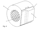
- a translational movement of the locking element 9 along the hinge pin 15 rubs the pressure element 8 on the friction surface 10 which follows a Stiction which sets the end of a pivoting movement locks the door (cf. Fig. 4 ).
- the pressure element 8 is biased to secure the function and to generate a static and sliding friction in the direction of the locking element 9.
- the pressure body 8 is formed integrally with a pressure element carrier 12, which is loaded on its side facing away from the pressure element 8 by a plate spring package 13.
- the cup spring package 13 is in turn supported with its end opposite the pressure element 8 on a closure element 14, which in a second receptacle 18 of the column console 3 can be screwed.
- the pressure element 8, the pressure element carrier 12 and the cup spring assembly 13 are also arranged displaceably.
- this case has a in the direction of the plate spring packet 13 extending pin 29, which allows a coaxial arrangement of the plate spring package 13.
- the contour of the surface of the pressure element 8 which is in contact with the friction surface 10 is adapted to the two-stage contour of the friction surface 10, so that a comfortable transition between the two regions of the friction surface 10 is possible, which have a different distance from the hinge pin 11 (cf. , Fig. 3 ).
- a first receptacle 17 for the hinge pin 15 and the locking element 9 arranged thereon is arranged in the column console 3.
- the adjustability of the locking element 9 is limited to a longitudinal displacement along the hinge pin 15. A rotational movement of the locking element 9 is prevented by the interaction of the pressure element 8, which bears transversely to the longitudinal axis of the hinge pin 15 extending on the friction surface 10.
- the hinge pin 15 To convert the rotational movement of the hinge pin 15 in a translational movement of the locking element 9, the hinge pin 15 in the connecting region with the locking element 9 on its cylindrical surface a plurality of helically around the peripheral surface extending threaded body 16.
- the locking element 9 in turn, has a passage opening 30 designed in accordance with this connection region, which allows a coaxial arrangement of the locking element 9 on the hinge pin 15, recesses 31 being arranged in the inner wall of the passage opening 30, which are adapted to the threaded bodies 16.
- the hinge pin 15 is rotated due to its rotationally fixed connection with the door bracket 2 in the receptacle 17.
- the rotationally secure arrangement of the locking element 9 in the first receptacle 17 has the consequence that by the self-adjusting "screwing" the threaded body 16 of the hinge pin 15, the locking element 9 along the hinge pin 15 and thereby relative to the locking body 8 is moved.
- the locking element 9 When pivoting the door panel 2, the locking element 9 thereby shifts relative to the pressure element carrier 12, wherein the pressure element 8 rubs on the friction surface 10 and the static friction locks the door in any opening positions.
- the position of the hinge pin 15 on the column console 3, or in the receptacle 17 is defined on the one hand by a resting on an edge of the receptacle 17 flange 22 and on the other hand by a one end of the hinge pin 15 encompassing lock washer 19.
- the flange 22 adjoins a shoulder 24, which delimits the connecting portion of the hinge pin 15 with the locking element 9 from the connection area with the door bracket 2.
- For play-free arrangement of the hinge pin 15 in the receptacle 17 of the shoulder 24 is disposed within the receptacle 17.
- the flange 22 of the hinge pin 15 on its side facing a boom 6 of the door 2 console side two diametrically arranged to a central pin 27, in the direction of the boom 6 tapered webs 23, which is arranged in the mounted state in a correspondingly formed recess 21 on a hinged pin 15 facing the bottom of the boom 6.
- the tapered design of the webs 23 ensures a play-free arrangement of the hinge pin 15 on the boom. 6
- FIG. 5 Another embodiment of a door hinge 1a is in Fig. 5 shown. This is different from the one in Fig. 1 to 4 illustrated door hinge 1 by the configuration of the print element carrier 12a and the receptacle 18a.
- the pressure element carrier 12a has a projection 25 and the receptacle 18a has a stop 34 arranged in a corresponding manner.
- the friction surface 10 is arranged at a distance from the pressure element 8 and only at the remote distance from the hinge pin 15 extending portion of the friction surface 10 with the pressure element 8 can be brought into engagement. In the area around the closed position, there is thus no interaction of the pressure element 8 with the friction surface 10, so that a simple opening of the vehicle door is possible.
- the locking element 9, 9a is formed with a formed as an elastic plastic body damping element 40, which on a flange 22 opposite end face of the first cylindrical receptacle 17th is arranged coaxially with the hinge pin 15.
- the damping element 40 By compressing the damping element 40, the movement of the door console 2 is damped in the direction of the maximum opening position.
- the damping element may be formed from a plate spring, which dampens the opening movement in an analogous manner.
Landscapes
- Engineering & Computer Science (AREA)
- Mechanical Engineering (AREA)
- Vehicle Step Arrangements And Article Storage (AREA)
Priority Applications (1)
| Application Number | Priority Date | Filing Date | Title |
|---|---|---|---|
| EP10161588A EP2256274A1 (fr) | 2010-04-30 | 2010-04-30 | Charnière de porte pour portes de véhicule automobile |
Applications Claiming Priority (1)
| Application Number | Priority Date | Filing Date | Title |
|---|---|---|---|
| EP10161588A EP2256274A1 (fr) | 2010-04-30 | 2010-04-30 | Charnière de porte pour portes de véhicule automobile |
Publications (1)
| Publication Number | Publication Date |
|---|---|
| EP2256274A1 true EP2256274A1 (fr) | 2010-12-01 |
Family
ID=42740359
Family Applications (1)
| Application Number | Title | Priority Date | Filing Date |
|---|---|---|---|
| EP10161588A Withdrawn EP2256274A1 (fr) | 2010-04-30 | 2010-04-30 | Charnière de porte pour portes de véhicule automobile |
Country Status (1)
| Country | Link |
|---|---|
| EP (1) | EP2256274A1 (fr) |
Cited By (1)
| Publication number | Priority date | Publication date | Assignee | Title |
|---|---|---|---|---|
| CN110630123A (zh) * | 2019-10-31 | 2019-12-31 | 湖南联诚轨道装备有限公司 | 一种动车组司机室活动侧窗用带阻尼铰链 |
Citations (5)
| Publication number | Priority date | Publication date | Assignee | Title |
|---|---|---|---|---|
| DE19633462A1 (de) | 1996-05-14 | 1998-02-26 | Scharwaechter Gmbh Co Kg | Mit einem aushängbaren Türscharnier baulich vereinigter Türfeststeller |
| DE19953077A1 (de) * | 1999-11-04 | 2001-05-23 | Edscha Ag | Türscharnier mit integriertem Türfeststeller, stufenlos in beliebiger Türstellung |
| DE102005008214B3 (de) * | 2005-02-22 | 2006-03-09 | Ise Innomotive Systems Europe Gmbh | Türscharnier für Kraftfahrzeuge |
| DE102006016670A1 (de) * | 2006-04-08 | 2007-10-11 | Hans-Peter Goller | Anlenkvorrichtung |
| DE102008051875A1 (de) * | 2008-08-26 | 2010-04-29 | Ise Automotive Gmbh | Türscharnier mit Feststeller |
-
2010
- 2010-04-30 EP EP10161588A patent/EP2256274A1/fr not_active Withdrawn
Patent Citations (5)
| Publication number | Priority date | Publication date | Assignee | Title |
|---|---|---|---|---|
| DE19633462A1 (de) | 1996-05-14 | 1998-02-26 | Scharwaechter Gmbh Co Kg | Mit einem aushängbaren Türscharnier baulich vereinigter Türfeststeller |
| DE19953077A1 (de) * | 1999-11-04 | 2001-05-23 | Edscha Ag | Türscharnier mit integriertem Türfeststeller, stufenlos in beliebiger Türstellung |
| DE102005008214B3 (de) * | 2005-02-22 | 2006-03-09 | Ise Innomotive Systems Europe Gmbh | Türscharnier für Kraftfahrzeuge |
| DE102006016670A1 (de) * | 2006-04-08 | 2007-10-11 | Hans-Peter Goller | Anlenkvorrichtung |
| DE102008051875A1 (de) * | 2008-08-26 | 2010-04-29 | Ise Automotive Gmbh | Türscharnier mit Feststeller |
Cited By (1)
| Publication number | Priority date | Publication date | Assignee | Title |
|---|---|---|---|---|
| CN110630123A (zh) * | 2019-10-31 | 2019-12-31 | 湖南联诚轨道装备有限公司 | 一种动车组司机室活动侧窗用带阻尼铰链 |
Similar Documents
| Publication | Publication Date | Title |
|---|---|---|
| EP2318723B1 (fr) | Agencement de fixation avec compensation des tolerances | |
| EP3973126B1 (fr) | Ferrure de meuble | |
| EP3717786B1 (fr) | Dispositif de compensation de tolérance avec sécurité par serrage | |
| EP2174571B1 (fr) | Dispositif d'ouverture pour un guidage d'extraction et mécanisme d'arrêt | |
| EP3973131B1 (fr) | Ferrure pour meuble | |
| EP2147179B1 (fr) | Amortisseur à butée | |
| EP3066282B1 (fr) | Moyen de fermeture d'une porte ou d'un ouvrant | |
| WO2016177706A1 (fr) | Charnière de meuble comprenant un amortisseur et un ressort | |
| DE19953077A1 (de) | Türscharnier mit integriertem Türfeststeller, stufenlos in beliebiger Türstellung | |
| DE102017109501A1 (de) | Verstelleinheit und Einstellverfahren für ein Bauteil | |
| EP3621483B1 (fr) | Dispositif de retenue pour façade de tiroir | |
| WO2011057966A1 (fr) | Charnière de porte pour véhicules automobiles | |
| EP2320100B1 (fr) | Barre de traction-compression | |
| EP4012200B1 (fr) | Boulon d'encliquetage sollicité par ressort | |
| EP1882798B1 (fr) | Ferrure pour porte ou fenêtre | |
| DE102004034247B3 (de) | Türscharnier für Kraftfahrzeuge | |
| AT523901B1 (de) | Selbstsichernder Vorspannring für Federbeine | |
| DE102008051875B4 (de) | Türscharnier mit Feststeller | |
| EP0931897A1 (fr) | Charnière à arrêt de porte intégré | |
| DE102014103558B3 (de) | Selbstschließendes Rollentürband | |
| EP1951977A1 (fr) | Bloc-porte mécanique pour portes, notamment pour portières de véhicule | |
| EP1501994A1 (fr) | Paumelle pour fenetres, portes ou analogues | |
| DE102020105409A1 (de) | Getriebegehäuseeinheit mit Polymerelement für axialen Spielausgleich | |
| EP4323659B1 (fr) | Palier lisse axial-radial | |
| EP2893110B1 (fr) | Ensemble butée pour un élément pouvant changer de position, monté sur une carrosserie de véhicule |
Legal Events
| Date | Code | Title | Description |
|---|---|---|---|
| PUAI | Public reference made under article 153(3) epc to a published international application that has entered the european phase |
Free format text: ORIGINAL CODE: 0009012 |
|
| AK | Designated contracting states |
Kind code of ref document: A1 Designated state(s): AT BE BG CH CY CZ DE DK EE ES FI FR GB GR HR HU IE IS IT LI LT LU LV MC MK MT NL NO PL PT RO SE SI SK SM TR |
|
| AX | Request for extension of the european patent |
Extension state: AL BA ME RS |
|
| 17P | Request for examination filed |
Effective date: 20110506 |
|
| 17Q | First examination report despatched |
Effective date: 20120326 |
|
| STAA | Information on the status of an ep patent application or granted ep patent |
Free format text: STATUS: THE APPLICATION IS DEEMED TO BE WITHDRAWN |
|
| 18D | Application deemed to be withdrawn |
Effective date: 20120807 |