EP2256281B1 - Luftführung - Google Patents
Luftführung Download PDFInfo
- Publication number
- EP2256281B1 EP2256281B1 EP10397508.2A EP10397508A EP2256281B1 EP 2256281 B1 EP2256281 B1 EP 2256281B1 EP 10397508 A EP10397508 A EP 10397508A EP 2256281 B1 EP2256281 B1 EP 2256281B1
- Authority
- EP
- European Patent Office
- Prior art keywords
- air
- window
- wall
- interspace
- flow
- Prior art date
- Legal status (The legal status is an assumption and is not a legal conclusion. Google has not performed a legal analysis and makes no representation as to the accuracy of the status listed.)
- Active
Links
- 238000009423 ventilation Methods 0.000 description 13
- 238000005452 bending Methods 0.000 description 10
- 230000001681 protective effect Effects 0.000 description 4
- 238000004519 manufacturing process Methods 0.000 description 3
- 239000002184 metal Substances 0.000 description 3
- 238000007789 sealing Methods 0.000 description 3
- 238000010792 warming Methods 0.000 description 3
- 230000000694 effects Effects 0.000 description 2
- 239000012535 impurity Substances 0.000 description 2
- 239000011248 coating agent Substances 0.000 description 1
- 238000000576 coating method Methods 0.000 description 1
- 238000005520 cutting process Methods 0.000 description 1
- 238000005553 drilling Methods 0.000 description 1
- 239000000428 dust Substances 0.000 description 1
- 238000001914 filtration Methods 0.000 description 1
- 238000000034 method Methods 0.000 description 1
- 238000003801 milling Methods 0.000 description 1
- 239000002245 particle Substances 0.000 description 1
- 229920001296 polysiloxane Polymers 0.000 description 1
- 229920002635 polyurethane Polymers 0.000 description 1
- 239000004814 polyurethane Substances 0.000 description 1
- 238000004080 punching Methods 0.000 description 1
- 239000007787 solid Substances 0.000 description 1
- XLYOFNOQVPJJNP-UHFFFAOYSA-N water Substances O XLYOFNOQVPJJNP-UHFFFAOYSA-N 0.000 description 1
Images


Classifications
-
- E—FIXED CONSTRUCTIONS
- E06—DOORS, WINDOWS, SHUTTERS, OR ROLLER BLINDS IN GENERAL; LADDERS
- E06B—FIXED OR MOVABLE CLOSURES FOR OPENINGS IN BUILDINGS, VEHICLES, FENCES OR LIKE ENCLOSURES IN GENERAL, e.g. DOORS, WINDOWS, BLINDS, GATES
- E06B7/00—Special arrangements or measures in connection with doors or windows
- E06B7/02—Special arrangements or measures in connection with doors or windows for providing ventilation, e.g. through double windows; Arrangement of ventilation roses
-
- E—FIXED CONSTRUCTIONS
- E06—DOORS, WINDOWS, SHUTTERS, OR ROLLER BLINDS IN GENERAL; LADDERS
- E06B—FIXED OR MOVABLE CLOSURES FOR OPENINGS IN BUILDINGS, VEHICLES, FENCES OR LIKE ENCLOSURES IN GENERAL, e.g. DOORS, WINDOWS, BLINDS, GATES
- E06B7/00—Special arrangements or measures in connection with doors or windows
- E06B7/02—Special arrangements or measures in connection with doors or windows for providing ventilation, e.g. through double windows; Arrangement of ventilation roses
- E06B2007/026—Special arrangements or measures in connection with doors or windows for providing ventilation, e.g. through double windows; Arrangement of ventilation roses with air flow between panes
-
- E—FIXED CONSTRUCTIONS
- E06—DOORS, WINDOWS, SHUTTERS, OR ROLLER BLINDS IN GENERAL; LADDERS
- E06B—FIXED OR MOVABLE CLOSURES FOR OPENINGS IN BUILDINGS, VEHICLES, FENCES OR LIKE ENCLOSURES IN GENERAL, e.g. DOORS, WINDOWS, BLINDS, GATES
- E06B7/00—Special arrangements or measures in connection with doors or windows
- E06B7/16—Sealing arrangements on wings or parts co-operating with the wings
- E06B7/22—Sealing arrangements on wings or parts co-operating with the wings by means of elastic edgings, e.g. elastic rubber tubes; by means of resilient edgings, e.g. felt or plush strips, resilient metal strips
Definitions
- the present invention relates to an air guide according to the appended claim 1 as well as a window according to the appended claim 3.
- the exhaust air ventilation system comprises a mechanical vent device which removes air mechanically from a room and causes an underpressure in the room.
- the supply air/exhaust air system also comprises a mechanical vent arrangement for removing spent air from a room, and an inlet air duct system, through which replacement air is introduced into the room.
- both the gravitational system and the exhaust air ventilation system apply a replacement air valve, via which replacement air is introduced into the room.
- a replacement air valve is typically provided in connection with a window, for example in the built-in frame above the window or in the casement frame.
- a window normally comprises two or more panes, wherein said interspace is formed in the space left between two panes in the window.
- the window comprises three panes
- the window thus comprises two interspaces, of which the first one is between the outermost pane (the pane on the outdoor side) and the middle pane, and the second one is between the middle pane and the innermost pane (the pane on the indoor side), respectively.
- the replacement air can be introduced into either the first interspace or the second interspace or even both, for example first into the first interspace and from there into the second interspace.
- the ventilation element comprises cylindrical, tapered air channels for leading replacement air into a room.
- the air channels have balls which are able to rotate in the air channels. If the speed of the air flow in the air channels increases e.g. due to a strong wind, the balls rotate towards the narrower end of the air channels wherein they reduce, if not totally suspend, air flowing into the room. In other words, the balls are adapted to operate as air flow restricting elements.
- the ventilation device also comprises an air guide installed on the surface of the casement of the window.
- the air guide has a louver via which the replacement air can flow into the room, and a wall which turns the air flow downwards.
- the air guide has a protrusion which can be used to attach the air guide to the ventilation device above the casement of the window.
- the first inlet conveys the replacement air from the outside into the interspace of the window
- the second inlet conveys the air warmed in the interspace of the window further via the replacement air valve into the room.
- the first inlet is normally provided either in the casement or, for example, in the lower profile of the built-in frame of the window. Providing such an inlet requires drilling, milling and/or other work stages, so that an air flow duct is formed from outdoor air into the window interspace.
- DE2404836 discloses a frame, especially for double-glazed windows.
- the frame comprises metal frame beams formed from bevelled or corresponding profiled metal strip.
- a hard ash layer such as polyurethane or the like, wherein in the coating area of the thermally conductive cross-section of the metal strips is kept to a minimum through holes or through complete transection.
- the air guide according to the present invention is primarily characterized in what will be presented in the characterizing part of the appended claim 1.
- the window according to the present invention is primarily characterized in what will be presented in the characterizing part of the appended claim 3.
- the present invention shows remarkable advantages over solutions of prior art.
- the air guide according to the invention is applied, there is no need to provide the window with a separate inlet for introducing replacement air from the outside into the window interspace, but this can be implemented by means of a gap left between the casement and the built-in frame of the window.
- the air guide and this gap together form a first inlet for introducing replacement air from outdoors to the window interspace in such a way that the replacement air from outdoors tends to flow downwards in the window interspace, until the replacement air becomes warmer and starts to flow upwards in the window interspace towards a second inlet, from which the replacement air is conveyed to the duct system of a replacement air valve and further into a room.
- the supply of replacement air can be implemented by fewer work stages than by using solutions of prior art.
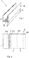
- the air guide 1 comprises a first wall 2 which is used for fastening the air guide in connection with a window 3 ( Fig. 3 ) in a way to be presented below.
- the air guide 1 further comprises a second wall 4 and a flow louver 5 which form a first inlet 6 for introducing air into a window interspace 10a, 10b.
- the flow louver 5 is formed, for example, by punching or providing openings in another way in that part of the air guide 1 which is between the first wall 2 and the second wall 4.
- the openings can be made in the sheet preform 21, for example, by die cutting. An example of such a sheet preform 21 and the manufacture of an air guide from the sheet preform 21 will be described below in this description.
- the air guide 1 further comprises a guide wall 8 for the air flow, tending to guide the air flowing through the flow louver 5 towards the surface of the outer pane 9a of the window and further downwards in the window interspace.
- a guide wall 8 for the air flow can be formed as a solid wall with said second wall 4.
- the flow louver 5 can be provided with one or more filters 24 for filtering out impurities, such as dust particles etc., possibly entrained in the replacement air. In this way, at least part of the impurities are trapped in the filter and do not find their way into the room.
- Figure 3 shows an embodiment of a window 3 provided with an air guide 1 according to the invention.
- the window 3 comprises three panes 9a, 9b, 9c, wherein a first interspace 10a is formed between the first pane 9a and the second pane 9b, and a second interspace 10b is formed between the second pane 9b and the third pane 9c, respectively.
- the window 3 also comprises a first casement 11a and a second casement 11b, but it is obvious that the number of casements 11a, 11b may also be only one or greater than two.
- the casements 11a, 11b are preferably formed to encircle the panes 9a, 9b, 9c at each edge; in other words, the casements 11a, 11b preferably comprise four casement elements, one at each edge of the pane.
- Each pane 9a, 9b, 9c is partly embedded in the respective casement 11a, 11b and, if necessary, the joint between the casement 11a, 11b and the pane can be sealed with, for example, silicone.
- the window 3 comprises a built-in frame 12, to which the casements 11a, 11b can be attached, for example, by hinges (not shown).
- the built-in frame 12 is also arranged to encircle the casements of the window, wherein the frame preferably consists of four frame elements.
- the window 3 can be fixed to the wall 13 of a room by any suitable fastening means (not shown). Between the frame 12 and the wall 13, a small gap is typically left, whose size is in the order of a few millimetres.
- This gap such as, for example, the gap formed between the frame element above the window and the wall 13, can be used to accommodate, for example, a replacement air valve 14 to introduce replacement air into the room.
- this gap 15 is utilized by fastening an air guide 1 preferably to the first casement 11a of the window in such a way that the air guide 1 is in the first interspace 10a and that the first inlet 6 of the air guide 1 is in a flow connection with this gap 15.
- an air guide 1 preferably to the first casement 11a of the window in such a way that the air guide 1 is in the first interspace 10a and that the first inlet 6 of the air guide 1 is in a flow connection with this gap 15.
- the air flow guide wall 8 of the air guide guides the flow of replacement air towards the inner surface of the outermost pane 9a of the first interspace 10a.
- This flow is illustrated by arrow F1 in Fig. 3 .
- the replacement air flows downwards; in other words, it, in a way, runs on the inner surface of the first pane 9a. From the room, warm air is emitted and conducted through the panes into the interspace, wherein replacement air from outdoors also becomes slightly warmer when it flows downwards. At least partly for this reason, the air flow starts to turn upwards towards the upper end of the first interspace 10a.
- an air flow duct 16 is provided in the built-in frame to let the replacement air that has become warmer in the first interspace 10a flow into the replacement air valve 14. This flow is illustrated by an arrow F2 in Fig. 3 .
- the upper edge of the second wall 4 of the air guide 1 can further be provided with a sealing 20 to prevent the flow of replacement air from between the second wall 4 and the built-in frame 12 directly into the air flow duct 16. Such a by-pass flow might diminish the effect of warming the replacement air.
- the replacement air valve 14 has two positions which may be called, for example, the summer position and the winter position.
- the summer position the above-mentioned air flow duct 16 is closed, preventing the flow of replacement air through the window interspace into the replacement air valve. This is advantageous, among other things, for the reason that in a situation in which outdoor air is warmer than the target temperature of indoor air, the warming effect of the window interspace is not desirable.
- the summer position the replacement air is guided to pass directly from the inlet 17 to the duct system of the replacement air valve and further into the room.
- the window 3 can also be provided with a protective plate 18 which, particularly above the window, reduces the entry of rain water through the gap 15 between the first casement 11a, that is, the casement of the outermost pane, and the built-in frame into the interspace 10a. A small clearance is left between this protective plate and the first casement 11a along at least part of the length of the first casement 11a, to enable the flow of replacement air into the first interspace 10a.
- this protective plate 18 also extends to the built-in frame advantageously so that an air gap 19 is also left between the protective plate 18 and the built-in frame 12, allowing replacement air to flow into the inlet 17 of the replacement air valve 14, when the replacement air valve 14 is in the summer position. This flow is illustrated by an arrow F3 in Fig. 3 .
- Figure 4 shows an advantageous example of a sheet preform 21, of which the air guide 1 according to the invention can be made.
- the sheet preform 21 is shaped so that by bending it at the locations marked with broken lines, the desired shape of the air guide 1 can be achieved.
- four such bending lines 22a-22d are shown.
- the area between the first bending line 22a and the second bending line 22b is provided with a set of openings, wherein this part of the sheet preform constitutes the flow louver 5 of the air guide 1.
- the sheet preform 21 can also be bent at the third bending line 22c to form the air flow guide wall 8.
- This air flow guide wall 8 can be provided with yet another deflection at the location indicated by the fourth bending line 22d.
- the air guide 1 can also be made of two or more parts, for example in such a way that the air flow guide wall 8 is a separate sheet that is attached to the second wall 2 by means of a suitable fastening method.
- the sheet preform can be thought to be cut at the third bending line into two separate parts, wherein one part forms the first wall 2, the second wall 4 and the flow louver 5, and the other part forms the air flow guide wall 8.
- At least one of the bending angles corresponding to the first bending line 22a and second bending line 22b is a few degrees greater than 90 degrees while the other is in the order of 90 degrees, wherein the distance between the first wall 2 and the second wall 4 reduces slightly when moving away from the flow louver.
- the air guide 1 according to the invention can be fastened to the first casement 11a of the window by means of, for example, double sided tape, magnetic tape 23 that is, for example, glued to the first wall 2 of the air guide as shown in Fig. 2 , sticker tape, or the like.
- the first interspace 10a and the second interspace 10b of the window 3 can be arranged in a flow connection with each other advantageously in the vicinity of the lower edge of the window, wherein the replacement air flowing into the first interspace 10a can move into the second interspace 10b of the window.
- the air flow duct 16 of the replacement air valve 14 is placed advantageously in the second built-in frame.
- the replacement air entering the lower part of the second interspace 10b can flow upwards in this second interspace 10b and further through the air flow duct 16 into the replacement air valve 14.
- the air guide 1 according to the invention can also be used, for example, in connection with a door arrangement for a balcony or a terrace.
- a door arrangement preferably comprises two doors, wherein a relatively tight interspace is left between these two doors (not shown) when both of the doors are closed.
- the air guide 1 according to the invention is fastened at the upper edge of the outermost door, where at least part of the sealing is removed, if necessary, to enable the flow of replacement air from outdoor air via the air guide into the interspace between the doors.
- a replacement air valve can be provided at the upper edge of the inner door or in its upper built-in frame, through which valve the replacement air that has entered the interspace can be led into the room.
Landscapes
- Engineering & Computer Science (AREA)
- Civil Engineering (AREA)
- Structural Engineering (AREA)
- Specific Sealing Or Ventilating Devices For Doors And Windows (AREA)
Claims (3)
- Luftführung (1) für ein Fenster (3), wobei das Fenster mindestens einen ersten Flügel (11a) umfasst, an dem eine erste Scheibe (9a) befestigt ist, und einen zweiten Flügel (11b), an dem eine zweite Scheibe (9b) befestigt ist, wobei ein Zwischenraum (10a) zwischen der ersten Scheibe (9a) und der zweiten Scheibe (9b) vorgesehen ist, wobei die Luftführung (1) eine erste Wand (2), eine zweite Wand (4), einen Strömungsschlitz (5) zwischen der ersten Wand (2) und der zweiten Wand (4) und eine Luftströmungsführungswand (8) zum Führen der Ersatzluft in den ersten Zwischenraum (10a) des Fensters umfasst, wobei die erste Wand (2), die zweite Wand (4) und der Strömungsschlitz (5) einen ersten Einlass (6) zum Fördern von Ersatzluft in die Luftführung (1) bilden, wobei die Luftführung (1) Mittel (23) zum Befestigen der Luftführung an dem ersten Flügel (11a) des Fensters (3) umfasst, dadurch gekennzeichnet, dass sich der Abstand zwischen der ersten Wand (2) und der zweiten Wand (4) beim Wegbewegen von de Strömungsschlitz (5) geringfügig verringert, und dass ein Filter (24) von der ersten Wand (2) und der zweiten Wand (4) zwischen ihnen getragen wird.
- Luftführung (1) nach Anspruch 1, dadurch gekennzeichnet, dass das Mittel (23) zum Befestigen der Luftführung angeordnet ist, um an dem ersten Flügel (11a) des Fensters (3) durch mindestens eines der folgenden befestigt zu werden:- doppelseitiges Klebeband;- Magnetband.
- Fenster (3), das mindestens einen ersten Flügel (11a) umfasst, an dem eine erste Scheibe (9a) befestigt ist, und einen zweiten Flügel (11b), an dem eine zweite Scheibe (9b) befestigt ist, und einen eingebauten Rahmen (12), mit dem der erste Flügel (11a) und der zweite Flügel (11b) zum Befestigen angepasst sind, wobei ein Zwischenraum (10a) zwischen der ersten Scheibe (9a) und der zweiten Scheibe (9b) vorgesehen ist und ein Spalt (15) zwischen dem ersten Flügel (11a) und dem eingebauten Rahmen (12) vorgesehen ist, dadurch gekennzeichnet, dass das Fenster (1) ferner eine Luftführung (1) gemäß einem der Ansprüche 1 bis 2 in dem Zwischenraum (10a) umfasst, wobei der erste Einlass (6) angepasst ist, um Ersatzluft über den Spalt (15) aufzunehmen.
Applications Claiming Priority (1)
| Application Number | Priority Date | Filing Date | Title |
|---|---|---|---|
| FI20090210U FI8437U1 (fi) | 2009-05-29 | 2009-05-29 | Ilmanohjain |
Publications (3)
| Publication Number | Publication Date |
|---|---|
| EP2256281A2 EP2256281A2 (de) | 2010-12-01 |
| EP2256281A3 EP2256281A3 (de) | 2014-01-01 |
| EP2256281B1 true EP2256281B1 (de) | 2021-03-31 |
Family
ID=40680814
Family Applications (1)
| Application Number | Title | Priority Date | Filing Date |
|---|---|---|---|
| EP10397508.2A Active EP2256281B1 (de) | 2009-05-29 | 2010-05-24 | Luftführung |
Country Status (2)
| Country | Link |
|---|---|
| EP (1) | EP2256281B1 (de) |
| FI (1) | FI8437U1 (de) |
Families Citing this family (4)
| Publication number | Priority date | Publication date | Assignee | Title |
|---|---|---|---|---|
| JP6175246B2 (ja) * | 2012-02-29 | 2017-08-02 | 三協立山株式会社 | 二重窓 |
| FR3009332B1 (fr) * | 2013-08-02 | 2021-04-23 | Asselin | Menuiserie portant un vitrail et un vitrage isolant avec une lame d'air entre eux, permettant la mise en communication de la lame d'air avec l'air libre exterieur |
| CN113384125B (zh) * | 2021-07-08 | 2023-01-17 | 陈艳 | 一种防风型且强度高的智能安防窗帘 |
| FR3127508B1 (fr) * | 2021-09-27 | 2023-08-25 | Akerib Andre | Dispositif de panneau vitré et procédé d'implantation associé |
Citations (1)
| Publication number | Priority date | Publication date | Assignee | Title |
|---|---|---|---|---|
| DE2404836A1 (de) * | 1974-02-01 | 1975-08-07 | Hans Viessmann | Zarge, insbesondere fuer doppelfenster |
Family Cites Families (3)
| Publication number | Priority date | Publication date | Assignee | Title |
|---|---|---|---|---|
| NZ236161A (en) * | 1990-11-20 | 1995-04-27 | Altherm Aluminium Nz Ltd | Controllable ventilation rail with channel for window sashes |
| DE29719751U1 (de) * | 1997-11-07 | 1998-01-02 | Pohl, Benedikt, 26871 Papenburg | Belüftungseinrichtung für Fensterelemente |
| EP1809848B1 (de) * | 2004-10-21 | 2011-11-30 | Christensen Horn, Irene Karoline | Lüftungsvorrichtung |
-
2009
- 2009-05-29 FI FI20090210U patent/FI8437U1/fi not_active IP Right Cessation
-
2010
- 2010-05-24 EP EP10397508.2A patent/EP2256281B1/de active Active
Patent Citations (1)
| Publication number | Priority date | Publication date | Assignee | Title |
|---|---|---|---|---|
| DE2404836A1 (de) * | 1974-02-01 | 1975-08-07 | Hans Viessmann | Zarge, insbesondere fuer doppelfenster |
Also Published As
| Publication number | Publication date |
|---|---|
| FIU20090210U0 (fi) | 2009-05-29 |
| FI8437U1 (fi) | 2009-09-15 |
| EP2256281A3 (de) | 2014-01-01 |
| EP2256281A2 (de) | 2010-12-01 |
Similar Documents
| Publication | Publication Date | Title |
|---|---|---|
| EP1970525B1 (de) | Glasfassadenelement | |
| JP6175246B2 (ja) | 二重窓 | |
| US4577619A (en) | Energy efficient window and skylight assemblies | |
| EP3845718B1 (de) | Dachfenstersystem mit einer neben dem dachfenster montierten lüftungseinheit und verfahren zur belüftung eines gebäudes | |
| US10526836B2 (en) | Adhesive-attached window glazing assembly, multi-glazed window assembly and method therefor | |
| EP2256281B1 (de) | Luftführung | |
| US20230279664A1 (en) | Roof window system with a ventilation unit mounted adjacent to the roof window, a roof structure including a roof window system, a method of providing a roof window system and a method of retrofitting a roof window system | |
| NL2006400C2 (nl) | Gebouw met verbeterd ventilatiesysteem alsmede ventilatie-inrichting daarvoor. | |
| CN101812957B (zh) | 隔音通风窗 | |
| CH713357A2 (de) | Isolierglas mit Belüftungseinrichtung. | |
| CN105134010A (zh) | 一种标准化一体式中空遮阳玻璃窗 | |
| EP0951630B1 (de) | Raumbelüftungsverfahren und vorrichtung zur durchführung des verfahrens | |
| KR100662657B1 (ko) | 미세 조절이 가능한 환기 창문 | |
| EP4350097A1 (de) | Dynamische isolationswandanordnung und zugehöriges steuerungsverfahren | |
| KR102197170B1 (ko) | 실외기-외부 창 구조물 연결조립체 | |
| KR100662656B1 (ko) | 창유리 부위를 이용한 환기 창문 | |
| CN108005317A (zh) | 一种活动的屋顶结构 | |
| FI126713B (en) | Ventilation element for window and window | |
| PL226109B1 (pl) | Swietlik dachowy z nawiewnikiem swiezego powietrza | |
| DE102005017264A1 (de) | Innenvorsatzfenster mit Zwangslüftungselement | |
| FI12468U1 (fi) | Tuloilmajärjestely | |
| SE530207C2 (sv) | Envägsventil och fönster med medel för värmeåtervinning | |
| CN202348027U (zh) | 一种窗扇结构 | |
| DD240233A1 (de) | Hinterlueftete fenster-aussenwandkonstruktion zur energiesparenden raumlueftung | |
| JP2020172844A (ja) | 二重窓の製造方法 |
Legal Events
| Date | Code | Title | Description |
|---|---|---|---|
| PUAI | Public reference made under article 153(3) epc to a published international application that has entered the european phase |
Free format text: ORIGINAL CODE: 0009012 |
|
| AK | Designated contracting states |
Kind code of ref document: A2 Designated state(s): AL AT BE BG CH CY CZ DE DK EE ES FI FR GB GR HR HU IE IS IT LI LT LU LV MC MK MT NL NO PL PT RO SE SI SK SM TR |
|
| AX | Request for extension of the european patent |
Extension state: BA ME RS |
|
| PUAL | Search report despatched |
Free format text: ORIGINAL CODE: 0009013 |
|
| AK | Designated contracting states |
Kind code of ref document: A3 Designated state(s): AL AT BE BG CH CY CZ DE DK EE ES FI FR GB GR HR HU IE IS IT LI LT LU LV MC MK MT NL NO PL PT RO SE SI SK SM TR |
|
| AX | Request for extension of the european patent |
Extension state: BA ME RS |
|
| RIC1 | Information provided on ipc code assigned before grant |
Ipc: E06B 7/02 20060101AFI20131126BHEP |
|
| 17P | Request for examination filed |
Effective date: 20140613 |
|
| RBV | Designated contracting states (corrected) |
Designated state(s): AL AT BE BG CH CY CZ DE DK EE ES FI FR GB GR HR HU IE IS IT LI LT LU LV MC MK MT NL NO PL PT RO SE SI SK SM TR |
|
| RAP1 | Party data changed (applicant data changed or rights of an application transferred) |
Owner name: AIR TERMICO OY |
|
| STAA | Information on the status of an ep patent application or granted ep patent |
Free format text: STATUS: EXAMINATION IS IN PROGRESS |
|
| 17Q | First examination report despatched |
Effective date: 20170123 |
|
| RAP1 | Party data changed (applicant data changed or rights of an application transferred) |
Owner name: AIR TERMICO OY |
|
| GRAP | Despatch of communication of intention to grant a patent |
Free format text: ORIGINAL CODE: EPIDOSNIGR1 |
|
| STAA | Information on the status of an ep patent application or granted ep patent |
Free format text: STATUS: GRANT OF PATENT IS INTENDED |
|
| INTG | Intention to grant announced |
Effective date: 20201022 |
|
| RIN1 | Information on inventor provided before grant (corrected) |
Inventor name: TARPIO, TAPIO |
|
| GRAS | Grant fee paid |
Free format text: ORIGINAL CODE: EPIDOSNIGR3 |
|
| GRAA | (expected) grant |
Free format text: ORIGINAL CODE: 0009210 |
|
| STAA | Information on the status of an ep patent application or granted ep patent |
Free format text: STATUS: THE PATENT HAS BEEN GRANTED |
|
| AK | Designated contracting states |
Kind code of ref document: B1 Designated state(s): AL AT BE BG CH CY CZ DE DK EE ES FI FR GB GR HR HU IE IS IT LI LT LU LV MC MK MT NL NO PL PT RO SE SI SK SM TR |
|
| REG | Reference to a national code |
Ref country code: GB Ref legal event code: FG4D Ref country code: CH Ref legal event code: EP |
|
| REG | Reference to a national code |
Ref country code: DE Ref legal event code: R096 Ref document number: 602010066675 Country of ref document: DE Ref country code: AT Ref legal event code: REF Ref document number: 1377100 Country of ref document: AT Kind code of ref document: T Effective date: 20210415 |
|
| REG | Reference to a national code |
Ref country code: IE Ref legal event code: FG4D |
|
| REG | Reference to a national code |
Ref country code: FI Ref legal event code: FGE |
|
| REG | Reference to a national code |
Ref country code: SE Ref legal event code: TRGR |
|
| REG | Reference to a national code |
Ref country code: LT Ref legal event code: MG9D |
|
| PG25 | Lapsed in a contracting state [announced via postgrant information from national office to epo] |
Ref country code: HR Free format text: LAPSE BECAUSE OF FAILURE TO SUBMIT A TRANSLATION OF THE DESCRIPTION OR TO PAY THE FEE WITHIN THE PRESCRIBED TIME-LIMIT Effective date: 20210331 Ref country code: NO Free format text: LAPSE BECAUSE OF FAILURE TO SUBMIT A TRANSLATION OF THE DESCRIPTION OR TO PAY THE FEE WITHIN THE PRESCRIBED TIME-LIMIT Effective date: 20210630 Ref country code: BG Free format text: LAPSE BECAUSE OF FAILURE TO SUBMIT A TRANSLATION OF THE DESCRIPTION OR TO PAY THE FEE WITHIN THE PRESCRIBED TIME-LIMIT Effective date: 20210630 |
|
| PG25 | Lapsed in a contracting state [announced via postgrant information from national office to epo] |
Ref country code: LV Free format text: LAPSE BECAUSE OF FAILURE TO SUBMIT A TRANSLATION OF THE DESCRIPTION OR TO PAY THE FEE WITHIN THE PRESCRIBED TIME-LIMIT Effective date: 20210331 |
|
| REG | Reference to a national code |
Ref country code: NL Ref legal event code: MP Effective date: 20210331 |
|
| REG | Reference to a national code |
Ref country code: AT Ref legal event code: MK05 Ref document number: 1377100 Country of ref document: AT Kind code of ref document: T Effective date: 20210331 |
|
| PG25 | Lapsed in a contracting state [announced via postgrant information from national office to epo] |
Ref country code: AT Free format text: LAPSE BECAUSE OF FAILURE TO SUBMIT A TRANSLATION OF THE DESCRIPTION OR TO PAY THE FEE WITHIN THE PRESCRIBED TIME-LIMIT Effective date: 20210331 Ref country code: SM Free format text: LAPSE BECAUSE OF FAILURE TO SUBMIT A TRANSLATION OF THE DESCRIPTION OR TO PAY THE FEE WITHIN THE PRESCRIBED TIME-LIMIT Effective date: 20210331 Ref country code: NL Free format text: LAPSE BECAUSE OF FAILURE TO SUBMIT A TRANSLATION OF THE DESCRIPTION OR TO PAY THE FEE WITHIN THE PRESCRIBED TIME-LIMIT Effective date: 20210331 Ref country code: LT Free format text: LAPSE BECAUSE OF FAILURE TO SUBMIT A TRANSLATION OF THE DESCRIPTION OR TO PAY THE FEE WITHIN THE PRESCRIBED TIME-LIMIT Effective date: 20210331 Ref country code: CZ Free format text: LAPSE BECAUSE OF FAILURE TO SUBMIT A TRANSLATION OF THE DESCRIPTION OR TO PAY THE FEE WITHIN THE PRESCRIBED TIME-LIMIT Effective date: 20210331 Ref country code: EE Free format text: LAPSE BECAUSE OF FAILURE TO SUBMIT A TRANSLATION OF THE DESCRIPTION OR TO PAY THE FEE WITHIN THE PRESCRIBED TIME-LIMIT Effective date: 20210331 |
|
| PG25 | Lapsed in a contracting state [announced via postgrant information from national office to epo] |
Ref country code: RO Free format text: LAPSE BECAUSE OF FAILURE TO SUBMIT A TRANSLATION OF THE DESCRIPTION OR TO PAY THE FEE WITHIN THE PRESCRIBED TIME-LIMIT Effective date: 20210331 Ref country code: IS Free format text: LAPSE BECAUSE OF FAILURE TO SUBMIT A TRANSLATION OF THE DESCRIPTION OR TO PAY THE FEE WITHIN THE PRESCRIBED TIME-LIMIT Effective date: 20210731 Ref country code: PT Free format text: LAPSE BECAUSE OF FAILURE TO SUBMIT A TRANSLATION OF THE DESCRIPTION OR TO PAY THE FEE WITHIN THE PRESCRIBED TIME-LIMIT Effective date: 20210802 Ref country code: PL Free format text: LAPSE BECAUSE OF FAILURE TO SUBMIT A TRANSLATION OF THE DESCRIPTION OR TO PAY THE FEE WITHIN THE PRESCRIBED TIME-LIMIT Effective date: 20210331 Ref country code: SK Free format text: LAPSE BECAUSE OF FAILURE TO SUBMIT A TRANSLATION OF THE DESCRIPTION OR TO PAY THE FEE WITHIN THE PRESCRIBED TIME-LIMIT Effective date: 20210331 Ref country code: ES Free format text: LAPSE BECAUSE OF FAILURE TO SUBMIT A TRANSLATION OF THE DESCRIPTION OR TO PAY THE FEE WITHIN THE PRESCRIBED TIME-LIMIT Effective date: 20210331 |
|
| REG | Reference to a national code |
Ref country code: DE Ref legal event code: R119 Ref document number: 602010066675 Country of ref document: DE |
|
| REG | Reference to a national code |
Ref country code: CH Ref legal event code: PL |
|
| PG25 | Lapsed in a contracting state [announced via postgrant information from national office to epo] |
Ref country code: DK Free format text: LAPSE BECAUSE OF FAILURE TO SUBMIT A TRANSLATION OF THE DESCRIPTION OR TO PAY THE FEE WITHIN THE PRESCRIBED TIME-LIMIT Effective date: 20210331 Ref country code: MC Free format text: LAPSE BECAUSE OF FAILURE TO SUBMIT A TRANSLATION OF THE DESCRIPTION OR TO PAY THE FEE WITHIN THE PRESCRIBED TIME-LIMIT Effective date: 20210331 Ref country code: LU Free format text: LAPSE BECAUSE OF NON-PAYMENT OF DUE FEES Effective date: 20210524 Ref country code: LI Free format text: LAPSE BECAUSE OF NON-PAYMENT OF DUE FEES Effective date: 20210531 Ref country code: CH Free format text: LAPSE BECAUSE OF NON-PAYMENT OF DUE FEES Effective date: 20210531 Ref country code: AL Free format text: LAPSE BECAUSE OF FAILURE TO SUBMIT A TRANSLATION OF THE DESCRIPTION OR TO PAY THE FEE WITHIN THE PRESCRIBED TIME-LIMIT Effective date: 20210331 |
|
| PLBE | No opposition filed within time limit |
Free format text: ORIGINAL CODE: 0009261 |
|
| STAA | Information on the status of an ep patent application or granted ep patent |
Free format text: STATUS: NO OPPOSITION FILED WITHIN TIME LIMIT |
|
| REG | Reference to a national code |
Ref country code: BE Ref legal event code: MM Effective date: 20210531 |
|
| GBPC | Gb: european patent ceased through non-payment of renewal fee |
Effective date: 20210630 |
|
| 26N | No opposition filed |
Effective date: 20220104 |
|
| PG25 | Lapsed in a contracting state [announced via postgrant information from national office to epo] |
Ref country code: IE Free format text: LAPSE BECAUSE OF NON-PAYMENT OF DUE FEES Effective date: 20210524 Ref country code: GB Free format text: LAPSE BECAUSE OF NON-PAYMENT OF DUE FEES Effective date: 20210630 Ref country code: DE Free format text: LAPSE BECAUSE OF NON-PAYMENT OF DUE FEES Effective date: 20211201 |
|
| PG25 | Lapsed in a contracting state [announced via postgrant information from national office to epo] |
Ref country code: IS Free format text: LAPSE BECAUSE OF FAILURE TO SUBMIT A TRANSLATION OF THE DESCRIPTION OR TO PAY THE FEE WITHIN THE PRESCRIBED TIME-LIMIT Effective date: 20210731 Ref country code: FR Free format text: LAPSE BECAUSE OF NON-PAYMENT OF DUE FEES Effective date: 20210531 |
|
| PG25 | Lapsed in a contracting state [announced via postgrant information from national office to epo] |
Ref country code: IT Free format text: LAPSE BECAUSE OF FAILURE TO SUBMIT A TRANSLATION OF THE DESCRIPTION OR TO PAY THE FEE WITHIN THE PRESCRIBED TIME-LIMIT Effective date: 20210331 Ref country code: BE Free format text: LAPSE BECAUSE OF NON-PAYMENT OF DUE FEES Effective date: 20210531 |
|
| PG25 | Lapsed in a contracting state [announced via postgrant information from national office to epo] |
Ref country code: HU Free format text: LAPSE BECAUSE OF FAILURE TO SUBMIT A TRANSLATION OF THE DESCRIPTION OR TO PAY THE FEE WITHIN THE PRESCRIBED TIME-LIMIT; INVALID AB INITIO Effective date: 20100524 Ref country code: CY Free format text: LAPSE BECAUSE OF FAILURE TO SUBMIT A TRANSLATION OF THE DESCRIPTION OR TO PAY THE FEE WITHIN THE PRESCRIBED TIME-LIMIT Effective date: 20210331 |
|
| PG25 | Lapsed in a contracting state [announced via postgrant information from national office to epo] |
Ref country code: GR Free format text: LAPSE BECAUSE OF FAILURE TO SUBMIT A TRANSLATION OF THE DESCRIPTION OR TO PAY THE FEE WITHIN THE PRESCRIBED TIME-LIMIT Effective date: 20210331 |
|
| PG25 | Lapsed in a contracting state [announced via postgrant information from national office to epo] |
Ref country code: MK Free format text: LAPSE BECAUSE OF FAILURE TO SUBMIT A TRANSLATION OF THE DESCRIPTION OR TO PAY THE FEE WITHIN THE PRESCRIBED TIME-LIMIT Effective date: 20210331 |
|
| PG25 | Lapsed in a contracting state [announced via postgrant information from national office to epo] |
Ref country code: TR Free format text: LAPSE BECAUSE OF FAILURE TO SUBMIT A TRANSLATION OF THE DESCRIPTION OR TO PAY THE FEE WITHIN THE PRESCRIBED TIME-LIMIT Effective date: 20210331 |
|
| PG25 | Lapsed in a contracting state [announced via postgrant information from national office to epo] |
Ref country code: MT Free format text: LAPSE BECAUSE OF FAILURE TO SUBMIT A TRANSLATION OF THE DESCRIPTION OR TO PAY THE FEE WITHIN THE PRESCRIBED TIME-LIMIT Effective date: 20210331 |
|
| PGFP | Annual fee paid to national office [announced via postgrant information from national office to epo] |
Ref country code: SE Payment date: 20250307 Year of fee payment: 16 |
|
| PGFP | Annual fee paid to national office [announced via postgrant information from national office to epo] |
Ref country code: FI Payment date: 20250305 Year of fee payment: 16 |