EP2256298A2 - Ensemble de buse de singulet de turbine avec arrêt radial et rainure - Google Patents
Ensemble de buse de singulet de turbine avec arrêt radial et rainure Download PDFInfo
- Publication number
- EP2256298A2 EP2256298A2 EP10155881A EP10155881A EP2256298A2 EP 2256298 A2 EP2256298 A2 EP 2256298A2 EP 10155881 A EP10155881 A EP 10155881A EP 10155881 A EP10155881 A EP 10155881A EP 2256298 A2 EP2256298 A2 EP 2256298A2
- Authority
- EP
- European Patent Office
- Prior art keywords
- interface
- sidewall
- nozzle assembly
- ring
- outer ring
- Prior art date
- Legal status (The legal status is an assumption and is not a legal conclusion. Google has not performed a legal analysis and makes no representation as to the accuracy of the status listed.)
- Granted
Links
Images


Classifications
-
- F—MECHANICAL ENGINEERING; LIGHTING; HEATING; WEAPONS; BLASTING
- F01—MACHINES OR ENGINES IN GENERAL; ENGINE PLANTS IN GENERAL; STEAM ENGINES
- F01D—NON-POSITIVE DISPLACEMENT MACHINES OR ENGINES, e.g. STEAM TURBINES
- F01D9/00—Stators
- F01D9/02—Nozzles; Nozzle boxes; Stator blades; Guide conduits, e.g. individual nozzles
- F01D9/04—Nozzles; Nozzle boxes; Stator blades; Guide conduits, e.g. individual nozzles forming ring or sector
Definitions
- the invention relates generally to turbine technology. More particularly, the invention relates to a turbine singlet nozzle assembly design with a radial stop and a narrow groove for weld preparation.
- Turbines including gas or steam turbines, include nozzle assemblies that direct a flow of steam or gas into rotating blades that are coupled to a rotating shaft so as to cause the rotating shaft to turn.
- One configuration for the nozzle assemblies includes a singlet design, including a blade, or airfoil, between inner and outer sidewalls, with the sidewalls coupled to an inner and outer ring, respectively, and with a mechanical axial stop at the interface between the sidewalls and the rings.
- GTAW gas tungsten arc welds
- GMAW gas metal arc welds
- MIG metal inert gas
- Embodiments of this invention include a nozzle assembly for a turbine, the nozzle assembly including an airfoil, inner and outer sidewalls, and inner and outer rings.
- the inner ring and inner sidewall (and similarly the outer ring and the outer sidewall) are interconnected, via mechanical elements and welding, at an interface.
- the interconnection includes axial and radial mechanical stops to allow for an accurate assembly, to ensure correct radial and axial positions of the parts during welding, to minimize weld shrinkage and to control an axial weld length.
- the configuration may further include one or more surfaces at an interface between a ring and a sidewall angled away from the interface to form a narrow groove.
- the configuration further may include a ring with a consumable root portion to facilitate the weld, and to provide a fixturing stop to further ensure that the parts remain in the correct position.
- the configuration further is configured such that the stress concentration on a root of the weld is in a substantially vertical direction.
- a first aspect of the disclosure provides a nozzle assembly for a turbine, the nozzle assembly comprising: at least one airfoil having an outer sidewall; an outer ring mechanically coupled to the outer sidewall at an interface; a mechanical axial stop at the interface of the outer sidewall and the outer ring, the mechanical axial stop configured to maintain the at least one airfoil in a correct axial position; and a mechanical radial stop at the interface of the outer sidewall and the outer ring, the mechanical radial stop configured to maintain the at least one airfoil in a correct radial position, wherein at least one of (a) a portion of the outer ring at the interface and (b) a portion of the outer sidewall at the interface, is angled away from the interface to form a narrow groove between the outer ring and the outer sidewall.
- a second aspect of the disclosure provides a nozzle assembly for a turbine, the nozzle assembly comprising: at least one airfoil having an inner sidewall; an inner ring mechanically coupled to the inner sidewall at an interface; a mechanical axial stop at the interface of the inner sidewall and the inner ring, the mechanical axial stop configured to maintain the at least one airfoil in a correct axial position; and a mechanical radial stop at the interface of the inner sidewall and the inner ring, the mechanical radial stop configured to maintain the at least one airfoil in a correct radial position, wherein at least one of (a) a portion of the inner ring at the interface and (b) a portion of the inner sidewall at the interface, is angled away from the interface to form a narrow groove between the inner ring and the inner sidewall.
- FIG. 1A shows a line drawing schematic of nozzle assembly 100 for a gas or steam turbine (not shown), while FIG. 1B shows a three-dimensional schematic of nozzle assembly 100.
- Nozzle assembly 100 includes at least one airfoil 102 having an inner sidewall 104 and an outer sidewall 106.
- Nozzle assembly 100 further includes an inner ring 108 and an outer ring 110.
- Inner and outer refer to a radial position relative to a rotor (not shown) to which an inner end of airfoil 102 is coupled via inner ring 108.
- Inner ring 108 and inner sidewall 104 are coupled together, mechanically and by welding, at an interface, and similarly, outer ring 110 and outer sidewall 106 are coupled together, mechanically and by welding, at an interface 80, which is understood to refer to the entire area where rings and sidewalls are adjacent and coupled.
- Inner ring 108 and inner sidewall 104 (and similarly outer ring 110 and outer sidewall 106) are welded together at several points along interface 80. The multiple welded areas of interfaces 80 that are welded together are shown generally as areas 90 in FIG. 1A .
- Interfaces 80 between rings 108, 110 and sidewalls 104, 106 each include a mechanical radial stop 109 which maintains blade 102 in the correct radial position during welding and prevents weld shrinkage.
- Interfaces 80 each further include a mechanical axial stop 107 which maintains blade 102 in the correct axial position and controls the weld length depth.
- These mechanical stops 107, 109 comprise an interconnection of a series of male steps which engage in corresponding female steps of the complementary part as described in more detail herein.
- interfaces 80 include both welded areas 90 and mechanical interconnections 107, 109.
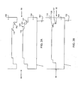
- FIGS. 2A and 2B An exploded view of interface 80 between outer ring 110 and outer sidewall 106 is shown in FIGS. 2A and 2B.
- FIG. 2A shows a line drawing of interface 80 of outer ring 110 and outer sidewall 106, exaggerated for purposes of explanation, with outer ring 110 and outer sidewall 106 not yet connected.
- interface 80 between sidewall 106 and ring 110 includes mechanical axial and radial stops 107, 109, i.e., an interconnection of a series of male steps which engage in corresponding female steps of the complementary part.
- mechanical axial stop 107 can be formed by outer ring 110 including a first female step 112 and outer sidewall 106 including a corresponding first male step 114.
- Mechanical radial stop 109 can be formed by outer ring 110 having a second female step 116, adjacent to first female step 112, and outer sidewall 106 including a corresponding second male step 118, adjacent to first male step 114.
- FIG. 2B shows an exploded view of interface 80 of outer ring 110 and outer sidewall 106 after coupling, including mechanical radial stop 109 and mechanical radial stop 107.
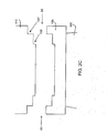
- mechanical axial stop 107 and mechanical radial stop 109 can be formed by reversing the interconnection of male steps which engage in the female steps of the complementary part.
- outer sidewall 106 includes central male steps and outer ring 110 is shown with central female steps, the reverse, as shown in FIG. 2C , is also disclosed.
- Outer sidewall 106 may instead include central female steps, while outer ring 110 can include central male steps.
- the female and male steps are shown in the two-dimensional figures as substantially horizontal, these parts may also be angled to assist proper placement of the parts of the nozzle assembly.
- FIG. 3 Another embodiment of interface 80 between outer sidewall 106 and outer ring 110 of nozzle assembly 100 according to an embodiment of the invention is disclosed in FIG. 3 .
- outer sidewall 106 is coupled to outer ring 110 through interface 80 that, as discussed above, includes an interconnection of male steps which engage in the corresponding female steps of the complementary part to provide mechanical axial stop 109 and mechanical radial stop 107.
- one or more surfaces at interface 80 can be angled away from the interface to form a narrow groove 120.
- a portion of outer ring 110 shown as portion 111, is angled away from interface 80 to form narrow groove 120.
- Narrow groove 120 can be formed by angling portion 111 of outer ring 110 at an angle in the range of approximately 0° to approximately 11°. While outer ring 110 is shown as having portion 111 angled away from interface 80, outer sidewall 106 could instead have a portion angled away from interface 80.
- outer ring 110 can further include a protruding consumable root portion 122 that extends toward interface 80 between outer sidewall 106 and outer ring 110.
- Consumable root portion 122 can include a material having any shape and size suitable for facilitating a weld at interface 80 between outer ring 110 and outer sidewall 106.
- consumable root portion 122 can include a chamfer, or a square bottom groove.
- Consumable root portion 122 can act as a consumable root for a weld, such as a TIG weld or can act as a fixturing stop for a weld, such as an electron beam weld (EBW), to ensure that the parts remain in the correct position.
- EBW electron beam weld
- outer ring 110 and outer sidewall 106 can be welded together using conventional low heat welding techniques
- the nozzle assembly of this disclosure also allows for high heat welds, such as GTAW (either using an energized or non-energized filler wire), GMAW or EBW. If a GTAW (also known as TIG) weld is used, a manual TIG weld or fully-automated TIG weld can be used.
- GTAW also known as TIG
- TIG weld a manual TIG weld or fully-automated TIG weld can be used.
- the stress concentration on the root of a weld between outer sidewall 106 and outer ring 110 is in a substantially vertical direction.
- the ratio of weld depth to width of the weld is preferably in the range of approximately 3:1 to 10:1.
- an edge of outer sidewall 106, shown as portion 105, that abuts outer ring 110 is also angled away from interface 80.
- the embodiment shown in FIG. 4 includes both surfaces 105, 111 angled away from interface 80 to form narrow groove 120.
- portion 105 can be angled away from interface 80 at an angle in the range of approximately 0° to approximately 11°.
- first,” “second,” and the like, herein do not denote any order, quantity, or importance, but rather are used to distinguish one element from another, and the terms “a” and “an” herein do not denote a limitation of quantity, but rather denote the presence of at least one of the referenced item.
- the modifier “about” used in connection with a quantity is inclusive of the stated value and has the meaning dictated by the context, (e.g., includes the degree of error associated with measurement of the particular quantity).
- suffix "(s)” as used herein is intended to include both the singular and the plural of the term that it modifies, thereby including one or more of that term (e.g., the metal(s) includes one or more metals).
- Ranges disclosed herein are inclusive and independently combinable (e.g., ranges of "up to about 25 wt%, or, more specifically, about 5 wt% to about 20 wt %", is inclusive of the endpoints and all intermediate values of the ranges of "about 5 wt% to about 25 wt%,” etc).
Landscapes
- Engineering & Computer Science (AREA)
- Mechanical Engineering (AREA)
- General Engineering & Computer Science (AREA)
- Turbine Rotor Nozzle Sealing (AREA)
Applications Claiming Priority (1)
| Application Number | Priority Date | Filing Date | Title |
|---|---|---|---|
| US12/402,066 US8118550B2 (en) | 2009-03-11 | 2009-03-11 | Turbine singlet nozzle assembly with radial stop and narrow groove |
Publications (3)
| Publication Number | Publication Date |
|---|---|
| EP2256298A2 true EP2256298A2 (fr) | 2010-12-01 |
| EP2256298A3 EP2256298A3 (fr) | 2014-12-24 |
| EP2256298B1 EP2256298B1 (fr) | 2016-08-10 |
Family
ID=42730844
Family Applications (1)
| Application Number | Title | Priority Date | Filing Date |
|---|---|---|---|
| EP10155881.5A Active EP2256298B1 (fr) | 2009-03-11 | 2010-03-09 | Ensemble de buse de singulet de turbine avec arrêt radial et rainure |
Country Status (4)
| Country | Link |
|---|---|
| US (1) | US8118550B2 (fr) |
| EP (1) | EP2256298B1 (fr) |
| JP (1) | JP5709388B2 (fr) |
| CN (1) | CN101839498B (fr) |
Families Citing this family (3)
| Publication number | Priority date | Publication date | Assignee | Title |
|---|---|---|---|---|
| US8562292B2 (en) * | 2010-12-02 | 2013-10-22 | General Electric Company | Steam turbine singlet interface for margin stage nozzles with pinned or bolted inner ring |
| US8684697B2 (en) * | 2010-12-13 | 2014-04-01 | General Electric Company | Steam turbine singlet nozzle design for breech loaded assembly |
| CN104213948A (zh) * | 2014-08-28 | 2014-12-17 | 浙江鸿峰重工机械有限公司 | 一种汽轮机用隔板 |
Family Cites Families (21)
| Publication number | Priority date | Publication date | Assignee | Title |
|---|---|---|---|---|
| US2245237A (en) * | 1939-12-13 | 1941-06-10 | Gen Electric | Elastic fluid turbine diaphragm |
| US4684320A (en) * | 1984-12-13 | 1987-08-04 | United Technologies Corporation | Axial flow compressor case |
| US4889470A (en) * | 1988-08-01 | 1989-12-26 | Westinghouse Electric Corp. | Compressor diaphragm assembly |
| US5669757A (en) * | 1995-11-30 | 1997-09-23 | General Electric Company | Turbine nozzle retainer assembly |
| US6354797B1 (en) | 2000-07-27 | 2002-03-12 | General Electric Company | Brazeless fillet turbine nozzle |
| GB0226690D0 (en) * | 2002-11-15 | 2002-12-24 | Rolls Royce Plc | Vane with modified base |
| US6932568B2 (en) | 2003-02-27 | 2005-08-23 | General Electric Company | Turbine nozzle segment cantilevered mount |
| US6773229B1 (en) * | 2003-03-14 | 2004-08-10 | General Electric Company | Turbine nozzle having angel wing seal lands and associated welding method |
| US6916154B2 (en) * | 2003-04-29 | 2005-07-12 | Pratt & Whitney Canada Corp. | Diametrically energized piston ring |
| US6908279B2 (en) * | 2003-11-25 | 2005-06-21 | General Electric Company | Method of installing stationary blades of a turbine and turbine structure having a radial loading pin |
| DE102004006706A1 (de) * | 2004-02-11 | 2005-08-25 | Mtu Aero Engines Gmbh | Dämpfungsanordnung für Leifschaufeln |
| WO2007039396A1 (fr) * | 2005-10-06 | 2007-04-12 | Alstom Technology Ltd | Systeme d'aubes directrices d'une turbomachine |
| US7329096B2 (en) | 2005-10-18 | 2008-02-12 | General Electric Company | Machine tooled diaphragm partitions and nozzles |
| GB2434182A (en) * | 2006-01-11 | 2007-07-18 | Rolls Royce Plc | Guide vane arrangement for a gas turbine engine |
| US8702385B2 (en) * | 2006-01-13 | 2014-04-22 | General Electric Company | Welded nozzle assembly for a steam turbine and assembly fixtures |
| US7997860B2 (en) * | 2006-01-13 | 2011-08-16 | General Electric Company | Welded nozzle assembly for a steam turbine and related assembly fixtures |
| US7427187B2 (en) * | 2006-01-13 | 2008-09-23 | General Electric Company | Welded nozzle assembly for a steam turbine and methods of assembly |
| JP4918263B2 (ja) * | 2006-01-27 | 2012-04-18 | 三菱重工業株式会社 | 軸流圧縮機の静翼環 |
| US7874795B2 (en) * | 2006-09-11 | 2011-01-25 | General Electric Company | Turbine nozzle assemblies |
| US8262359B2 (en) * | 2007-01-12 | 2012-09-11 | Alstom Technology Ltd. | Diaphragm for turbomachines and method of manufacture |
| US20110200430A1 (en) * | 2010-02-16 | 2011-08-18 | General Electric Company | Steam turbine nozzle segment having arcuate interface |
-
2009
- 2009-03-11 US US12/402,066 patent/US8118550B2/en active Active
-
2010
- 2010-03-05 JP JP2010048500A patent/JP5709388B2/ja active Active
- 2010-03-09 EP EP10155881.5A patent/EP2256298B1/fr active Active
- 2010-03-10 CN CN201010143907.5A patent/CN101839498B/zh active Active
Non-Patent Citations (1)
| Title |
|---|
| None |
Also Published As
| Publication number | Publication date |
|---|---|
| US8118550B2 (en) | 2012-02-21 |
| JP5709388B2 (ja) | 2015-04-30 |
| JP2010209914A (ja) | 2010-09-24 |
| EP2256298A3 (fr) | 2014-12-24 |
| CN101839498A (zh) | 2010-09-22 |
| EP2256298B1 (fr) | 2016-08-10 |
| US20100232956A1 (en) | 2010-09-16 |
| CN101839498B (zh) | 2014-02-12 |
Similar Documents
| Publication | Publication Date | Title |
|---|---|---|
| US8070429B2 (en) | Turbine singlet nozzle assembly with mechanical and weld fabrication | |
| EP1808577B1 (fr) | Ensemble d'aubes statoriques soudées pour turbine à vapeur | |
| US7761990B2 (en) | Method of repairing a stationary airfoil array directing three-dimensional flow | |
| US20110200430A1 (en) | Steam turbine nozzle segment having arcuate interface | |
| JP5557433B2 (ja) | 蒸気タービン用の溶接ノズルアセンブリ及びそれに関連する組立固定具 | |
| US8702385B2 (en) | Welded nozzle assembly for a steam turbine and assembly fixtures | |
| EP3034800B1 (fr) | Élément d'aubage pour une machine d'écoulement de fluide | |
| EP1132166B1 (fr) | Ensemble avec ailette et stator pour une turbine et procédé pour la fabrication de cet ensemble | |
| JP2005501992A (ja) | 静翼または動翼構成要素の製造方法 | |
| WO2017074373A1 (fr) | Aube de turbine à gaz en composite métal-céramique | |
| EP2256298B1 (fr) | Ensemble de buse de singulet de turbine avec arrêt radial et rainure | |
| EP3112598A1 (fr) | Segment de tuyère de turbine à vapeur pour application à arc partiel, ensemble associé et turbine à vapeur | |
| EP2883651B1 (fr) | Procédé de fabrication d'une aube de turbine à vapeur équipée d'un écran de protection contre l'érosion par soudage par faisceau d'électron utilisant un matériau d'apport |
Legal Events
| Date | Code | Title | Description |
|---|---|---|---|
| PUAI | Public reference made under article 153(3) epc to a published international application that has entered the european phase |
Free format text: ORIGINAL CODE: 0009012 |
|
| AK | Designated contracting states |
Kind code of ref document: A2 Designated state(s): AT BE BG CH CY CZ DE DK EE ES FI FR GB GR HR HU IE IS IT LI LT LU LV MC MK MT NL NO PL PT RO SE SI SK SM TR |
|
| PUAL | Search report despatched |
Free format text: ORIGINAL CODE: 0009013 |
|
| AK | Designated contracting states |
Kind code of ref document: A3 Designated state(s): AT BE BG CH CY CZ DE DK EE ES FI FR GB GR HR HU IE IS IT LI LT LU LV MC MK MT NL NO PL PT RO SE SI SK SM TR |
|
| RIC1 | Information provided on ipc code assigned before grant |
Ipc: F01D 9/04 20060101AFI20141117BHEP |
|
| 17P | Request for examination filed |
Effective date: 20150624 |
|
| RBV | Designated contracting states (corrected) |
Designated state(s): AT BE BG CH CY CZ DE DK EE ES FI FR GB GR HR HU IE IS IT LI LT LU LV MC MK MT NL NO PL PT RO SE SI SK SM TR |
|
| 17Q | First examination report despatched |
Effective date: 20151127 |
|
| GRAP | Despatch of communication of intention to grant a patent |
Free format text: ORIGINAL CODE: EPIDOSNIGR1 |
|
| INTG | Intention to grant announced |
Effective date: 20160510 |
|
| GRAS | Grant fee paid |
Free format text: ORIGINAL CODE: EPIDOSNIGR3 |
|
| GRAA | (expected) grant |
Free format text: ORIGINAL CODE: 0009210 |
|
| AK | Designated contracting states |
Kind code of ref document: B1 Designated state(s): AT BE BG CH CY CZ DE DK EE ES FI FR GB GR HR HU IE IS IT LI LT LU LV MC MK MT NL NO PL PT RO SE SI SK SM TR |
|
| REG | Reference to a national code |
Ref country code: GB Ref legal event code: FG4D |
|
| REG | Reference to a national code |
Ref country code: CH Ref legal event code: EP Ref country code: AT Ref legal event code: REF Ref document number: 819255 Country of ref document: AT Kind code of ref document: T Effective date: 20160815 |
|
| REG | Reference to a national code |
Ref country code: IE Ref legal event code: FG4D |
|
| REG | Reference to a national code |
Ref country code: DE Ref legal event code: R096 Ref document number: 602010035280 Country of ref document: DE |
|
| REG | Reference to a national code |
Ref country code: LT Ref legal event code: MG4D |
|
| REG | Reference to a national code |
Ref country code: NL Ref legal event code: MP Effective date: 20160810 |
|
| REG | Reference to a national code |
Ref country code: AT Ref legal event code: MK05 Ref document number: 819255 Country of ref document: AT Kind code of ref document: T Effective date: 20160810 |
|
| PG25 | Lapsed in a contracting state [announced via postgrant information from national office to epo] |
Ref country code: FI Free format text: LAPSE BECAUSE OF FAILURE TO SUBMIT A TRANSLATION OF THE DESCRIPTION OR TO PAY THE FEE WITHIN THE PRESCRIBED TIME-LIMIT Effective date: 20160810 Ref country code: NL Free format text: LAPSE BECAUSE OF FAILURE TO SUBMIT A TRANSLATION OF THE DESCRIPTION OR TO PAY THE FEE WITHIN THE PRESCRIBED TIME-LIMIT Effective date: 20160810 Ref country code: LT Free format text: LAPSE BECAUSE OF FAILURE TO SUBMIT A TRANSLATION OF THE DESCRIPTION OR TO PAY THE FEE WITHIN THE PRESCRIBED TIME-LIMIT Effective date: 20160810 Ref country code: HR Free format text: LAPSE BECAUSE OF FAILURE TO SUBMIT A TRANSLATION OF THE DESCRIPTION OR TO PAY THE FEE WITHIN THE PRESCRIBED TIME-LIMIT Effective date: 20160810 Ref country code: NO Free format text: LAPSE BECAUSE OF FAILURE TO SUBMIT A TRANSLATION OF THE DESCRIPTION OR TO PAY THE FEE WITHIN THE PRESCRIBED TIME-LIMIT Effective date: 20161110 Ref country code: IS Free format text: LAPSE BECAUSE OF FAILURE TO SUBMIT A TRANSLATION OF THE DESCRIPTION OR TO PAY THE FEE WITHIN THE PRESCRIBED TIME-LIMIT Effective date: 20161210 |
|
| PG25 | Lapsed in a contracting state [announced via postgrant information from national office to epo] |
Ref country code: SE Free format text: LAPSE BECAUSE OF FAILURE TO SUBMIT A TRANSLATION OF THE DESCRIPTION OR TO PAY THE FEE WITHIN THE PRESCRIBED TIME-LIMIT Effective date: 20160810 Ref country code: LV Free format text: LAPSE BECAUSE OF FAILURE TO SUBMIT A TRANSLATION OF THE DESCRIPTION OR TO PAY THE FEE WITHIN THE PRESCRIBED TIME-LIMIT Effective date: 20160810 Ref country code: PT Free format text: LAPSE BECAUSE OF FAILURE TO SUBMIT A TRANSLATION OF THE DESCRIPTION OR TO PAY THE FEE WITHIN THE PRESCRIBED TIME-LIMIT Effective date: 20161212 Ref country code: AT Free format text: LAPSE BECAUSE OF FAILURE TO SUBMIT A TRANSLATION OF THE DESCRIPTION OR TO PAY THE FEE WITHIN THE PRESCRIBED TIME-LIMIT Effective date: 20160810 Ref country code: GR Free format text: LAPSE BECAUSE OF FAILURE TO SUBMIT A TRANSLATION OF THE DESCRIPTION OR TO PAY THE FEE WITHIN THE PRESCRIBED TIME-LIMIT Effective date: 20161111 Ref country code: ES Free format text: LAPSE BECAUSE OF FAILURE TO SUBMIT A TRANSLATION OF THE DESCRIPTION OR TO PAY THE FEE WITHIN THE PRESCRIBED TIME-LIMIT Effective date: 20160810 Ref country code: PL Free format text: LAPSE BECAUSE OF FAILURE TO SUBMIT A TRANSLATION OF THE DESCRIPTION OR TO PAY THE FEE WITHIN THE PRESCRIBED TIME-LIMIT Effective date: 20160810 |
|
| PG25 | Lapsed in a contracting state [announced via postgrant information from national office to epo] |
Ref country code: RO Free format text: LAPSE BECAUSE OF FAILURE TO SUBMIT A TRANSLATION OF THE DESCRIPTION OR TO PAY THE FEE WITHIN THE PRESCRIBED TIME-LIMIT Effective date: 20160810 Ref country code: EE Free format text: LAPSE BECAUSE OF FAILURE TO SUBMIT A TRANSLATION OF THE DESCRIPTION OR TO PAY THE FEE WITHIN THE PRESCRIBED TIME-LIMIT Effective date: 20160810 |
|
| PGFP | Annual fee paid to national office [announced via postgrant information from national office to epo] |
Ref country code: CH Payment date: 20170327 Year of fee payment: 8 |
|
| REG | Reference to a national code |
Ref country code: DE Ref legal event code: R097 Ref document number: 602010035280 Country of ref document: DE |
|
| PG25 | Lapsed in a contracting state [announced via postgrant information from national office to epo] |
Ref country code: BE Free format text: LAPSE BECAUSE OF FAILURE TO SUBMIT A TRANSLATION OF THE DESCRIPTION OR TO PAY THE FEE WITHIN THE PRESCRIBED TIME-LIMIT Effective date: 20160810 Ref country code: DK Free format text: LAPSE BECAUSE OF FAILURE TO SUBMIT A TRANSLATION OF THE DESCRIPTION OR TO PAY THE FEE WITHIN THE PRESCRIBED TIME-LIMIT Effective date: 20160810 Ref country code: BG Free format text: LAPSE BECAUSE OF FAILURE TO SUBMIT A TRANSLATION OF THE DESCRIPTION OR TO PAY THE FEE WITHIN THE PRESCRIBED TIME-LIMIT Effective date: 20161110 Ref country code: SK Free format text: LAPSE BECAUSE OF FAILURE TO SUBMIT A TRANSLATION OF THE DESCRIPTION OR TO PAY THE FEE WITHIN THE PRESCRIBED TIME-LIMIT Effective date: 20160810 Ref country code: CZ Free format text: LAPSE BECAUSE OF FAILURE TO SUBMIT A TRANSLATION OF THE DESCRIPTION OR TO PAY THE FEE WITHIN THE PRESCRIBED TIME-LIMIT Effective date: 20160810 Ref country code: SM Free format text: LAPSE BECAUSE OF FAILURE TO SUBMIT A TRANSLATION OF THE DESCRIPTION OR TO PAY THE FEE WITHIN THE PRESCRIBED TIME-LIMIT Effective date: 20160810 |
|
| PLBE | No opposition filed within time limit |
Free format text: ORIGINAL CODE: 0009261 |
|
| STAA | Information on the status of an ep patent application or granted ep patent |
Free format text: STATUS: NO OPPOSITION FILED WITHIN TIME LIMIT |
|
| 26N | No opposition filed |
Effective date: 20170511 |
|
| PG25 | Lapsed in a contracting state [announced via postgrant information from national office to epo] |
Ref country code: SI Free format text: LAPSE BECAUSE OF FAILURE TO SUBMIT A TRANSLATION OF THE DESCRIPTION OR TO PAY THE FEE WITHIN THE PRESCRIBED TIME-LIMIT Effective date: 20160810 |
|
| GBPC | Gb: european patent ceased through non-payment of renewal fee |
Effective date: 20170309 |
|
| PG25 | Lapsed in a contracting state [announced via postgrant information from national office to epo] |
Ref country code: MC Free format text: LAPSE BECAUSE OF FAILURE TO SUBMIT A TRANSLATION OF THE DESCRIPTION OR TO PAY THE FEE WITHIN THE PRESCRIBED TIME-LIMIT Effective date: 20160810 |
|
| REG | Reference to a national code |
Ref country code: IE Ref legal event code: MM4A |
|
| REG | Reference to a national code |
Ref country code: FR Ref legal event code: ST Effective date: 20171130 |
|
| PG25 | Lapsed in a contracting state [announced via postgrant information from national office to epo] |
Ref country code: FR Free format text: LAPSE BECAUSE OF NON-PAYMENT OF DUE FEES Effective date: 20170331 Ref country code: LU Free format text: LAPSE BECAUSE OF NON-PAYMENT OF DUE FEES Effective date: 20170309 |
|
| PG25 | Lapsed in a contracting state [announced via postgrant information from national office to epo] |
Ref country code: IE Free format text: LAPSE BECAUSE OF NON-PAYMENT OF DUE FEES Effective date: 20170309 Ref country code: GB Free format text: LAPSE BECAUSE OF NON-PAYMENT OF DUE FEES Effective date: 20170309 |
|
| PG25 | Lapsed in a contracting state [announced via postgrant information from national office to epo] |
Ref country code: MT Free format text: LAPSE BECAUSE OF NON-PAYMENT OF DUE FEES Effective date: 20170309 |
|
| REG | Reference to a national code |
Ref country code: CH Ref legal event code: PL |
|
| PG25 | Lapsed in a contracting state [announced via postgrant information from national office to epo] |
Ref country code: CH Free format text: LAPSE BECAUSE OF NON-PAYMENT OF DUE FEES Effective date: 20180331 Ref country code: LI Free format text: LAPSE BECAUSE OF NON-PAYMENT OF DUE FEES Effective date: 20180331 |
|
| PG25 | Lapsed in a contracting state [announced via postgrant information from national office to epo] |
Ref country code: HU Free format text: LAPSE BECAUSE OF FAILURE TO SUBMIT A TRANSLATION OF THE DESCRIPTION OR TO PAY THE FEE WITHIN THE PRESCRIBED TIME-LIMIT; INVALID AB INITIO Effective date: 20100309 |
|
| PG25 | Lapsed in a contracting state [announced via postgrant information from national office to epo] |
Ref country code: CY Free format text: LAPSE BECAUSE OF NON-PAYMENT OF DUE FEES Effective date: 20160810 |
|
| PG25 | Lapsed in a contracting state [announced via postgrant information from national office to epo] |
Ref country code: MK Free format text: LAPSE BECAUSE OF FAILURE TO SUBMIT A TRANSLATION OF THE DESCRIPTION OR TO PAY THE FEE WITHIN THE PRESCRIBED TIME-LIMIT Effective date: 20160810 |
|
| PG25 | Lapsed in a contracting state [announced via postgrant information from national office to epo] |
Ref country code: TR Free format text: LAPSE BECAUSE OF FAILURE TO SUBMIT A TRANSLATION OF THE DESCRIPTION OR TO PAY THE FEE WITHIN THE PRESCRIBED TIME-LIMIT Effective date: 20160810 |
|
| P01 | Opt-out of the competence of the unified patent court (upc) registered |
Effective date: 20230522 |
|
| REG | Reference to a national code |
Ref country code: DE Ref legal event code: R081 Ref document number: 602010035280 Country of ref document: DE Owner name: GENERAL ELECTRIC TECHNOLOGY GMBH, CH Free format text: FORMER OWNER: GENERAL ELECTRIC COMPANY, SCHENECTADY, NY, US |
|
| PGFP | Annual fee paid to national office [announced via postgrant information from national office to epo] |
Ref country code: DE Payment date: 20260219 Year of fee payment: 17 |
|
| PGFP | Annual fee paid to national office [announced via postgrant information from national office to epo] |
Ref country code: IT Payment date: 20260219 Year of fee payment: 17 |