EP2256308B1 - Spielausgleichselement - Google Patents
Spielausgleichselement Download PDFInfo
- Publication number
- EP2256308B1 EP2256308B1 EP09709467.6A EP09709467A EP2256308B1 EP 2256308 B1 EP2256308 B1 EP 2256308B1 EP 09709467 A EP09709467 A EP 09709467A EP 2256308 B1 EP2256308 B1 EP 2256308B1
- Authority
- EP
- European Patent Office
- Prior art keywords
- valve
- pressure chamber
- plunger
- valve element
- high pressure
- Prior art date
- Legal status (The legal status is an assumption and is not a legal conclusion. Google has not performed a legal analysis and makes no representation as to the accuracy of the status listed.)
- Not-in-force
Links
- 239000012530 fluid Substances 0.000 claims description 26
- 230000008961 swelling Effects 0.000 claims description 3
- 230000001965 increasing effect Effects 0.000 description 7
- 239000003921 oil Substances 0.000 description 6
- 229910000831 Steel Inorganic materials 0.000 description 3
- 230000002411 adverse Effects 0.000 description 3
- 238000006073 displacement reaction Methods 0.000 description 3
- 239000002184 metal Substances 0.000 description 3
- 229910052751 metal Inorganic materials 0.000 description 3
- 239000010959 steel Substances 0.000 description 3
- 238000002485 combustion reaction Methods 0.000 description 2
- 230000002708 enhancing effect Effects 0.000 description 2
- 230000005484 gravity Effects 0.000 description 2
- 230000000717 retained effect Effects 0.000 description 2
- 230000000630 rising effect Effects 0.000 description 2
- 229910052581 Si3N4 Inorganic materials 0.000 description 1
- 239000000919 ceramic Substances 0.000 description 1
- 230000006835 compression Effects 0.000 description 1
- 238000007906 compression Methods 0.000 description 1
- 230000000694 effects Effects 0.000 description 1
- 150000002739 metals Chemical class 0.000 description 1
- 230000002093 peripheral effect Effects 0.000 description 1
- HQVNEWCFYHHQES-UHFFFAOYSA-N silicon nitride Chemical compound N12[Si]34N5[Si]62N3[Si]51N64 HQVNEWCFYHHQES-UHFFFAOYSA-N 0.000 description 1
Images


Classifications
-
- F—MECHANICAL ENGINEERING; LIGHTING; HEATING; WEAPONS; BLASTING
- F01—MACHINES OR ENGINES IN GENERAL; ENGINE PLANTS IN GENERAL; STEAM ENGINES
- F01L—CYCLICALLY OPERATING VALVES FOR MACHINES OR ENGINES
- F01L1/00—Valve-gear or valve arrangements, e.g. lift-valve gear
- F01L1/20—Adjusting or compensating clearance
- F01L1/22—Adjusting or compensating clearance automatically, e.g. mechanically
- F01L1/24—Adjusting or compensating clearance automatically, e.g. mechanically by fluid means, e.g. hydraulically
- F01L1/2405—Adjusting or compensating clearance automatically, e.g. mechanically by fluid means, e.g. hydraulically by means of a hydraulic adjusting device located between the cylinder head and rocker arm
-
- F—MECHANICAL ENGINEERING; LIGHTING; HEATING; WEAPONS; BLASTING
- F01—MACHINES OR ENGINES IN GENERAL; ENGINE PLANTS IN GENERAL; STEAM ENGINES
- F01L—CYCLICALLY OPERATING VALVES FOR MACHINES OR ENGINES
- F01L1/00—Valve-gear or valve arrangements, e.g. lift-valve gear
- F01L1/20—Adjusting or compensating clearance
- F01L1/22—Adjusting or compensating clearance automatically, e.g. mechanically
- F01L1/24—Adjusting or compensating clearance automatically, e.g. mechanically by fluid means, e.g. hydraulically
- F01L1/2411—Adjusting or compensating clearance automatically, e.g. mechanically by fluid means, e.g. hydraulically by means of a hydraulic adjusting device located between the valve stem and rocker arm
-
- F—MECHANICAL ENGINEERING; LIGHTING; HEATING; WEAPONS; BLASTING
- F01—MACHINES OR ENGINES IN GENERAL; ENGINE PLANTS IN GENERAL; STEAM ENGINES
- F01L—CYCLICALLY OPERATING VALVES FOR MACHINES OR ENGINES
- F01L1/00—Valve-gear or valve arrangements, e.g. lift-valve gear
- F01L1/20—Adjusting or compensating clearance
- F01L1/22—Adjusting or compensating clearance automatically, e.g. mechanically
- F01L1/24—Adjusting or compensating clearance automatically, e.g. mechanically by fluid means, e.g. hydraulically
- F01L1/2416—Adjusting or compensating clearance automatically, e.g. mechanically by fluid means, e.g. hydraulically by means of a hydraulic adjusting device attached to an articulated rocker
-
- F—MECHANICAL ENGINEERING; LIGHTING; HEATING; WEAPONS; BLASTING
- F01—MACHINES OR ENGINES IN GENERAL; ENGINE PLANTS IN GENERAL; STEAM ENGINES
- F01L—CYCLICALLY OPERATING VALVES FOR MACHINES OR ENGINES
- F01L1/00—Valve-gear or valve arrangements, e.g. lift-valve gear
- F01L1/20—Adjusting or compensating clearance
- F01L1/22—Adjusting or compensating clearance automatically, e.g. mechanically
- F01L1/24—Adjusting or compensating clearance automatically, e.g. mechanically by fluid means, e.g. hydraulically
- F01L1/2422—Adjusting or compensating clearance automatically, e.g. mechanically by fluid means, e.g. hydraulically by means or a hydraulic adjusting device located between the push rod and rocker arm
-
- F—MECHANICAL ENGINEERING; LIGHTING; HEATING; WEAPONS; BLASTING
- F01—MACHINES OR ENGINES IN GENERAL; ENGINE PLANTS IN GENERAL; STEAM ENGINES
- F01L—CYCLICALLY OPERATING VALVES FOR MACHINES OR ENGINES
- F01L1/00—Valve-gear or valve arrangements, e.g. lift-valve gear
- F01L1/20—Adjusting or compensating clearance
- F01L1/22—Adjusting or compensating clearance automatically, e.g. mechanically
- F01L1/24—Adjusting or compensating clearance automatically, e.g. mechanically by fluid means, e.g. hydraulically
- F01L1/245—Hydraulic tappets
- F01L1/25—Hydraulic tappets between cam and valve stem
-
- F—MECHANICAL ENGINEERING; LIGHTING; HEATING; WEAPONS; BLASTING
- F01—MACHINES OR ENGINES IN GENERAL; ENGINE PLANTS IN GENERAL; STEAM ENGINES
- F01L—CYCLICALLY OPERATING VALVES FOR MACHINES OR ENGINES
- F01L1/00—Valve-gear or valve arrangements, e.g. lift-valve gear
- F01L1/20—Adjusting or compensating clearance
- F01L1/22—Adjusting or compensating clearance automatically, e.g. mechanically
- F01L1/24—Adjusting or compensating clearance automatically, e.g. mechanically by fluid means, e.g. hydraulically
- F01L1/245—Hydraulic tappets
- F01L1/255—Hydraulic tappets between cam and rocker arm
-
- F—MECHANICAL ENGINEERING; LIGHTING; HEATING; WEAPONS; BLASTING
- F01—MACHINES OR ENGINES IN GENERAL; ENGINE PLANTS IN GENERAL; STEAM ENGINES
- F01L—CYCLICALLY OPERATING VALVES FOR MACHINES OR ENGINES
- F01L2301/00—Using particular materials
-
- F—MECHANICAL ENGINEERING; LIGHTING; HEATING; WEAPONS; BLASTING
- F01—MACHINES OR ENGINES IN GENERAL; ENGINE PLANTS IN GENERAL; STEAM ENGINES
- F01L—CYCLICALLY OPERATING VALVES FOR MACHINES OR ENGINES
- F01L2301/00—Using particular materials
- F01L2301/02—Using ceramic materials
-
- F—MECHANICAL ENGINEERING; LIGHTING; HEATING; WEAPONS; BLASTING
- F01—MACHINES OR ENGINES IN GENERAL; ENGINE PLANTS IN GENERAL; STEAM ENGINES
- F01L—CYCLICALLY OPERATING VALVES FOR MACHINES OR ENGINES
- F01L2303/00—Manufacturing of components used in valve arrangements
-
- F—MECHANICAL ENGINEERING; LIGHTING; HEATING; WEAPONS; BLASTING
- F01—MACHINES OR ENGINES IN GENERAL; ENGINE PLANTS IN GENERAL; STEAM ENGINES
- F01L—CYCLICALLY OPERATING VALVES FOR MACHINES OR ENGINES
- F01L2820/00—Details on specific features characterising valve gear arrangements
- F01L2820/01—Absolute values
Definitions
- the present invention relates to a hydraulic lash adjuster.
- Japanese Patent Application Publication JP-A-405 - 288020 discloses a hydraulic lash adjuster used in valve gears.
- the lash adjuster comprises a bottomed cylindrical body and a bottomed cylindrical plunger which is accommodated in the body so as to be movable upward and downward.
- the plunger has an upper end which protrudes out of the body and is adapted to support a rocker arm.
- the plunger has an interior serving as a low pressure chamber, and the body includes a lower interior that is partitioned by a bottom wall of the plunger thereby to serve as a high pressure chamber.
- the bottom wall of the plunger has an opening serving as a valve hole of a check valve.
- a hydraulic fluid is supplied into the low pressure chamber, and part of the hydraulic fluid in the low pressure chamber is caused to flow through the valve hole into the high pressure chamber, filling the high pressure chamber.
- the high pressure chamber also accommodates a valve element constituting a check valve and a valve spring biasing the valve element to the valve hole side (a valve-closed direction). When the plunger stands still, the bias of the valve spring holds the valve element in a valve-closed position where the valve hole is closed by the valve element, whereupon the check valve is closed.
- Increasing a biasing force of the valve spring is considered as a means for enhancing return of the valve element to the valve-closed position. In this case, however, there is a possibility that the valve element is kept closing the valve hole or that an opening degree of the valve hole becomes insufficient such that a smooth upward movement of the plunger is adversely affected.
- GB 2 185 549 A discloses a lash adjuster including a valve cage which is provided in a pressure chamber so as to be moveable upward and downward together with the plunger.
- the valve cage includes a base plate on which a check valve ball is placed, a cylindrical portion extending upward from a peripheral edge of the base plate thereby to surround the check valve ball, a flange protruding sideways from an upper end of the cylindrical portion thereby to be engaged with the plunger, and an opening formed through the cylindrical portion.
- the base plate has a central portion on which the check valve ball is placed and which has an upper surface convexed.
- EP 1 710 401 A1 discloses a valve system for a combustion engine in which a rocker arm abuts against an engine valve via a hydraulic tappet.
- the hydraulic tappet includes a plunger slideably fitted into a mounting hole of the tappet and a cylindrical member slideably fitted into the plunger.
- a dividing wall integrally formed with a portion of the cylindrical member forms a hydraulic chamber between itself and a closed end of the plunger, thereby separating the hydraulic chamber from a reservoir chamber.
- EP 0 608 925 A1 discloses a generic valve-lifter comprising a hydraulic adjusting element including a plunger, a check-ball, a ball cage, a ball spring and a plunger spring in order to control the opening and closing of respective valves.
- JP S61-185607 discloses a valve lift comprising a plunger body and a lift plunger that form a reservoir and a pressure oil chamber.
- An oil communication hole is defined between the reservoir and the pressure oil chamber, and a check ball is provided to restrict the oil returned from the pressure oil chamber through the oil communication hole to the reservoir.
- EP 1 586 747 A1 discloses a reverse spring hydraulic valve having a hydraulic control piston in a bore and with a reverse spring hydraulic valve in its base.
- the valve element moves axially inside a cylindrical guide, which is part of a retaining cap that limits the axial and radial movement of the valve element.
- the cap has an outer flange pressed into a stepped recess of the piston base by a large spring while the valve element is pressed into the open setting by a smaller spring between the valve element and a stepped profile in the base of the piston.
- the base of the cap limits the displacement of the valve element and has a ring of flow holes around the contact point with the valve element.
- DE 10 2005 022456 A1 discloses a hydraulic support element for a valve gear.
- the hydraulic support element has supply chamber having a thin-walled tube like deflection element.
- the present invention was made in view of the above-described circumstances and an object thereof is to avoid delay in the movement of the valve element to the valve-closed position during downward movement of the plunger.
- the present invention provides a lash adjuster which comprises a bottomed cylindrical body; a bottomed cylindrical plunger which is movable upward and downward while being in sliding contact with an inner circumferential surface of the body and which is biased upward by a return spring; a low pressure chamber defined in the plunger for storing an operating fluid; a high pressure chamber defined in a hollow lower interior of the body and separated from the low pressure chamber by a bottom wall of the plunger, the high pressure chamber being filled with the operating fluid; and a check valve which allows the operating fluid to flow from the low pressure chamber into the high pressure chamber when in a valve-opened state and which cuts off flow of the operating fluid from the high pressure chamber into the low pressure chamber when in a valve-closed state, wherein the check valve includes a valve hole extending through the bottom wall of the plunger; a retainer disposed in the high pressure chamber so as to be moved upward and downward with the plunger; and a valve element which is vertically movable in the high
- the cylindrical portion has a plurality of openings formed circumferentially equiangularly.
- the lash adjuster is characterized in that the base plate includes a central portion on which the valve element is placed and which has a thicker portion formed by swelling an upper surface of the central portion.
- the valve element When the plunger is moved upward, the operating fluid in the low pressure chamber flows through the valve hole into the high pressure chamber while the valve element is retained at the valve-opened position by self-weight. In this case, the valve element is maintained on the retainer even if an ascend speed of the plunger is high. Accordingly, a distance between the valve element and the valve hole is not prevented from being increased. As a result, when the plunger subsequently starts descending, the valve element is promptly moved to the valve-closed position thereby to close the valve hole.
- the hydraulic lash adjuster 10 according to the embodiment is applied to a valve gear (not shown) of an internal combustion engine.
- the valve gear will first be described.
- the valve gear comprises a valve, the lash adjuster 10, a rocker arm and a cam. With rotation of the cam, the rocker arm moves the valve upward and downward while being swung vertically with an upper end of the lash adjuster 10 serving as a fulcrum, as well known in the art.
- the lash adjuster 10 comprises a body 11, a plunger 12 and a check valve 27.
- the body 11 includes a circular bottom wall 13 and a cylindrical circumferential wall 14 rising from a circumferential edge of the bottom wall 13 and is formed into a bottomed cylindrical shape.
- the body 11 is fixed in a mounting hole (not shown) which is open at an upper surface of a cylinder head (not shown).
- the circumferential wall 14 of the body 11 has an outer communication hole 15 formed therethrough.
- the communication hole 15 is located near an upper end of the circumferential wall 14 and communicates with an operating fluid supply path (not shown) provided in the cylinder head.
- the plunger 12 includes a circular bottom wall 17 and a cylindrical circumferential wall 18 rising from a circumferential edge of the bottom wall 17 and is formed into a bottomed cylindrical shape.
- the plunger 12 is fitted into the body 11 from above so as to be movable upward and downward while an outer circumferential surface thereof is in sliding contact with an inner circumferential surface of the body 11.
- the plunger 12 has an upper end protruding upward from an upper end of the body 11.
- the upper end of the plunger 12 is formed with a substantially semispherical (dome-shaped) support 19.
- the rocker arm is abutted against an outer surface (an upper surface) of the support 19 thereby to support the rocker arm at a fulcrum point thereof.
- the plunger 12 is adapted to be subjected to a downward load from the rocker arm.
- the circumferential wall 18 of the plunger 12 has an inner communication hole 23 formed therethrough.
- the outer and inner communication holes 15 and 23 communicate with each other through a circumferential communication path 22 formed between the inner circumference of the circumferential wall 14 of the body 11 and an outer circumference of the circumferential wall 18 of the plunger 12.
- a rib 21 is formed on an underside of the plunger 12 or the bottom wall 17 of the plunger 12 so as to protrude downward from an outer circumferential edge of the underside into a concentric circular shape.
- the plunger 12 has an interior serving as a low pressure chamber 24.
- a high pressure chamber 25 is provided in a hollow lower interior of the body 11 and separated from the low pressure chamber 24 by the bottom wall 17 of the plunger 12.
- a check valve 27 includes a valve hole 28, a retainer 30 and a valve element 29.
- the check valve 27 allows an operating fluid to flow from the low pressure chamber 24 into the high pressure chamber 25 through the valve hole 28 when in a valve-opened state.
- the check valve 27 cuts off flow of the operating fluid from the high pressure chamber 25 into the low pressure chamber 24 through the valve hole 28 when in a valve-closed state.
- the valve hole 28 is formed through the bottom wall 17 of the plunger 12 so as to be concentric with the bottom wall 17 and so as to extend vertically.
- the bottom wall 17 has an opening edge which is located at the lower side of the valve hole 28 (the high pressure chamber 25 side) and formed with a sheet surface 31 which has a generally quadrant arc-shaped section and is expanded downward (a form in which a diameter is rendered larger as the sheet surface 31 comes near the high pressure chamber 25 side).
- the retainer 30 includes a base plate 32 which is made of a metal and is circular in shape and concentric with the valve hole 28, a circular cylindrical portion 33 extending upward from an outer circumferential edge of the base plate 32, and a spring bracket 34 which extends so as to be folded from an upper edge of the cylindrical portion 33 to the outer circumferential side into a concentric and generally semicircular arc shape.
- the retainer 30 is formed into a bottomed cylindrical shape as a whole.
- the base plate 32 has a larger diameter than the valve element 29 and includes a central portion (namely, a region on which the valve element 29 occupying the valve-opened position is placed) with a thicker portion 35 which is formed by swelling an upper surface of the central portion into a concentric shape.
- the thicker portion 35 has a smaller diameter than the valve element 29 which will be described in detail later. Furthermore, the cylindrical portion 33 is formed into such a shape as to surround the valve element 29 accommodated in the retainer 30. The cylindrical portion 33 further has a plurality of openings 36 formed therethrough circumferentially equiangularly.
- the retainer 30 is disposed in the high pressure chamber 25 and mounted on the plunger 12 so that the spring bracket 34 is fitted with an inner circumference of the rib 21 and abutted against the underside of the bottom wall 17.
- a return spring 26 which comprises a compression coil spring and is coaxial with the valve hole 28 is accommodated in the high pressure chamber 25.
- the return spring 26 has a coil diameter which is smaller than an inner diameter of the rib 21 and larger than an outer diameter of the cylindrical portion 33 of the retainer 30.
- the return spring 26 has a lower end which is abutted on a bottom surface (the upper surface of the bottom wall 13) of the high pressure chamber 25 and an upper end which is abutted on a recessed underside of the spring bracket 34 thereby to be mounted between the retainer 30 and the bottom wall 13 of the body 11 in an elastically deflected state (an elastic restoring force stored state).
- the elastic restoring force of the return spring 26 biases the plunger 12 and the retainer 30 so that the plunger 12 and the retainer 30 are integrally moved upward relative to the body 11.
- the valve element 29 comprises a spherical member made of steel (SUJ2) and is disposed in the high pressure chamber 25.
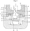
- the valve element 29 is held between a part of the bottom wall 17 located in the cylindrical portion 33 of the retainer 30 and the thicker portion 35 (the base plate 32) and is upwardly and downwardly movable by a slight distance between a valve-opened position (see FIG. 2 ) and the valve-closed position (see FIG. 3 ) located higher than the valve-opened position within a range from the aforesaid part of the bottom wall 17 and the thicker portion 35.
- the valve element 29 When occupying the valve-opened position, the valve element 29 is placed on the upper surface of the thicker portion 35.
- the valve element 29 When occupying the valve-closed position, the valve element 29 is abutted on the sheet surface 31 in a liquid-tight manner thereby to close the valve hole 28.
- the upper end of the valve element 29 is kept surrounded by the sheet surface 31 even when the valve element 29 occupies either valve-opened or valve-closed position.
- a horizontal gap between the valve element 29 and the sheet surface 31 becomes maximum.
- the aforesaid horizontal direction is perpendicular to the movement direction between the valve-opened and valve-closed positions of the valve element 29.
- the gap is small, there is no possibility that the valve element 29 is horizontally displaced to a large extent or deviated from the valve hole 28 to a large extent.
- the sheet surface 31 has a function of guiding the valve element 29.
- the inner diameter A of the valve hole 28 ranges from 2 to 2.2 mm.
- the valve element 29 has a diameter B that is 3 mm and larger than the inner diameter A of the valve hole 28.
- a vertical stroke C between the valve-opened and valve-closed positions of the valve element 29 ranges from 0.05 to 0.2 mm.
- a diameter D of abutment area (abutment circle) between the valve element 29 and the sheet surface 31 is 2.38 mm when the valve element 29 is located at the valve-closed position.
- a minimum gap E between the valve element 29 and the sheet surface 31 ranges from 0.05 to 0.2 mm when the valve element 29 is located at the valve-opened position.
- the valve element 29 has a specific gravity of 7.8.
- the operating fluid supplied from the supply path of the cylinder head into the lash adjuster 10 flows sequentially through the outer communication hole 15, the communication path 22 and the inner communication hole 23 to be stored in the low pressure chamber 24.
- the operating fluid further flows through the valve hole 28 of the check valve 27 to fill the high pressure chamber 25.
- valve element 29 is located at the valve-opened position where the valve element 29 is placed on the upper surface of the thicker portion 35 of the retainer 30 by the self-weight thereof and the check valve 27 is maintained in the valve-opened state as shown in FIG. 2 .
- the valve element 29 Since the upper end of the valve element 29 surrounded by the sheet surface 31 when the valve element 29 is moved upward, the valve element 29 can reliably abut against the sheet surface 31 without positional displacement to a large extent in the horizontal direction (the direction perpendicular to the movement direction between the valve-opened and valve-closed positions). Furthermore, since the sheet surface 31 is formed into such a shape that the diameter thereof is reduced toward the valve hole 28, the valve element 29 is guided so as to come near the valve hole 28. Accordingly, the valve element 29 can reliably close the valve hole 28 (or reach the valve-closed position). Furthermore, since the valve element 29 is surrounded by the cylindrical portion 33 in the retainer 30, the provision of the cylindrical portion 33 can prevent the valve element 29 from positional displacement in the horizontal direction.
- the time required from the start of downward movement of the plunger 12 to the switching of the check valve 27 to the valve-closed state is very short.
- the operating fluid in the high pressure chamber 25 flows through a slight gap between the outer circumferential surface of the plunger 12 and the inner circumferential surface of the body 11 with the downward movement of the plunger 12, further flowing through the inner communication hole 23 into the low pressure chamber 24.
- valve element 29 is moved up to the valve-closed position.
- the valve element 29 is placed on the upper surface of the thicker portion 35 of the retainer 30 when located at the valve-opened position. In other words, the valve element 29 abuts against the thicker portion 35 thereby to be reliably stopped at the valve-closed position when moved downward from the valve-closed position toward the valve-opened position with change in the movement of the plunger 12 from descent to ascent.
- valve element 29 is prevented from being excessively moved downward past the valve-opened position. Accordingly, the valve element 29 can promptly reach the valve-closed position without delay in the returning operation to the valve-closed position when the plunger 12 is changed from ascent to descent. Furthermore, since the thicker portion 35 against which the valve element 29 displaced to the valve-opened position abuts has a sufficiently high stiffness, the thicker portion 35 is hard to deform even when the valve element 29 abuts or collides against the thicker portion 35.
- the check valve 27 of the lash adjuster 10 includes the valve hole 28 formed through the bottom wall 17 of the plunger 12, the retainer 30 which is disposed in the high pressure chamber 25 so as to be movable upward and downward with the plunger 12, and the valve element 29 which is movable upward and downward between the valve-opened position and the valve-closed position in the high pressure chamber 25.
- the valve element 29 is held at the valve-opened position while being placed on the retainer 30 by the self-weight.
- valve element 29 is maintained on the retainer 30 even when an ascent speed of the plunger 12 is high. Accordingly, the distance between the valve element 29 and the valve hole 28 is prevented from being increased. Consequently, when the plunger 12 thereafter starts the descent movement, the valve element 29 is promptly moved to the valve-closed position thereby to close the valve hole 28.
- valve spring for biasing the valve element 29 to the valve-closed position side and increasing a biasing force of the valve spring is considered as a means for enhancing return of the valve element to the valve-closed position.
- the valve element 29 is kept closing the valve hole 28 or that an opening degree of the valve hole 28 becomes insufficient such that a smooth upward movement of the plunger 12 is adversely affected.
- no valve spring since no valve spring is used in the embodiment, there is no possibility that the upward movement of the plunger 12 is adversely affected by the use of the valve spring.
- the lash adjuster 10 is constructed so as not to use a valve spring biasing the valve element 29 to the valve-closed position side, the number of components can be reduced and the following effect can be expected as well. That is, when the plunger 12 remains still with the cam base circle pressing the rocker arm, the check valve 27 is maintained in the valve-opened state so that the operating fluid is allowed to flow through the valve hole 28. Accordingly, when a change in dimensional tolerance or rapid change in the temperature of the valve gear results in a slight change in the load the rocker arm applies to the plunger 12, the plunger 12 is allowed to be moved upward and downward with the check valve 27 being maintained in the valve-opened state. This can reduce the load applied to and avoid stress concentration on the valve, rocker arm, cam, plunger 12 or the like.
Landscapes
- Engineering & Computer Science (AREA)
- Mechanical Engineering (AREA)
- General Engineering & Computer Science (AREA)
- Valve-Gear Or Valve Arrangements (AREA)
Claims (4)
- Spielausgleichselement, das umfasst:einen zylindrischen Körper (11) mit Boden;einen zylindrischen Kolben (12) mit Boden, der aufwärts und abwärts beweglich ist, während er in Gleitkontakt mit einer Innenumfangsoberfläche des Körpers (11) ist, und der von einer Rückstellfeder (26) nach oben vorgespannt wird;eine Niederdruckkammer (24), die in dem Kolben (12) definiert ist, um ein Betriebsfluid zu lagern;eine Hochdruckkammer (25), die in einem hohlen unteren Inneren des Körpers (11) definiert ist und von der Niederdruckkammer (24) durch eine Bodenwand (17) des Kolbens (12) getrennt ist, wobei die Hochdruckkammer (25) mit dem Betriebsfluid gefüllt ist; undein Rückschlagventil (27), das zulässt, dass das Betriebsfluid von der Niederdruckkammer (24) in die Hochdruckkammer (25) strömt, wenn es in einem geöffneten Ventilzustand ist, und das den Fluss des Betriebsfluids von der Hochdruckkammer (25) in die Niederdruckkammer (24) zulässt, wenn es in einem geschlossenen Ventilzustand ist, wobei das Rückschlagventil (27) umfasst: eine Ventilöffnung (28), die sich durch die Bodenwand (17) des Kolbens (12) erstreckt, eine Halterung (30), die in der Hochdruckkammer (25) angeordnet ist, um mit dem Kolben (12) aufwärts und abwärts bewegt zu werden, und ein Ventilelement (29), das in der Hochdruckkammer (25) zwischen einer geöffneten Ventilposition, in der das Ventilelement (29) auf der Halterung (30) angeordnet ist, während es von der Ventilöffnung (28) beabstandet ist, und einer geschlossenen Ventilposition, die höher als die geöffnete Ventilposition angeordnet ist und in der das Ventilelement (29) die Ventilöffnung (28) schließt, vertikal beweglich ist, wobei das Ventilelement (29) durch das Eigengewicht in der geöffneten Ventilposition gehalten wird, wenn der Kolben (12) stillsteht, wobei die Halterung (30) umfasst:eine Grundplatte (32), auf der das Ventilelement (29), das sich in der geöffneten Ventilposition befindet, angeordnet ist;einen zylindrischen Abschnitt (33), der sich von einem Außenumfangsrand der Grundplatte (32) aufwärts erstreckt, um das Ventilelement (29) zu umgeben;wobei der zylindrische Abschnitt (33) eine Öffnung (236) mit einer hindurch ausgebildeten Öffnung (36) umfasst; unddie Grundplatte (32) einen zentralen Abschnitt umfasst, auf dem das Ventilelement (29) angeordnet ist, dadurch gekennzeichnet, dass der zentrale Abschnitt einen dickeren Abschnitt (35) hat, der durch Wölben einer oberen Oberfläche des zentralen Abschnitts ausgebildet ist.
- Spielausgleichselement nach Anspruch 1, wobei das Ventilelement (29) ein kugelförmiges Element umfasst und der zentrale Abschnitt der Grundplatte (32) mit der gewölbten oberen Oberfläche einen kleineren Durchmesser als das Ventilelement (29) hat.
- Spielausgleichselement nach Anspruch 1 oder 2, wobei die Ventilöffnung (28) einen Öffnungsrand hat, der sich auf der Seite der Hochdruckkammer (25) befindet und mit einer Plattenoberfläche (31) mit einem Durchmesser ausgebildet ist, der zu der Seite der Hochdruckkammer (25) ausgedehnt ist.
- Spielausgleichselement nach Anspruch 3, wobei das Ventilelement (29) ein oberes Ende hat, das von der Plattenoberfläche (31) umgebend gehalten wird, wenn das Ventilelement (29) sich entweder in der offenen Ventilposition oder der geschlossenen Ventilposition befindet.
Applications Claiming Priority (2)
| Application Number | Priority Date | Filing Date | Title |
|---|---|---|---|
| JP2008032059A JP2009191690A (ja) | 2008-02-13 | 2008-02-13 | ラッシュアジャスタ |
| PCT/JP2009/052072 WO2009101907A1 (ja) | 2008-02-13 | 2009-02-06 | ラッシュアジャスタ |
Publications (3)
| Publication Number | Publication Date |
|---|---|
| EP2256308A1 EP2256308A1 (de) | 2010-12-01 |
| EP2256308A4 EP2256308A4 (de) | 2011-06-08 |
| EP2256308B1 true EP2256308B1 (de) | 2016-04-13 |
Family
ID=40956938
Family Applications (1)
| Application Number | Title | Priority Date | Filing Date |
|---|---|---|---|
| EP09709467.6A Not-in-force EP2256308B1 (de) | 2008-02-13 | 2009-02-06 | Spielausgleichselement |
Country Status (6)
| Country | Link |
|---|---|
| US (1) | US8371258B2 (de) |
| EP (1) | EP2256308B1 (de) |
| JP (1) | JP2009191690A (de) |
| KR (1) | KR101570889B1 (de) |
| CN (1) | CN101932798A (de) |
| WO (1) | WO2009101907A1 (de) |
Families Citing this family (8)
| Publication number | Priority date | Publication date | Assignee | Title |
|---|---|---|---|---|
| JP5456567B2 (ja) * | 2010-05-12 | 2014-04-02 | 株式会社オティックス | ラッシュアジャスタ |
| US20120131808A1 (en) * | 2010-11-22 | 2012-05-31 | Jacobs Vehicle Systems, Inc. | Apparatus and method for valve lash adjustment |
| JP2014156782A (ja) * | 2013-02-14 | 2014-08-28 | Otics Corp | ラッシュアジャスタ |
| CN103939164B (zh) * | 2014-04-25 | 2016-08-17 | 安徽江淮汽车股份有限公司 | 一种发动机气门间隙调节器 |
| DE102014215422A1 (de) * | 2014-08-05 | 2016-02-11 | Schaeffler Technologies AG & Co. KG | Hydraulische Spielausgleichsvorrichtung für einen Ventiltrieb einer Brennkraftmaschine |
| EP3015122B1 (de) | 2014-11-03 | 2017-05-10 | B. Braun Avitum AG | Befestigungsanordnung zur Befestigung einer Flüssigkeitstasche auf einem Flüssigkeitserwärmer eines Systems zur extrakorporalen Blutbehandlung |
| JP6599735B2 (ja) | 2015-11-20 | 2019-10-30 | 株式会社オティックス | ラッシュアジャスタ |
| DE102019113959A1 (de) * | 2019-05-24 | 2020-11-26 | Schaeffler Technologies AG & Co. KG | In einer Aufnahme eines Zylinderkopfes einer Brennkraftmaschine sitzendes, druckölanschlussfreies, hydraulischen Abstützelement |
Citations (3)
| Publication number | Priority date | Publication date | Assignee | Title |
|---|---|---|---|---|
| JPS61185607A (ja) * | 1985-02-12 | 1986-08-19 | Suzuki Motor Co Ltd | 4サイクルエンジンのバルブリフト可変装置 |
| EP1586747A1 (de) * | 2004-04-16 | 2005-10-19 | INA-Schaeffler KG | Hydraulisches Ventilspielausgleichselement |
| DE102005022456A1 (de) * | 2005-05-14 | 2006-11-16 | Schaeffler Kg | Hydraulisches Abstützelement |
Family Cites Families (9)
| Publication number | Priority date | Publication date | Assignee | Title |
|---|---|---|---|---|
| JPS58178812A (ja) * | 1982-04-14 | 1983-10-19 | Honda Motor Co Ltd | 油圧式ラツシユアジヤスタ |
| JPS5923011A (ja) * | 1982-07-30 | 1984-02-06 | Honda Motor Co Ltd | 動弁機構における油圧式弁頭間隙排除装置 |
| US4541373A (en) * | 1983-11-04 | 1985-09-17 | Honda Giken Kogyo Kabushiki Kaisha | Oil lash adjuster |
| US4807576A (en) * | 1985-10-15 | 1989-02-28 | Honda Giken Kogyo Kabushiki Kaisha | Hydraulic lash adjuster for use in valve operating mechanism |
| JPH0716004Y2 (ja) * | 1988-09-24 | 1995-04-12 | 三菱自動車工業株式会社 | 多気筒エンジンのシリンダヘッド |
| JPH05288020A (ja) | 1992-04-09 | 1993-11-02 | Nippon Seiko Kk | 内燃機関のラッシュアジャスタ |
| US5361733A (en) | 1993-01-28 | 1994-11-08 | General Motors Corporation | Compact valve lifters |
| US5622147A (en) * | 1996-03-08 | 1997-04-22 | Eaton Corporation | Hydraulic lash adjuster |
| JP4238151B2 (ja) * | 2004-01-30 | 2009-03-11 | 本田技研工業株式会社 | エンジンの動弁装置 |
-
2008
- 2008-02-13 JP JP2008032059A patent/JP2009191690A/ja active Pending
-
2009
- 2009-02-06 US US12/865,967 patent/US8371258B2/en not_active Expired - Fee Related
- 2009-02-06 CN CN2009801035611A patent/CN101932798A/zh active Pending
- 2009-02-06 EP EP09709467.6A patent/EP2256308B1/de not_active Not-in-force
- 2009-02-06 WO PCT/JP2009/052072 patent/WO2009101907A1/ja not_active Ceased
- 2009-02-06 KR KR1020107013530A patent/KR101570889B1/ko not_active Expired - Fee Related
Patent Citations (3)
| Publication number | Priority date | Publication date | Assignee | Title |
|---|---|---|---|---|
| JPS61185607A (ja) * | 1985-02-12 | 1986-08-19 | Suzuki Motor Co Ltd | 4サイクルエンジンのバルブリフト可変装置 |
| EP1586747A1 (de) * | 2004-04-16 | 2005-10-19 | INA-Schaeffler KG | Hydraulisches Ventilspielausgleichselement |
| DE102005022456A1 (de) * | 2005-05-14 | 2006-11-16 | Schaeffler Kg | Hydraulisches Abstützelement |
Also Published As
| Publication number | Publication date |
|---|---|
| US20110000452A1 (en) | 2011-01-06 |
| EP2256308A1 (de) | 2010-12-01 |
| WO2009101907A1 (ja) | 2009-08-20 |
| JP2009191690A (ja) | 2009-08-27 |
| KR101570889B1 (ko) | 2015-11-20 |
| EP2256308A4 (de) | 2011-06-08 |
| KR20100120635A (ko) | 2010-11-16 |
| US8371258B2 (en) | 2013-02-12 |
| CN101932798A (zh) | 2010-12-29 |
Similar Documents
| Publication | Publication Date | Title |
|---|---|---|
| EP2256308B1 (de) | Spielausgleichselement | |
| US5327860A (en) | Hydraulic tappet-clearance compensating arrangement for a cam-controlled valve lifter | |
| CN103185154A (zh) | 液压控制的蓄能器腔室阀 | |
| EP2085580B1 (de) | Spielausgleichselement | |
| JP4178158B2 (ja) | 内燃機関の休止機構付きラッシュアジャスタ | |
| EP2767684B1 (de) | Spielausgleichselement | |
| WO2019008445A1 (en) | ENGINE VALVE PUSH BUTTONS | |
| EP1568851B1 (de) | Hydraulisches Ventilspielausgleichselement | |
| EP0953734B1 (de) | Hydraulisches Spielausgleichselement und Rückschlagventil dafür | |
| JP2002285807A (ja) | ラッシュアジャスタ | |
| JP6653027B2 (ja) | タペット | |
| JP7264757B2 (ja) | 動弁装置 | |
| JP6682022B2 (ja) | タペット | |
| EP1903190B1 (de) | Spielausgleichselement | |
| US10072535B2 (en) | Lash compensator spring end cap | |
| JP5313040B2 (ja) | ラッシュアジャスタ | |
| JP2020020267A (ja) | タペット構造 | |
| JP6633444B2 (ja) | ラッシュアジャスタ | |
| JP2004211585A (ja) | ラッシュアジャスタ | |
| JP2007327459A (ja) | ラッシュアジャスタ | |
| JP2002371810A (ja) | 動弁装置 | |
| JP2019167891A (ja) | ラッシュアジャスタ | |
| JP2020023916A (ja) | タペット構造 | |
| JP2006017071A (ja) | ラッシュアジャスタ | |
| HK1133449B (en) | Lash adjuster |
Legal Events
| Date | Code | Title | Description |
|---|---|---|---|
| PUAI | Public reference made under article 153(3) epc to a published international application that has entered the european phase |
Free format text: ORIGINAL CODE: 0009012 |
|
| 17P | Request for examination filed |
Effective date: 20100902 |
|
| AK | Designated contracting states |
Kind code of ref document: A1 Designated state(s): AT BE BG CH CY CZ DE DK EE ES FI FR GB GR HR HU IE IS IT LI LT LU LV MC MK MT NL NO PL PT RO SE SI SK TR |
|
| AX | Request for extension of the european patent |
Extension state: AL BA RS |
|
| DAX | Request for extension of the european patent (deleted) | ||
| A4 | Supplementary search report drawn up and despatched |
Effective date: 20110506 |
|
| 17Q | First examination report despatched |
Effective date: 20140509 |
|
| GRAP | Despatch of communication of intention to grant a patent |
Free format text: ORIGINAL CODE: EPIDOSNIGR1 |
|
| INTG | Intention to grant announced |
Effective date: 20151123 |
|
| GRAS | Grant fee paid |
Free format text: ORIGINAL CODE: EPIDOSNIGR3 |
|
| GRAA | (expected) grant |
Free format text: ORIGINAL CODE: 0009210 |
|
| AK | Designated contracting states |
Kind code of ref document: B1 Designated state(s): AT BE BG CH CY CZ DE DK EE ES FI FR GB GR HR HU IE IS IT LI LT LU LV MC MK MT NL NO PL PT RO SE SI SK TR |
|
| REG | Reference to a national code |
Ref country code: GB Ref legal event code: FG4D |
|
| REG | Reference to a national code |
Ref country code: AT Ref legal event code: REF Ref document number: 790410 Country of ref document: AT Kind code of ref document: T Effective date: 20160415 Ref country code: CH Ref legal event code: EP |
|
| REG | Reference to a national code |
Ref country code: IE Ref legal event code: FG4D |
|
| REG | Reference to a national code |
Ref country code: DE Ref legal event code: R096 Ref document number: 602009037731 Country of ref document: DE |
|
| REG | Reference to a national code |
Ref country code: LT Ref legal event code: MG4D |
|
| REG | Reference to a national code |
Ref country code: AT Ref legal event code: MK05 Ref document number: 790410 Country of ref document: AT Kind code of ref document: T Effective date: 20160413 |
|
| REG | Reference to a national code |
Ref country code: NL Ref legal event code: MP Effective date: 20160413 |
|
| PG25 | Lapsed in a contracting state [announced via postgrant information from national office to epo] |
Ref country code: NL Free format text: LAPSE BECAUSE OF FAILURE TO SUBMIT A TRANSLATION OF THE DESCRIPTION OR TO PAY THE FEE WITHIN THE PRESCRIBED TIME-LIMIT Effective date: 20160413 Ref country code: PL Free format text: LAPSE BECAUSE OF FAILURE TO SUBMIT A TRANSLATION OF THE DESCRIPTION OR TO PAY THE FEE WITHIN THE PRESCRIBED TIME-LIMIT Effective date: 20160413 Ref country code: LT Free format text: LAPSE BECAUSE OF FAILURE TO SUBMIT A TRANSLATION OF THE DESCRIPTION OR TO PAY THE FEE WITHIN THE PRESCRIBED TIME-LIMIT Effective date: 20160413 Ref country code: FI Free format text: LAPSE BECAUSE OF FAILURE TO SUBMIT A TRANSLATION OF THE DESCRIPTION OR TO PAY THE FEE WITHIN THE PRESCRIBED TIME-LIMIT Effective date: 20160413 Ref country code: NO Free format text: LAPSE BECAUSE OF FAILURE TO SUBMIT A TRANSLATION OF THE DESCRIPTION OR TO PAY THE FEE WITHIN THE PRESCRIBED TIME-LIMIT Effective date: 20160713 |
|
| PG25 | Lapsed in a contracting state [announced via postgrant information from national office to epo] |
Ref country code: ES Free format text: LAPSE BECAUSE OF FAILURE TO SUBMIT A TRANSLATION OF THE DESCRIPTION OR TO PAY THE FEE WITHIN THE PRESCRIBED TIME-LIMIT Effective date: 20160413 Ref country code: PT Free format text: LAPSE BECAUSE OF FAILURE TO SUBMIT A TRANSLATION OF THE DESCRIPTION OR TO PAY THE FEE WITHIN THE PRESCRIBED TIME-LIMIT Effective date: 20160816 Ref country code: GR Free format text: LAPSE BECAUSE OF FAILURE TO SUBMIT A TRANSLATION OF THE DESCRIPTION OR TO PAY THE FEE WITHIN THE PRESCRIBED TIME-LIMIT Effective date: 20160714 Ref country code: LV Free format text: LAPSE BECAUSE OF FAILURE TO SUBMIT A TRANSLATION OF THE DESCRIPTION OR TO PAY THE FEE WITHIN THE PRESCRIBED TIME-LIMIT Effective date: 20160413 Ref country code: AT Free format text: LAPSE BECAUSE OF FAILURE TO SUBMIT A TRANSLATION OF THE DESCRIPTION OR TO PAY THE FEE WITHIN THE PRESCRIBED TIME-LIMIT Effective date: 20160413 Ref country code: SE Free format text: LAPSE BECAUSE OF FAILURE TO SUBMIT A TRANSLATION OF THE DESCRIPTION OR TO PAY THE FEE WITHIN THE PRESCRIBED TIME-LIMIT Effective date: 20160413 Ref country code: HR Free format text: LAPSE BECAUSE OF FAILURE TO SUBMIT A TRANSLATION OF THE DESCRIPTION OR TO PAY THE FEE WITHIN THE PRESCRIBED TIME-LIMIT Effective date: 20160413 |
|
| PG25 | Lapsed in a contracting state [announced via postgrant information from national office to epo] |
Ref country code: IT Free format text: LAPSE BECAUSE OF FAILURE TO SUBMIT A TRANSLATION OF THE DESCRIPTION OR TO PAY THE FEE WITHIN THE PRESCRIBED TIME-LIMIT Effective date: 20160413 Ref country code: BE Free format text: LAPSE BECAUSE OF FAILURE TO SUBMIT A TRANSLATION OF THE DESCRIPTION OR TO PAY THE FEE WITHIN THE PRESCRIBED TIME-LIMIT Effective date: 20160413 |
|
| REG | Reference to a national code |
Ref country code: FR Ref legal event code: PLFP Year of fee payment: 9 |
|
| REG | Reference to a national code |
Ref country code: DE Ref legal event code: R097 Ref document number: 602009037731 Country of ref document: DE |
|
| PG25 | Lapsed in a contracting state [announced via postgrant information from national office to epo] |
Ref country code: RO Free format text: LAPSE BECAUSE OF FAILURE TO SUBMIT A TRANSLATION OF THE DESCRIPTION OR TO PAY THE FEE WITHIN THE PRESCRIBED TIME-LIMIT Effective date: 20160413 Ref country code: CZ Free format text: LAPSE BECAUSE OF FAILURE TO SUBMIT A TRANSLATION OF THE DESCRIPTION OR TO PAY THE FEE WITHIN THE PRESCRIBED TIME-LIMIT Effective date: 20160413 Ref country code: DK Free format text: LAPSE BECAUSE OF FAILURE TO SUBMIT A TRANSLATION OF THE DESCRIPTION OR TO PAY THE FEE WITHIN THE PRESCRIBED TIME-LIMIT Effective date: 20160413 Ref country code: EE Free format text: LAPSE BECAUSE OF FAILURE TO SUBMIT A TRANSLATION OF THE DESCRIPTION OR TO PAY THE FEE WITHIN THE PRESCRIBED TIME-LIMIT Effective date: 20160413 Ref country code: SK Free format text: LAPSE BECAUSE OF FAILURE TO SUBMIT A TRANSLATION OF THE DESCRIPTION OR TO PAY THE FEE WITHIN THE PRESCRIBED TIME-LIMIT Effective date: 20160413 |
|
| PLBE | No opposition filed within time limit |
Free format text: ORIGINAL CODE: 0009261 |
|
| STAA | Information on the status of an ep patent application or granted ep patent |
Free format text: STATUS: NO OPPOSITION FILED WITHIN TIME LIMIT |
|
| 26N | No opposition filed |
Effective date: 20170116 |
|
| PG25 | Lapsed in a contracting state [announced via postgrant information from national office to epo] |
Ref country code: SI Free format text: LAPSE BECAUSE OF FAILURE TO SUBMIT A TRANSLATION OF THE DESCRIPTION OR TO PAY THE FEE WITHIN THE PRESCRIBED TIME-LIMIT Effective date: 20160413 |
|
| PG25 | Lapsed in a contracting state [announced via postgrant information from national office to epo] |
Ref country code: MC Free format text: LAPSE BECAUSE OF FAILURE TO SUBMIT A TRANSLATION OF THE DESCRIPTION OR TO PAY THE FEE WITHIN THE PRESCRIBED TIME-LIMIT Effective date: 20160413 |
|
| REG | Reference to a national code |
Ref country code: CH Ref legal event code: PL |
|
| PG25 | Lapsed in a contracting state [announced via postgrant information from national office to epo] |
Ref country code: LI Free format text: LAPSE BECAUSE OF NON-PAYMENT OF DUE FEES Effective date: 20170228 Ref country code: CH Free format text: LAPSE BECAUSE OF NON-PAYMENT OF DUE FEES Effective date: 20170228 |
|
| REG | Reference to a national code |
Ref country code: IE Ref legal event code: MM4A |
|
| PG25 | Lapsed in a contracting state [announced via postgrant information from national office to epo] |
Ref country code: LU Free format text: LAPSE BECAUSE OF NON-PAYMENT OF DUE FEES Effective date: 20170206 |
|
| REG | Reference to a national code |
Ref country code: FR Ref legal event code: PLFP Year of fee payment: 10 |
|
| PG25 | Lapsed in a contracting state [announced via postgrant information from national office to epo] |
Ref country code: IE Free format text: LAPSE BECAUSE OF NON-PAYMENT OF DUE FEES Effective date: 20170206 |
|
| PG25 | Lapsed in a contracting state [announced via postgrant information from national office to epo] |
Ref country code: MT Free format text: LAPSE BECAUSE OF NON-PAYMENT OF DUE FEES Effective date: 20170206 |
|
| PG25 | Lapsed in a contracting state [announced via postgrant information from national office to epo] |
Ref country code: HU Free format text: LAPSE BECAUSE OF FAILURE TO SUBMIT A TRANSLATION OF THE DESCRIPTION OR TO PAY THE FEE WITHIN THE PRESCRIBED TIME-LIMIT; INVALID AB INITIO Effective date: 20090206 |
|
| PG25 | Lapsed in a contracting state [announced via postgrant information from national office to epo] |
Ref country code: BG Free format text: LAPSE BECAUSE OF FAILURE TO SUBMIT A TRANSLATION OF THE DESCRIPTION OR TO PAY THE FEE WITHIN THE PRESCRIBED TIME-LIMIT Effective date: 20160413 |
|
| PG25 | Lapsed in a contracting state [announced via postgrant information from national office to epo] |
Ref country code: CY Free format text: LAPSE BECAUSE OF NON-PAYMENT OF DUE FEES Effective date: 20160413 |
|
| PG25 | Lapsed in a contracting state [announced via postgrant information from national office to epo] |
Ref country code: MK Free format text: LAPSE BECAUSE OF FAILURE TO SUBMIT A TRANSLATION OF THE DESCRIPTION OR TO PAY THE FEE WITHIN THE PRESCRIBED TIME-LIMIT Effective date: 20160413 |
|
| PG25 | Lapsed in a contracting state [announced via postgrant information from national office to epo] |
Ref country code: TR Free format text: LAPSE BECAUSE OF FAILURE TO SUBMIT A TRANSLATION OF THE DESCRIPTION OR TO PAY THE FEE WITHIN THE PRESCRIBED TIME-LIMIT Effective date: 20160413 |
|
| PG25 | Lapsed in a contracting state [announced via postgrant information from national office to epo] |
Ref country code: IS Free format text: LAPSE BECAUSE OF FAILURE TO SUBMIT A TRANSLATION OF THE DESCRIPTION OR TO PAY THE FEE WITHIN THE PRESCRIBED TIME-LIMIT Effective date: 20160813 |
|
| PGFP | Annual fee paid to national office [announced via postgrant information from national office to epo] |
Ref country code: GB Payment date: 20211231 Year of fee payment: 14 |
|
| PGFP | Annual fee paid to national office [announced via postgrant information from national office to epo] |
Ref country code: DE Payment date: 20211230 Year of fee payment: 14 |
|
| PGFP | Annual fee paid to national office [announced via postgrant information from national office to epo] |
Ref country code: FR Payment date: 20220118 Year of fee payment: 14 |
|
| REG | Reference to a national code |
Ref country code: DE Ref legal event code: R119 Ref document number: 602009037731 Country of ref document: DE |
|
| GBPC | Gb: european patent ceased through non-payment of renewal fee |
Effective date: 20230206 |
|
| PG25 | Lapsed in a contracting state [announced via postgrant information from national office to epo] |
Ref country code: GB Free format text: LAPSE BECAUSE OF NON-PAYMENT OF DUE FEES Effective date: 20230206 |
|
| PG25 | Lapsed in a contracting state [announced via postgrant information from national office to epo] |
Ref country code: GB Free format text: LAPSE BECAUSE OF NON-PAYMENT OF DUE FEES Effective date: 20230206 Ref country code: FR Free format text: LAPSE BECAUSE OF NON-PAYMENT OF DUE FEES Effective date: 20230228 Ref country code: DE Free format text: LAPSE BECAUSE OF NON-PAYMENT OF DUE FEES Effective date: 20230901 |