EP2256333A1 - Soupape magnétique à fermeture active pour injecteurs magnétiques - Google Patents
Soupape magnétique à fermeture active pour injecteurs magnétiques Download PDFInfo
- Publication number
- EP2256333A1 EP2256333A1 EP10157971A EP10157971A EP2256333A1 EP 2256333 A1 EP2256333 A1 EP 2256333A1 EP 10157971 A EP10157971 A EP 10157971A EP 10157971 A EP10157971 A EP 10157971A EP 2256333 A1 EP2256333 A1 EP 2256333A1
- Authority
- EP
- European Patent Office
- Prior art keywords
- magnetic
- actuator
- hydraulic valve
- armature
- solenoid
- Prior art date
- Legal status (The legal status is an assumption and is not a legal conclusion. Google has not performed a legal analysis and makes no representation as to the accuracy of the status listed.)
- Granted
Links
Images

Classifications
-
- F—MECHANICAL ENGINEERING; LIGHTING; HEATING; WEAPONS; BLASTING
- F02—COMBUSTION ENGINES; HOT-GAS OR COMBUSTION-PRODUCT ENGINE PLANTS
- F02M—SUPPLYING COMBUSTION ENGINES IN GENERAL WITH COMBUSTIBLE MIXTURES OR CONSTITUENTS THEREOF
- F02M63/00—Other fuel-injection apparatus having pertinent characteristics not provided for in groups F02M39/00 - F02M57/00 or F02M67/00; Details, component parts, or accessories of fuel-injection apparatus, not provided for in, or of interest apart from, the apparatus of groups F02M39/00 - F02M61/00 or F02M67/00; Combination of fuel pump with other devices, e.g. lubricating oil pump
- F02M63/0012—Valves
- F02M63/0059—Arrangements of valve actuators
- F02M63/0063—Two or more actuators acting on a single valve body
-
- F—MECHANICAL ENGINEERING; LIGHTING; HEATING; WEAPONS; BLASTING
- F02—COMBUSTION ENGINES; HOT-GAS OR COMBUSTION-PRODUCT ENGINE PLANTS
- F02M—SUPPLYING COMBUSTION ENGINES IN GENERAL WITH COMBUSTIBLE MIXTURES OR CONSTITUENTS THEREOF
- F02M51/00—Fuel-injection apparatus characterised by being operated electrically
- F02M51/06—Injectors peculiar thereto with means directly operating the valve needle
- F02M51/061—Injectors peculiar thereto with means directly operating the valve needle using electromagnetic operating means
- F02M51/0614—Injectors peculiar thereto with means directly operating the valve needle using electromagnetic operating means characterised by arrangement of electromagnets or fixed armature
- F02M51/0617—Injectors peculiar thereto with means directly operating the valve needle using electromagnetic operating means characterised by arrangement of electromagnets or fixed armature having two or more electromagnets
-
- F—MECHANICAL ENGINEERING; LIGHTING; HEATING; WEAPONS; BLASTING
- F02—COMBUSTION ENGINES; HOT-GAS OR COMBUSTION-PRODUCT ENGINE PLANTS
- F02M—SUPPLYING COMBUSTION ENGINES IN GENERAL WITH COMBUSTIBLE MIXTURES OR CONSTITUENTS THEREOF
- F02M63/00—Other fuel-injection apparatus having pertinent characteristics not provided for in groups F02M39/00 - F02M57/00 or F02M67/00; Details, component parts, or accessories of fuel-injection apparatus, not provided for in, or of interest apart from, the apparatus of groups F02M39/00 - F02M61/00 or F02M67/00; Combination of fuel pump with other devices, e.g. lubricating oil pump
- F02M63/0012—Valves
- F02M63/0014—Valves characterised by the valve actuating means
- F02M63/0015—Valves characterised by the valve actuating means electrical, e.g. using solenoid
Definitions
- the invention is based on known fuel injectors for injecting a fuel into a combustion chamber of an internal combustion engine.
- this may be the combustion chamber of a self-igniting internal combustion engine.
- Such fuel injectors are generally based on an injection valve member which releases or closes one or more injection openings.
- the movement of this injection valve member is usually controlled by one or more hydraulic valves.
- the hydraulic valves in turn can be controlled directly or indirectly via one or more actuators.
- the present invention is based, in particular, on fuel injectors which use a magnetic actuator as the actuator.
- Such fuel injectors are referred to below as Magnetinjektoren.
- Magnetinjektoren the opening of the hydraulic valve is usually realized by the power build-up when energizing a magnetic circuit of the at least one magnetic actuator.
- the closing of the hydraulic valve is usually passive over at least one spring element.
- non-pressure compensated valves are known in which the hydraulic valve with a hydraulic pressure in one direction, usually in an opening direction, is applied.
- An advantage of such non-pressure compensated valves is for example in an overpressure limitation. From a defined pressure these hydraulic valves open automatically. This is a built-in safety function for the injection system.
- good particle robustness in particular in the case of the spherical valve seat of the hydraulic valve, should be mentioned as an advantage of the non-pressure compensated valves.
- a disadvantage of non-pressure compensated valves is that high rail pressures, ie high pressures of the provided fuel, high spring forces require the closing spring, since the spring force results from the product of the rail pressure and the valve seat surface.
- the valve can be opened even at low rail pressure, therefore, large magnetic forces of the magnetic actuator are required. This leads to ever larger, heavier and therefore slower valves.
- the second principle is the pressure balanced solenoid valves.
- pressure-balanced solenoid valves no hydraulic pressure acts on an actuator of the hydraulic valve as a whole, since the hydraulic surfaces of the hydraulic valve cancel each other.
- An advantage of such pressure compensated solenoid valves is that there is less need for closing spring force. Furthermore, there is less need for magnetic force to counteract the closing spring. In addition, a larger released flow area is possible with the same stroke of the hydraulic valve.
- pressure compensated solenoid valves usually have no overpressure limiting function.
- pressure-balanced solenoid valves are generally sensitive to particles and have a lower robustness to disturbing forces, such as friction by pads or similar disturbing forces.
- An ideal hydraulic valve for use in a fuel injector should therefore on the one hand have the robustness against particles of a ball valve, have the overpressure limiting function of a non-pressure compensated valve and can still be made small and lightweight and thus have short switching times.
- a hydraulic valve for use in a fuel injector and a fuel injector, which comprises at least one such hydraulic valve.
- the fuel injector is used to inject a fuel into a combustion chamber of an internal combustion engine, in particular a self-igniting internal combustion engine.
- the fuel can be injected from a high-pressure accumulator, which is also referred to below as “rail” or “common rail”, for example, with a pressure of at least 2000 bar.
- the fuel injector has at least one injection valve member releasing or closing an injection opening, that is to say an injection valve member which, depending on its position, releases or closes the at least one injection opening.
- the Injection valve member is controllable by at least one hydraulic valve according to the invention. For example, this can take place in that at least one hydraulic control chamber is provided, which is hydraulically connected to the injection valve member, wherein a pressure in the at least one control chamber is controlled by the hydraulic valve, for example optionally to high pressure (for example rail pressure) or to low pressure adjustable is.
- high pressure for example rail pressure
- low pressure adjustable for example optionally to high pressure (for example rail pressure) or to low pressure adjustable is.
- the hydraulic valve has at least one actuator.
- This at least one actuator may include, for example, an actuator rod.
- the at least one actuator may further include, for example, at least one ball and / or differently configured types of actuators.
- the actuator may directly or indirectly release or close one or more openings of the hydraulic valve.
- the hydraulic valve may in particular be wholly or partly designed as a ball valve and / or comprise such a ball valve.
- other types of valves and / or embodiments of a valve member or valve seat are in principle possible.
- the hydraulic valve furthermore has at least one first magnetic actuator and at least one second magnetic actuator.
- a magnetic actuator is generally an actuator to understand, which can exert by using magnetic or electromagnetic Aktorjanien directly or indirectly one or more forces on the actuator.
- the magnetic actuators as will be explained in more detail below, comprise one or more magnetic coils and one or more armatures.
- the first magnetic actuator and the second magnetic actuator are arranged to act on the actuator with opposite directions of force. This means that each of the magnetic actuators exerts at least one force on the actuator, these forces each having at least one of the other force opposite force component. In particular, the forces can be directed to each other completely opposite.
- the first magnetic actuator can exert an opening force, ie a force in an opening direction, on the actuator and the second magnetic actuator a closing force, ie a force in a closing direction, or vice versa.
- the actuator is wholly or partially formed as actuator rod, so for example, the first magnetic actuator a force parallel or with at least one component parallel to this actuator rod in a first direction, and the second magnetic actuator a force parallel to the actuator rod or with at least one component parallel to the actuator rod in the opposite direction.
- these may be axial forces with respect to an axis of the fuel injector.
- the hydraulic valve may further comprise at least one spring element, which also acts on the actuator.
- the spring element comprise at least one coil spring.
- the spring element may in particular be designed at least partially as a closing spring, wherein the closing spring is set up to exert a closing force on the actuator, that is, a force in a closing direction.
- a closing direction is generally understood to mean a direction in which the actuator is pressed directly or indirectly into a valve seat, so that the hydraulic valve closes.
- An interposition of further closing elements is possible, for example in the case of a ball valve, an interposition of a closing ball.
- Various embodiments are conceivable and known to the person skilled in the art.
- the spring element can in particular be designed and / or dimensioned such that the hydraulic valve is in a closed state without application of force by the first magnetic actuator and / or the second magnetic actuator.
- the actuator should be pressed by the spring element in a closed position in the absence of energization of the magnetic actuators.
- the hydraulic valve can in particular be configured as a non-force-balanced and / or non-pressure balanced hydraulic valve. This means that preferably the actuator of the hydraulic valve is acted upon by a hydraulic fluid, for example the fuel, with a hydraulic force in one direction, wherein hydraulic surfaces in this direction predominate oppositely acting hydraulic surfaces.
- a hydraulic fluid for example the fuel
- the first solenoid actuator and the second solenoid actuator may include at least one armature connected to the actuator.
- the magnetic actuators as explained in more detail below, share one or more anchors on which the magnetic actuators and / or their magnetic coils act together, or the magnetic actuators may each comprise separate armature.
- each of the magnetic actuators comprises more than one armature, for example at least one armature of its own and at least one armature an anchor shared with the other magnet actuator.
- Under an anchor is generally to understand an element on which by means of a magnetic coil, a magnetic force is exercised. In particular, it may be a soft magnetic and / or ferromagnetic material.
- the at least one anchor can each comprise at least one anchor plate, that is to say an element with a surface area which preferably exceeds its thickness.
- the surface area may in particular be arranged perpendicular to a longitudinal extent of the actuator and / or to an axis of the fuel injector.
- the first magnetic actuator may in particular comprise a first magnetic coil, and the second magnetic actuator at least one second magnetic coil.
- the at least one armature can then be arranged between the first magnet coil and the second magnet coil.
- This can be realized both in that a common armature is provided for both magnetic actuators, which is arranged between the magnet coils.
- Even with a separate configuration of the armature an arrangement between the magnetic coils is possible, for example by a first armature is arranged closer to the first magnetic coil, and a second armature closer to the second magnetic coil, wherein the two armatures are arranged between the two magnetic coils.
- first magnetic actuator and the second magnetic actuator are designed at least partially component-identical. In particular, these can share at least one common component.
- the common component may in particular be designed to conduct a magnetic flux.
- a magnetic flux of the first magnetic actuator may overlap with a magnetic flux of the second magnetic actuator in the common component.
- the first magnetic actuator may at least partially have component-identical magnetic cores.
- the first magnetic actuator and the second magnetic actuator may also comprise at least partially component-identical armatures.
- the hydraulic valve may be configured such that the common component can be acted upon by the same or opposite magnetic fluxes.
- At least one magnetic core of the first magnetic actuator and / or at least one magnetic core of the second magnetic actuator is at least partially formed by an armature and / or the actuator.
- a magnetic flux of the first magnetic actuator and / or a magnetic flux of the second magnetic actuator at least partially guided by the armature and / or the actuator become.
- an armature can replace at least part of a magnetic core and, for example, form an inner pole.
- an armature can replace at least part of a magnetic core and, for example, form an inner pole.
- a diameter of one or both of the magnetic actuators can be clearly prevented.
- the first solenoid actuator and the second solenoid actuator may include a common armature connected to the actuator.
- the first magnetic actuator may have a first magnetic coil and the second magnetic actuator has a second magnetic coil, wherein the hydraulic valve is arranged such that the common armature of the first magnetic coil and the second magnetic coil can be acted upon by a magnetic flux in the same direction.
- This embodiment has the advantage that the polarization of the respective one magnetic circuit can be built up faster when switching, since the polarization of the other magnetic circuit can be used in the construction of the magnetic flux.
- the hydraulic valve can also be set up such that the common armature can be acted upon by the first magnet coil and the second magnet coil with an opposite magnetic flux.
- This offers the advantage that the flow structure of one magnetic circuit can be used for the flow reduction of the other magnetic circuit.
- Both embodiments of the magnetic fluxes can also be combined, for example, in different switching phases of the hydraulic valve or the fuel injector.
- a configuration is possible in which the first magnetic actuator has a first armature and the second magnetic actuator has a second armature, wherein the first armature and the second armature on opposite sides of the first Magnet coil and the second magnetic coil are arranged.
- the hydraulic valve and the fuel injector have a number of advantages over known hydraulic valves and fuel injectors.
- fuel injectors can be produced which are robust against particle contaminants, in particular contaminants of the fuel, and which may have the robustness of a ball valve.
- the hydraulic valve and the fuel injector may be provided with a non-pressure compensated over-pressure limiting function Valves are designed and can still build small and light and thus quickly switch.
- the hydraulic valve can thus be designed as an actively closing solenoid valve, in particular for use in fuel injectors.
- two magnetic circuits can be used, wherein the one magnetic circuit, so the magnetic circuit of the first magnetic actuator, for example, in the opening direction of the hydraulic valve and the other can act in the closing direction of the hydraulic valve or vice versa.
- the use is particularly useful on non-pressure balanced hydraulic valves.
- a portion of the necessary closing force for non-pressure compensated valves can be applied by the closing magnetic circuit itself, in particular by one or more of said magnetic actuators.
- An advantage of this embodiment is that the closing spring can be made smaller and can be biased smaller. Accordingly, the magnetic power requirement for the opening magnetic circuit or the opening magnetic actuator is correspondingly lower. Accordingly, smaller armatures, lower moving masses and thus faster hydraulic valves or faster fuel injectors can be realized.
- the protective magnetic actuator or magnetic circuit has lower bounce on the lower stroke stop and thus a progressively increasing closing force.
- the hydraulic valve and the fuel injector can be configured such that in a closed state, the closing magnetic circuit is continuously flowed through.
- the energy stored in this magnetic circuit can then be used as a boost energy for the opening magnetic circuit. Accordingly, the energy removal can be reduced from a control unit, for example, the energy withdrawals from a booster capacitor in a control unit.
- the hydraulic valve can be made intrinsically safe without the need for additional safety measures. Accordingly, the hydraulic valve can be designed such that this automatically opens at an overpressure.
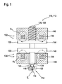
- hydraulic valves 110 which can be used in fuel injectors 112 used. Other parts of the fuel injectors 112 are not shown in the figures.
- the hydraulic valves 110 can be used in an injector housing, not shown, of the fuel injector 112, in which, for example, an injection valve member can be stored.
- the hydraulic valves 110 each have a valve region 114 with a valve seat 116 and a valve bore 118. Valve seat 116 and valve bore 118 may be formed, for example, in an injector body 120, which is shown only in a rudimentary manner.
- the valve bore 118 may, for example, open directly or indirectly in a control chamber of the fuel injector 112, via which a stroke of an injection valve member is controllable.
- the hydraulic valve 110 has a closing element 122 in the valve region 114, which in the illustrated exemplary embodiment is configured by way of example as a ball.
- a closing element 122 in the valve region 114 which in the illustrated exemplary embodiment is configured by way of example as a ball.
- another embodiment is in principle possible, for example, a configuration as a cone, as a cone, as a spherical cap or in a similar manner.
- the hydraulic valve 110 configured, for example, as a ball valve and / or has such a ball valve.
- the closing element 122 is connected to an actuator 124, via which the closing element 122 can be pressed or lifted off in its valve seat 116.
- the actuator 124 is exemplified in the illustrated embodiment as a cylindrical actuator 124 in the form of an actuator rod. However, other embodiments are possible in principle.
- This hydraulic force counteracts a spring force of a spring element 126 in the form of a closing spring 128.
- This closing spring 128 is supported at its lower end directly on the actuator 124 or indirectly on this, for example an armature 130, which may be connected to the actuator 124.
- This armature is part of two magnetic actuators 132, 134, of which a first magnetic actuator 132 is designed as an opening magnetic actuator and a second magnetic actuator 134 in this embodiment as a closing magnetic actuator.
- the magnetic actuators 132, 134 each comprise a first magnetic coil 136 and a second magnetic coil 138 and a first magnetic core 140 and a second magnetic core 142, respectively.
- the magnetic actuators 132, 134 differ in the exemplary embodiments according to FIGS Figures 1 to 4B in terms of the design of their magnetic cores 140, 142 and in terms of the design and arrangement of their armature 130. This will be explained in more detail below.
- the first magnetic actuator 132 is configured to generate a magnetic flux ⁇ o
- the second magnetic actuator 134 is configured to generate a magnetic flux ⁇ c .
- These magnetic fluxes ⁇ o and ⁇ c are indicated in the figures by closed, circular arrows.
- FIG. 1 an embodiment of a hydraulic valve 110 is shown, which actively closes and in which the magnetic actuators 132, 234 are designed separately, so that the two magnetic circuits of these magnetic actuators 132, 134 substantially or not affect magnetically substantially.
- the first magnetic actuator 132 has a first armature 144 and the second magnetic actuator 134 has a second armature 146. Both armatures 144, 146 are connected to the actuator 124 and are arranged substantially parallel to one another.
- the magnetic cores 140, 142 of the two magnetic actuators 132, 134 are formed separately from each other in this embodiment.
- FIGS. 2A to 4B exemplary embodiments are shown in which the first magnetic actuator 132 and the second magnetic actuator 134 influence one another, in particular in that their magnetic fluxes ⁇ o and ⁇ c overlap one another or influence one another.
- These embodiments have the advantage that stored in the magnetic fields energies of the other magnetic actuator 132, 134 can be shared.
- the polarization of the other magnetic circuit can be shared in the construction of the magnetic flux of the own magnetic circuit, resulting in a lower energy consumption for the magnetic field structure. This can be done in different ways.
- the magnetic cores 114, 142 may be designed at least partially component-identical, so that the magnetic fluxes ⁇ o and ⁇ c can overlap.
- a common anchor can also be used. Since in the shared part, that is, for example, in the shared armature 130 and / or in the shared magnetic core 140, 142, the magnetic flux direction is maintained and thus the flux density does not change so much, eddy currents are also reduced in this part. In the case of opposing flows, on the other hand, the flux build-up of one magnetic circuit can be used for the flow reduction of the other magnetic circuit.
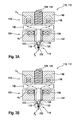
- FIGS. 2A and 2B For example, an embodiment of a hydraulic valve 110 is shown in which a common armature 130 is used.
- the magnetic coils 136, 138 and the magnetic cores 140, 142 of the magnetic actuators 132, 134 are disposed on opposite sides of this shared armature 130.
- FIG. 2A an embodiment in which the magnetic fluxes ⁇ o and ⁇ c within the armature 130 are in the same direction, whereas in the embodiment in FIG. 2B these magnetic fluxes ⁇ o and ⁇ c are configured in opposite directions. Accordingly, in FIG.
- FIGS. 3A and 3B an embodiment of a hydraulic valve 110 is shown, which initially substantially the embodiment according to the FIGS. 2A and 2B equivalent.
- a common armature 130 is used for the two magnetic actuators 132, 134.
- the second magnetic core 142 does not completely surround the second magnetic coil 138.
- the actuator 124 and / or a part of the armature 130 can thus at least partially take on the role of the magnetic cores 140, 142 in this and also in other embodiments.
- the armature 130 can be used as the inner pole of the closing magnetic circuit of the second magnetic actuator 134, so that a part of the magnetic flux ⁇ c passes through this armature 130 and / or the actuator 124.
- the embodiment in the FIGS. 3A and 3B essentially the embodiment according to the FIGS. 2A or 2B. Again in is FIG. 3A an equal magnetic flux is shown, whereas in FIG. 3B an opposite magnetic flux is shown.
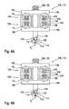
- FIGS. 4A and 4B Embodiments are shown in which the magnetic actuators 132, 134 have separate armatures 144, 146, similar to FIG. 1 , However, in this embodiment, the armatures 144, 146 on opposite sides with respect to the magnetic cores 140, 142 are arranged. Accordingly, in contrast to the other embodiments, in the illustrated embodiment according to the FIGS. 4A and 4B the magnetic actuator 132, 134 preferably share the magnetic cores 140, 142 as the common magnetic cores 148. Accordingly, the magnetic fluxes ⁇ o and ⁇ c can be superimposed again , Analogous to the FIGS. 2A and 2B or 3A and 3B is in FIG. 4A again shown an arrangement in which the magnetic fluxes ⁇ o and ⁇ c are configured in the same direction in the common magnetic core 148, whereas in the embodiment according to FIG. 4B are designed in opposite directions.
- the closing spring 128 can be designed to be comparatively small and / or provided with a smaller preload, as a result of which a magnetic power requirement, in particular for the opening magnetic actuators 132, can be reduced.
- the armature 130 can be made smaller.
- the closing spring 128 may serve as a return spring in all embodiments and may generate an additional acceleration force for closing the fuel injector 112. As a result, a simpler operation of the fuel injector 112 is possible up to a limit rail pressure.
- the hydraulic valve 110 can close automatically.
- existing fuel injectors 112 may also be modified. Particular advantages are offered by the hydraulic valve 110 for a high operating pressure (rail pressure) with simultaneous need for very short switching times.
Landscapes
- Engineering & Computer Science (AREA)
- Chemical & Material Sciences (AREA)
- Combustion & Propulsion (AREA)
- Mechanical Engineering (AREA)
- General Engineering & Computer Science (AREA)
- Physics & Mathematics (AREA)
- Electromagnetism (AREA)
- Magnetically Actuated Valves (AREA)
- Fuel-Injection Apparatus (AREA)
Applications Claiming Priority (1)
| Application Number | Priority Date | Filing Date | Title |
|---|---|---|---|
| DE200910003219 DE102009003219A1 (de) | 2009-05-19 | 2009-05-19 | Aktiv schließendes Magnetventil für Magnetinjektoren |
Publications (2)
| Publication Number | Publication Date |
|---|---|
| EP2256333A1 true EP2256333A1 (fr) | 2010-12-01 |
| EP2256333B1 EP2256333B1 (fr) | 2015-02-18 |
Family
ID=42562611
Family Applications (1)
| Application Number | Title | Priority Date | Filing Date |
|---|---|---|---|
| EP20100157971 Active EP2256333B1 (fr) | 2009-05-19 | 2010-03-26 | Soupape magnétique à fermeture active pour injecteurs magnétiques |
Country Status (3)
| Country | Link |
|---|---|
| EP (1) | EP2256333B1 (fr) |
| CN (1) | CN101892930B (fr) |
| DE (1) | DE102009003219A1 (fr) |
Families Citing this family (4)
| Publication number | Priority date | Publication date | Assignee | Title |
|---|---|---|---|---|
| DE102012219657A1 (de) | 2012-10-26 | 2014-04-30 | Robert Bosch Gmbh | Kraftstoffinjektor |
| DE102015203415B4 (de) | 2015-02-26 | 2020-11-26 | Schaeffler Technologies AG & Co. KG | Verfahren zur Simulation extremer oder defekter Magnetventile zur Demonstration der Ausfalleffekte und Fehlererkennung für die Zertifizierung eines Fahrzeug-Diagnose-Systems |
| DE102017201581A1 (de) * | 2017-02-01 | 2018-08-02 | Robert Bosch Gmbh | Magnetventilanordnung für einen Kraftstoffinjektor zum Einspritzen von flüssigem und/oder gasförmigem Kraftstoff |
| PL426295A1 (pl) | 2018-07-10 | 2020-01-13 | Prosperitos Spółka Z Ograniczoną Odpowiedzialnością | Sposób zasilania parą wodną o parametrach ultra-nadkrytycznych tłokowych silników parowych i zawór do zasilania parą wodną o parametrach ultra-nadkrytycznych tłokowych silników parowych |
Citations (7)
| Publication number | Priority date | Publication date | Assignee | Title |
|---|---|---|---|---|
| JPH0783146A (ja) * | 1993-09-13 | 1995-03-28 | Aisin Seiki Co Ltd | 燃料噴射装置 |
| EP0987431A2 (fr) * | 1998-09-18 | 2000-03-22 | Lucas Industries Limited | Injecteur de carburant |
| US6065684A (en) * | 1998-03-27 | 2000-05-23 | General Motors Corporation | Fuel injector and method |
| EP1035322A2 (fr) * | 1999-03-09 | 2000-09-13 | Delphi Technologies, Inc. | Injecteur de combustible |
| WO2001057390A1 (fr) * | 2000-02-04 | 2001-08-09 | Robert Bosch Gmbh | Soupape d'injection de carburant et procede pour faire fonctionner cette derniere |
| EP1533517A2 (fr) * | 2003-11-14 | 2005-05-25 | Magneti Marelli Powertrain S.p.A. | Injecteur de carburant avec aiguille à actionnement hydraulique |
| JP2005344636A (ja) * | 2004-06-03 | 2005-12-15 | Toyota Motor Corp | デリバリパイプの電磁リリーフ弁 |
-
2009
- 2009-05-19 DE DE200910003219 patent/DE102009003219A1/de not_active Withdrawn
-
2010
- 2010-03-26 EP EP20100157971 patent/EP2256333B1/fr active Active
- 2010-05-19 CN CN201010185369.6A patent/CN101892930B/zh active Active
Patent Citations (7)
| Publication number | Priority date | Publication date | Assignee | Title |
|---|---|---|---|---|
| JPH0783146A (ja) * | 1993-09-13 | 1995-03-28 | Aisin Seiki Co Ltd | 燃料噴射装置 |
| US6065684A (en) * | 1998-03-27 | 2000-05-23 | General Motors Corporation | Fuel injector and method |
| EP0987431A2 (fr) * | 1998-09-18 | 2000-03-22 | Lucas Industries Limited | Injecteur de carburant |
| EP1035322A2 (fr) * | 1999-03-09 | 2000-09-13 | Delphi Technologies, Inc. | Injecteur de combustible |
| WO2001057390A1 (fr) * | 2000-02-04 | 2001-08-09 | Robert Bosch Gmbh | Soupape d'injection de carburant et procede pour faire fonctionner cette derniere |
| EP1533517A2 (fr) * | 2003-11-14 | 2005-05-25 | Magneti Marelli Powertrain S.p.A. | Injecteur de carburant avec aiguille à actionnement hydraulique |
| JP2005344636A (ja) * | 2004-06-03 | 2005-12-15 | Toyota Motor Corp | デリバリパイプの電磁リリーフ弁 |
Also Published As
| Publication number | Publication date |
|---|---|
| DE102009003219A1 (de) | 2010-11-25 |
| CN101892930A (zh) | 2010-11-24 |
| EP2256333B1 (fr) | 2015-02-18 |
| CN101892930B (zh) | 2016-09-14 |
Similar Documents
| Publication | Publication Date | Title |
|---|---|---|
| EP2634413B1 (fr) | Injecteur | |
| EP3409984B1 (fr) | Distributeur à tiroir cylindrique | |
| EP3478957B1 (fr) | Soupape d'injection d'un carburant gazeux | |
| DE19708104A1 (de) | Magnetventil | |
| DE102013106214A1 (de) | Kolbenschieberventil | |
| EP3102863B1 (fr) | Soupape électromagnétique et système de refroidissement de moteur à combustion interne équipé d'une soupape électromagnétique | |
| EP1882122B1 (fr) | Valve, notamment valve proportionnelle de limitation de pression | |
| EP2256333B1 (fr) | Soupape magnétique à fermeture active pour injecteurs magnétiques | |
| EP2914842B1 (fr) | Actionneur | |
| DE102008032133A1 (de) | Kraftstoffeinspritzvorrichtung | |
| EP3364015B1 (fr) | Soupape de commutation électromagnétique et pompe haute pression à carburant | |
| DE102014220877B3 (de) | Kraftstoffeinspritzventil | |
| WO2021156083A1 (fr) | Dispositif de réservoir pour le stockage d'un milieu gazeux | |
| EP2711595A1 (fr) | Dispositif de soupape à deux sièges | |
| DE102016220912A1 (de) | Kraftstoffeinspritzventil | |
| DE4403148C2 (de) | Elektromagnetisch ansteuerbares Mehrstrahleinspritzventil, insbesondere für Verbrennungsmotoren mit zwei Ansaugkanälen pro Zylinder | |
| EP3545185B1 (fr) | Valve de dosage de gaz | |
| EP3394420B1 (fr) | Électrovalve pour une soupape d'injection de carburant, procédé de fonctionnement de l'électrovalve et soupape d'injection de carburant comprenant une telle électrovalve | |
| DE102008040068B4 (de) | Konkave Luftspaltbegrenzung bei Magnetventil | |
| EP2469140B1 (fr) | Soupape | |
| DE102013210881A1 (de) | Elektromagnetisch ansteuerbares Saugventil für eine Hochdruckpumpe | |
| DE19936943A1 (de) | Brennstoffeinspritzventil | |
| WO2011069759A1 (fr) | Mécanisme électromagnétique pour une vanne | |
| EP3361085B1 (fr) | Soupape de commutation électromagnétique et pompe haute pression à carburant | |
| DE102009027103A1 (de) | Ventilmodul mit fest eingestelltem Ankerhub |
Legal Events
| Date | Code | Title | Description |
|---|---|---|---|
| PUAI | Public reference made under article 153(3) epc to a published international application that has entered the european phase |
Free format text: ORIGINAL CODE: 0009012 |
|
| AK | Designated contracting states |
Kind code of ref document: A1 Designated state(s): AT BE BG CH CY CZ DE DK EE ES FI FR GB GR HR HU IE IS IT LI LT LU LV MC MK MT NL NO PL PT RO SE SI SK SM TR |
|
| AX | Request for extension of the european patent |
Extension state: AL BA ME RS |
|
| 17P | Request for examination filed |
Effective date: 20110601 |
|
| 17Q | First examination report despatched |
Effective date: 20111206 |
|
| GRAP | Despatch of communication of intention to grant a patent |
Free format text: ORIGINAL CODE: EPIDOSNIGR1 |
|
| INTG | Intention to grant announced |
Effective date: 20141111 |
|
| GRAS | Grant fee paid |
Free format text: ORIGINAL CODE: EPIDOSNIGR3 |
|
| GRAA | (expected) grant |
Free format text: ORIGINAL CODE: 0009210 |
|
| AK | Designated contracting states |
Kind code of ref document: B1 Designated state(s): AT BE BG CH CY CZ DE DK EE ES FI FR GB GR HR HU IE IS IT LI LT LU LV MC MK MT NL NO PL PT RO SE SI SK SM TR |
|
| REG | Reference to a national code |
Ref country code: GB Ref legal event code: FG4D Free format text: NOT ENGLISH |
|
| REG | Reference to a national code |
Ref country code: CH Ref legal event code: EP |
|
| REG | Reference to a national code |
Ref country code: AT Ref legal event code: REF Ref document number: 710779 Country of ref document: AT Kind code of ref document: T Effective date: 20150315 |
|
| REG | Reference to a national code |
Ref country code: IE Ref legal event code: FG4D Free format text: LANGUAGE OF EP DOCUMENT: GERMAN |
|
| REG | Reference to a national code |
Ref country code: DE Ref legal event code: R096 Ref document number: 502010008894 Country of ref document: DE Effective date: 20150402 |
|
| REG | Reference to a national code |
Ref country code: NL Ref legal event code: VDEP Effective date: 20150218 |
|
| REG | Reference to a national code |
Ref country code: LT Ref legal event code: MG4D |
|
| PG25 | Lapsed in a contracting state [announced via postgrant information from national office to epo] |
Ref country code: HR Free format text: LAPSE BECAUSE OF FAILURE TO SUBMIT A TRANSLATION OF THE DESCRIPTION OR TO PAY THE FEE WITHIN THE PRESCRIBED TIME-LIMIT Effective date: 20150218 Ref country code: SE Free format text: LAPSE BECAUSE OF FAILURE TO SUBMIT A TRANSLATION OF THE DESCRIPTION OR TO PAY THE FEE WITHIN THE PRESCRIBED TIME-LIMIT Effective date: 20150218 Ref country code: FI Free format text: LAPSE BECAUSE OF FAILURE TO SUBMIT A TRANSLATION OF THE DESCRIPTION OR TO PAY THE FEE WITHIN THE PRESCRIBED TIME-LIMIT Effective date: 20150218 Ref country code: LT Free format text: LAPSE BECAUSE OF FAILURE TO SUBMIT A TRANSLATION OF THE DESCRIPTION OR TO PAY THE FEE WITHIN THE PRESCRIBED TIME-LIMIT Effective date: 20150218 Ref country code: ES Free format text: LAPSE BECAUSE OF FAILURE TO SUBMIT A TRANSLATION OF THE DESCRIPTION OR TO PAY THE FEE WITHIN THE PRESCRIBED TIME-LIMIT Effective date: 20150218 Ref country code: NO Free format text: LAPSE BECAUSE OF FAILURE TO SUBMIT A TRANSLATION OF THE DESCRIPTION OR TO PAY THE FEE WITHIN THE PRESCRIBED TIME-LIMIT Effective date: 20150518 |
|
| PG25 | Lapsed in a contracting state [announced via postgrant information from national office to epo] |
Ref country code: NL Free format text: LAPSE BECAUSE OF FAILURE TO SUBMIT A TRANSLATION OF THE DESCRIPTION OR TO PAY THE FEE WITHIN THE PRESCRIBED TIME-LIMIT Effective date: 20150218 Ref country code: GR Free format text: LAPSE BECAUSE OF FAILURE TO SUBMIT A TRANSLATION OF THE DESCRIPTION OR TO PAY THE FEE WITHIN THE PRESCRIBED TIME-LIMIT Effective date: 20150519 Ref country code: IS Free format text: LAPSE BECAUSE OF FAILURE TO SUBMIT A TRANSLATION OF THE DESCRIPTION OR TO PAY THE FEE WITHIN THE PRESCRIBED TIME-LIMIT Effective date: 20150618 Ref country code: LV Free format text: LAPSE BECAUSE OF FAILURE TO SUBMIT A TRANSLATION OF THE DESCRIPTION OR TO PAY THE FEE WITHIN THE PRESCRIBED TIME-LIMIT Effective date: 20150218 |
|
| PG25 | Lapsed in a contracting state [announced via postgrant information from national office to epo] |
Ref country code: DK Free format text: LAPSE BECAUSE OF FAILURE TO SUBMIT A TRANSLATION OF THE DESCRIPTION OR TO PAY THE FEE WITHIN THE PRESCRIBED TIME-LIMIT Effective date: 20150218 Ref country code: CZ Free format text: LAPSE BECAUSE OF FAILURE TO SUBMIT A TRANSLATION OF THE DESCRIPTION OR TO PAY THE FEE WITHIN THE PRESCRIBED TIME-LIMIT Effective date: 20150218 Ref country code: EE Free format text: LAPSE BECAUSE OF FAILURE TO SUBMIT A TRANSLATION OF THE DESCRIPTION OR TO PAY THE FEE WITHIN THE PRESCRIBED TIME-LIMIT Effective date: 20150218 Ref country code: RO Free format text: LAPSE BECAUSE OF FAILURE TO SUBMIT A TRANSLATION OF THE DESCRIPTION OR TO PAY THE FEE WITHIN THE PRESCRIBED TIME-LIMIT Effective date: 20150218 Ref country code: SK Free format text: LAPSE BECAUSE OF FAILURE TO SUBMIT A TRANSLATION OF THE DESCRIPTION OR TO PAY THE FEE WITHIN THE PRESCRIBED TIME-LIMIT Effective date: 20150218 |
|
| REG | Reference to a national code |
Ref country code: CH Ref legal event code: PL |
|
| REG | Reference to a national code |
Ref country code: DE Ref legal event code: R097 Ref document number: 502010008894 Country of ref document: DE |
|
| PG25 | Lapsed in a contracting state [announced via postgrant information from national office to epo] |
Ref country code: MC Free format text: LAPSE BECAUSE OF FAILURE TO SUBMIT A TRANSLATION OF THE DESCRIPTION OR TO PAY THE FEE WITHIN THE PRESCRIBED TIME-LIMIT Effective date: 20150218 Ref country code: PL Free format text: LAPSE BECAUSE OF FAILURE TO SUBMIT A TRANSLATION OF THE DESCRIPTION OR TO PAY THE FEE WITHIN THE PRESCRIBED TIME-LIMIT Effective date: 20150218 |
|
| PLBE | No opposition filed within time limit |
Free format text: ORIGINAL CODE: 0009261 |
|
| STAA | Information on the status of an ep patent application or granted ep patent |
Free format text: STATUS: NO OPPOSITION FILED WITHIN TIME LIMIT |
|
| REG | Reference to a national code |
Ref country code: IE Ref legal event code: MM4A |
|
| 26N | No opposition filed |
Effective date: 20151119 |
|
| PG25 | Lapsed in a contracting state [announced via postgrant information from national office to epo] |
Ref country code: LI Free format text: LAPSE BECAUSE OF NON-PAYMENT OF DUE FEES Effective date: 20150331 Ref country code: CH Free format text: LAPSE BECAUSE OF NON-PAYMENT OF DUE FEES Effective date: 20150331 Ref country code: IE Free format text: LAPSE BECAUSE OF NON-PAYMENT OF DUE FEES Effective date: 20150326 |
|
| PG25 | Lapsed in a contracting state [announced via postgrant information from national office to epo] |
Ref country code: SI Free format text: LAPSE BECAUSE OF FAILURE TO SUBMIT A TRANSLATION OF THE DESCRIPTION OR TO PAY THE FEE WITHIN THE PRESCRIBED TIME-LIMIT Effective date: 20150218 |
|
| REG | Reference to a national code |
Ref country code: FR Ref legal event code: PLFP Year of fee payment: 7 |
|
| REG | Reference to a national code |
Ref country code: AT Ref legal event code: MM01 Ref document number: 710779 Country of ref document: AT Kind code of ref document: T Effective date: 20150326 |
|
| PG25 | Lapsed in a contracting state [announced via postgrant information from national office to epo] |
Ref country code: AT Free format text: LAPSE BECAUSE OF NON-PAYMENT OF DUE FEES Effective date: 20150326 |
|
| PG25 | Lapsed in a contracting state [announced via postgrant information from national office to epo] |
Ref country code: MT Free format text: LAPSE BECAUSE OF FAILURE TO SUBMIT A TRANSLATION OF THE DESCRIPTION OR TO PAY THE FEE WITHIN THE PRESCRIBED TIME-LIMIT Effective date: 20150218 |
|
| REG | Reference to a national code |
Ref country code: FR Ref legal event code: PLFP Year of fee payment: 8 |
|
| PG25 | Lapsed in a contracting state [announced via postgrant information from national office to epo] |
Ref country code: HU Free format text: LAPSE BECAUSE OF FAILURE TO SUBMIT A TRANSLATION OF THE DESCRIPTION OR TO PAY THE FEE WITHIN THE PRESCRIBED TIME-LIMIT; INVALID AB INITIO Effective date: 20100326 Ref country code: BG Free format text: LAPSE BECAUSE OF FAILURE TO SUBMIT A TRANSLATION OF THE DESCRIPTION OR TO PAY THE FEE WITHIN THE PRESCRIBED TIME-LIMIT Effective date: 20150218 Ref country code: SM Free format text: LAPSE BECAUSE OF FAILURE TO SUBMIT A TRANSLATION OF THE DESCRIPTION OR TO PAY THE FEE WITHIN THE PRESCRIBED TIME-LIMIT Effective date: 20150218 |
|
| PG25 | Lapsed in a contracting state [announced via postgrant information from national office to epo] |
Ref country code: CY Free format text: LAPSE BECAUSE OF FAILURE TO SUBMIT A TRANSLATION OF THE DESCRIPTION OR TO PAY THE FEE WITHIN THE PRESCRIBED TIME-LIMIT Effective date: 20150218 |
|
| PG25 | Lapsed in a contracting state [announced via postgrant information from national office to epo] |
Ref country code: BE Free format text: LAPSE BECAUSE OF NON-PAYMENT OF DUE FEES Effective date: 20150331 Ref country code: PT Free format text: LAPSE BECAUSE OF FAILURE TO SUBMIT A TRANSLATION OF THE DESCRIPTION OR TO PAY THE FEE WITHIN THE PRESCRIBED TIME-LIMIT Effective date: 20150618 |
|
| PG25 | Lapsed in a contracting state [announced via postgrant information from national office to epo] |
Ref country code: TR Free format text: LAPSE BECAUSE OF FAILURE TO SUBMIT A TRANSLATION OF THE DESCRIPTION OR TO PAY THE FEE WITHIN THE PRESCRIBED TIME-LIMIT Effective date: 20150218 |
|
| PG25 | Lapsed in a contracting state [announced via postgrant information from national office to epo] |
Ref country code: LU Free format text: LAPSE BECAUSE OF NON-PAYMENT OF DUE FEES Effective date: 20150326 |
|
| REG | Reference to a national code |
Ref country code: FR Ref legal event code: PLFP Year of fee payment: 9 |
|
| PG25 | Lapsed in a contracting state [announced via postgrant information from national office to epo] |
Ref country code: MK Free format text: LAPSE BECAUSE OF FAILURE TO SUBMIT A TRANSLATION OF THE DESCRIPTION OR TO PAY THE FEE WITHIN THE PRESCRIBED TIME-LIMIT Effective date: 20150218 |
|
| PGFP | Annual fee paid to national office [announced via postgrant information from national office to epo] |
Ref country code: FR Payment date: 20250324 Year of fee payment: 16 |
|
| PGFP | Annual fee paid to national office [announced via postgrant information from national office to epo] |
Ref country code: GB Payment date: 20250324 Year of fee payment: 16 |
|
| PGFP | Annual fee paid to national office [announced via postgrant information from national office to epo] |
Ref country code: DE Payment date: 20250522 Year of fee payment: 16 |
|
| PGFP | Annual fee paid to national office [announced via postgrant information from national office to epo] |
Ref country code: IT Payment date: 20250331 Year of fee payment: 16 |