EP2256384A2 - Vanne d'étranglement pour matières liquides et/ou gazeuses - Google Patents
Vanne d'étranglement pour matières liquides et/ou gazeuses Download PDFInfo
- Publication number
- EP2256384A2 EP2256384A2 EP10163408A EP10163408A EP2256384A2 EP 2256384 A2 EP2256384 A2 EP 2256384A2 EP 10163408 A EP10163408 A EP 10163408A EP 10163408 A EP10163408 A EP 10163408A EP 2256384 A2 EP2256384 A2 EP 2256384A2
- Authority
- EP
- European Patent Office
- Prior art keywords
- valve
- throttle
- opening
- throttle valve
- valve opening
- Prior art date
- Legal status (The legal status is an assumption and is not a legal conclusion. Google has not performed a legal analysis and makes no representation as to the accuracy of the status listed.)
- Withdrawn
Links
- 239000000126 substance Substances 0.000 title claims description 6
- 239000012530 fluid Substances 0.000 title 1
- 229920000642 polymer Polymers 0.000 claims abstract description 9
- 239000002184 metal Substances 0.000 claims abstract description 5
- 239000007788 liquid Substances 0.000 claims description 4
- 230000001105 regulatory effect Effects 0.000 claims description 2
- 230000033228 biological regulation Effects 0.000 description 3
- 230000001276 controlling effect Effects 0.000 description 2
- 238000004519 manufacturing process Methods 0.000 description 2
- 239000000463 material Substances 0.000 description 2
- 230000007423 decrease Effects 0.000 description 1
- 238000010586 diagram Methods 0.000 description 1
- 238000006073 displacement reaction Methods 0.000 description 1
- 238000005516 engineering process Methods 0.000 description 1
- 239000000446 fuel Substances 0.000 description 1
- 238000002347 injection Methods 0.000 description 1
- 239000007924 injection Substances 0.000 description 1
- 210000004072 lung Anatomy 0.000 description 1
- 239000011295 pitch Substances 0.000 description 1
- 239000000047 product Substances 0.000 description 1
- 239000000523 sample Substances 0.000 description 1
- 239000013589 supplement Substances 0.000 description 1
- 238000011144 upstream manufacturing Methods 0.000 description 1
Images

Classifications
-
- F—MECHANICAL ENGINEERING; LIGHTING; HEATING; WEAPONS; BLASTING
- F16—ENGINEERING ELEMENTS AND UNITS; GENERAL MEASURES FOR PRODUCING AND MAINTAINING EFFECTIVE FUNCTIONING OF MACHINES OR INSTALLATIONS; THERMAL INSULATION IN GENERAL
- F16K—VALVES; TAPS; COCKS; ACTUATING-FLOATS; DEVICES FOR VENTING OR AERATING
- F16K31/00—Actuating devices; Operating means; Releasing devices
- F16K31/004—Actuating devices; Operating means; Releasing devices actuated by piezoelectric means
-
- F—MECHANICAL ENGINEERING; LIGHTING; HEATING; WEAPONS; BLASTING
- F02—COMBUSTION ENGINES; HOT-GAS OR COMBUSTION-PRODUCT ENGINE PLANTS
- F02M—SUPPLYING COMBUSTION ENGINES IN GENERAL WITH COMBUSTIBLE MIXTURES OR CONSTITUENTS THEREOF
- F02M63/00—Other fuel-injection apparatus having pertinent characteristics not provided for in groups F02M39/00 - F02M57/00 or F02M67/00; Details, component parts, or accessories of fuel-injection apparatus, not provided for in, or of interest apart from, the apparatus of groups F02M39/00 - F02M61/00 or F02M67/00; Combination of fuel pump with other devices, e.g. lubricating oil pump
- F02M63/0012—Valves
- F02M63/0031—Valves characterized by the type of valves, e.g. special valve member details, valve seat details, valve housing details
- F02M63/004—Sliding valves, e.g. spool valves, i.e. whereby the closing member has a sliding movement along a seat for opening and closing
-
- F—MECHANICAL ENGINEERING; LIGHTING; HEATING; WEAPONS; BLASTING
- F02—COMBUSTION ENGINES; HOT-GAS OR COMBUSTION-PRODUCT ENGINE PLANTS
- F02M—SUPPLYING COMBUSTION ENGINES IN GENERAL WITH COMBUSTIBLE MIXTURES OR CONSTITUENTS THEREOF
- F02M63/00—Other fuel-injection apparatus having pertinent characteristics not provided for in groups F02M39/00 - F02M57/00 or F02M67/00; Details, component parts, or accessories of fuel-injection apparatus, not provided for in, or of interest apart from, the apparatus of groups F02M39/00 - F02M61/00 or F02M67/00; Combination of fuel pump with other devices, e.g. lubricating oil pump
- F02M63/0012—Valves
- F02M63/0059—Arrangements of valve actuators
- F02M63/0063—Two or more actuators acting on a single valve body
-
- F—MECHANICAL ENGINEERING; LIGHTING; HEATING; WEAPONS; BLASTING
- F02—COMBUSTION ENGINES; HOT-GAS OR COMBUSTION-PRODUCT ENGINE PLANTS
- F02M—SUPPLYING COMBUSTION ENGINES IN GENERAL WITH COMBUSTIBLE MIXTURES OR CONSTITUENTS THEREOF
- F02M63/00—Other fuel-injection apparatus having pertinent characteristics not provided for in groups F02M39/00 - F02M57/00 or F02M67/00; Details, component parts, or accessories of fuel-injection apparatus, not provided for in, or of interest apart from, the apparatus of groups F02M39/00 - F02M61/00 or F02M67/00; Combination of fuel pump with other devices, e.g. lubricating oil pump
- F02M63/0012—Valves
- F02M63/0059—Arrangements of valve actuators
- F02M63/0064—Two or more actuators acting on two or more valve bodies
-
- F—MECHANICAL ENGINEERING; LIGHTING; HEATING; WEAPONS; BLASTING
- F02—COMBUSTION ENGINES; HOT-GAS OR COMBUSTION-PRODUCT ENGINE PLANTS
- F02M—SUPPLYING COMBUSTION ENGINES IN GENERAL WITH COMBUSTIBLE MIXTURES OR CONSTITUENTS THEREOF
- F02M63/00—Other fuel-injection apparatus having pertinent characteristics not provided for in groups F02M39/00 - F02M57/00 or F02M67/00; Details, component parts, or accessories of fuel-injection apparatus, not provided for in, or of interest apart from, the apparatus of groups F02M39/00 - F02M61/00 or F02M67/00; Combination of fuel pump with other devices, e.g. lubricating oil pump
- F02M63/0012—Valves
- F02M63/0059—Arrangements of valve actuators
- F02M63/0066—Combination of electromagnetic and piezoelectric or magnetostrictive actuators
-
- F—MECHANICAL ENGINEERING; LIGHTING; HEATING; WEAPONS; BLASTING
- F16—ENGINEERING ELEMENTS AND UNITS; GENERAL MEASURES FOR PRODUCING AND MAINTAINING EFFECTIVE FUNCTIONING OF MACHINES OR INSTALLATIONS; THERMAL INSULATION IN GENERAL
- F16K—VALVES; TAPS; COCKS; ACTUATING-FLOATS; DEVICES FOR VENTING OR AERATING
- F16K3/00—Gate valves or sliding valves, i.e. cut-off apparatus with closing members having a sliding movement along the seat for opening and closing
- F16K3/02—Gate valves or sliding valves, i.e. cut-off apparatus with closing members having a sliding movement along the seat for opening and closing with flat sealing faces; Packings therefor
- F16K3/0254—Gate valves or sliding valves, i.e. cut-off apparatus with closing members having a sliding movement along the seat for opening and closing with flat sealing faces; Packings therefor being operated by particular means
-
- F—MECHANICAL ENGINEERING; LIGHTING; HEATING; WEAPONS; BLASTING
- F16—ENGINEERING ELEMENTS AND UNITS; GENERAL MEASURES FOR PRODUCING AND MAINTAINING EFFECTIVE FUNCTIONING OF MACHINES OR INSTALLATIONS; THERMAL INSULATION IN GENERAL
- F16K—VALVES; TAPS; COCKS; ACTUATING-FLOATS; DEVICES FOR VENTING OR AERATING
- F16K3/00—Gate valves or sliding valves, i.e. cut-off apparatus with closing members having a sliding movement along the seat for opening and closing
- F16K3/30—Details
- F16K3/34—Arrangements for modifying the way in which the rate of flow varies during the actuation of the valve
Definitions
- the invention relates to a throttle valve for liquid and / or gaseous substances, with at least one valve element for releasing or closing a valve opening and with at least one valve actuator displacing the piezoelectric actuator.
- Throttle valves of the type mentioned are known.
- throttle valves are known in which a displaceable by a piezo actuator valve element in the form of a valve needle opens or closes a valve opening by the valve needle is displaced coaxially to the valve opening or in the direction of the material flow through the valve opening, and thereby the Volume or mass flow determined by the released valve opening and the pressures in front of and behind the valve opening.
- Corresponding throttle valves are also known for gaseous substances.
- the valve element for releasing or closing the valve opening at least substantially transversely to the valve opening, or in other words transversely to the substantial material flow through the valve opening is displaced.
- the closing and opening movement of the valve element take place substantially orthogonally or perpendicular to the volume flowing substantially through the valve opening.
- the throttle valve can be produced inexpensively and, on the other hand, a particularly precise adjustment of the pressures in front of and behind the valve opening and of the volume flowing through the valve opening can be ensured in this manner.
- the valve element is thereby moved transversely across the valve opening by means of the piezo actuator.
- the valve element is designed as a flat valve plate. This is preferably on a flat surface of a guide wall, in which the valve opening is formed. This ensures a tight closure of the valve opening.
- the valve plate is at least substantially made of metal. This ensures sufficient stability of the throttle valve and a corresponding lifetime.
- the throttle valve advantageously has further guide means for the valve plate, so that it is displaceable on a specific path by means of the piezo actuator to ensure precise adjustment.
- the guide means are formed as the valve opening having guide walls, between which rests the valve plate.
- the valve plate is thus preferably slidably mounted between at least two guide walls. Additional guide walls can additionally serve laterally to the valve plate as guide walls of the valve plate for guidance.
- the valve opening is formed.
- Each of the opposite guide walls, between which the valve plate is displaceable has for this purpose an opening, wherein the openings are expediently arranged coaxially to each other. Together, the openings form the valve opening of the throttle valve.
- the guide side walls of the throttle valve close the space between the guide walls to the side, so that flowing through the opening of a liquid or gaseous Substance also completely out through the other opening again and no volume or mass losses occur.
- valve plate By displacing the valve plate between the guide walls, which have or form the valve opening, high pressure differences between the areas before (high pressure area) and behind (low pressure area) of the valve opening - seen in the flow direction - can be realized or adjusted by means of the piezo actuator by means of the throttle valve ,
- At least one of the guide walls has a polymer layer assigned to the valve plate.
- at least the guide wall has a polymer layer assigned to the valve plate, against which the valve plate is pressed due to the pressure difference.
- the combination of polymer layer and metallic valve plate allows a particularly low-friction relative movement between the two elements, whereby the wear is reduced.
- the polymer layer increases the tightness of the throttle valve.
- the valve opening - seen in the direction of movement of the valve element - a constant width.
- the valve opening for example, square or rectangular in shape and aligned according to the direction of movement of the valve plate or the valve element.
- the width of the valve opening - seen in the direction of movement of the valve element - varies. This makes it possible in a particularly simple manner to obtain a greater latitude for different pressure differences / flow volume. If the valve opening is, for example, triangular in shape and aligned in such a way that the width of the valve opening decreases when closing (ie in the closing movement direction of the valve element), small volume flows or high pressure differences can be set particularly precisely, a coarse adjustment being made by the further opening of the throttle valve.
- the configuration of the valve opening can also be formed exactly mirrored to the above-described. It is also conceivable, of course, a discontinuous Weitenver selectedung the valve opening over its longitudinal extent.
- the piezo actuator is assigned a second actuator, in particular a magnetic actuator, which serves to displace the piezoactuator.
- a second actuator in particular a magnetic actuator
- the valve element can not only be displaced over a wider range, but in particular also shorten the setting time, so that the setting of the throttle valve can be quickly and precisely adapted to the requirements, even on a fast time scale.
- the magnet actuator forms a particularly suitable means in this regard.
- other actuators pneumatic, hydraulic and / or electric motor
- the throttle valve has a second valve element for releasing or closing the valve opening.
- the valve element can be designed as described above.
- the second valve element is arranged opposite to the first valve element, so that it closes the valve opening coming from the other / opposite side.
- the second valve element displacing the piezo actuator, a second actuator, in particular a second solenoid actuator can be assigned. If the width of the valve opening-seen in the direction of movement of the valve element or in its longitudinal extent-varies, this results in a multiplicity of possible settings which can be set quickly and precisely by means of the two valve elements and the associated piezoactuators.
- the throttle valve has at least one sensor for regulating the position of the valve element as a function of a pressure detected by the sensor, in particular in a low-pressure region of the valve.
- the cross-sectional area of the valve opening is selected such that with minimal pressure in the high-pressure region of the throttle valve, a maximum required volume flow is ensured by the completely released valve opening.
- the cross-sectional area of the valve opening should correspond to the area which supplies the maximum required mass flow at a minimum pressure in the high-pressure region of the throttle valve, for example at a minimum tank pressure. As a result, an adequate supply is guaranteed at all times.
- the FIG. 1 shows a schematic representation of a first embodiment of an advantageous throttle valve 1 for liquid and / or gaseous substances.
- the throttle valve 1 has a high-pressure region 2 and a low-pressure region 3, which can be connected to one another by means of a valve opening 4.
- the valve opening 4 is formed as two coaxially arranged openings 14, 15 which are formed in two the high pressure region 2 of the Neider réelle Scheme 3 separating walls.
- the walls 5 and 6 are advantageously at least substantially made of metal and serve here as guide walls 9 and 10.
- the valve element 7 and the valve plate 8 is also at least substantially made of metal and displaceable by a piezoelectric actuator 11.
- the piezoelectric actuator 11 is fixedly arranged between the walls 5 and 6.
- the guide walls 9 and 10 each have a polymer layer 12 or 13 on their side facing the valve element or the valve plate 8.
- the polymer layers 12 and 13 ensure the tightness of the throttle valve 1 and reduce the friction between the valve plate 8 and the guide walls 9 and 10th
- valve opening 4 By controlling the piezoelectric actuator 11, the valve opening 4 can now be released or closed.
- the valve element 7 transversely to the valve opening 4 By moving the valve element 7 transversely to the valve opening 4 only small actuating forces for the piezo actuator are required, which also smaller response times are available, so that can be responded to a change in demand particularly quickly.
- the displacement transversely to the valve opening 4 also results in that noise is reduced or low in comparison with known throttle valves, in which the valve element is moved in the direction of the volume / mass flow.
- the so-designed throttle valve 1 is particularly robust.
- the valve element 8 is held firmly between the guide walls 9 and 10. An unintentional opening due to an excessive pressure difference can not be done, for example.
- FIG. 2 shows a schematic plan view of the throttle valve 1 from the FIG. 1 , wherein here only the valve opening 4, the valve element 7 and the piezo-actuator 11 are shown.
- the FIG. 2 shows a particularly advantageous embodiment of the throttle valve 1, in which the width of the valve opening 4 over its longitudinal extension, ie seen in the direction of movement of the valve element 7 and the valve plate 8 varies.
- the valve opening 4 is given a shape in which the opening width does not vary constantly with the manipulated value.
- the throttle or cross-sectional area of the valve opening 4 is just the integral of the opening width along the travel and can thus realize any functions.
- the mass flow can be finely adjusted with small opening widths, coarser with larger opening widths.
- the valve opening has a wedge-shaped or triangular cross-section, which is aligned in the direction of movement of the valve element 7.
- the cross-sectional shape of the openings 14, 15 of course corresponds to the cross-sectional shape of the valve opening 4.
- the cross-sectional area of the valve port 4 by a different magnitude changed.
- the direction of movement of the valve element 7 and the valve plate 8 is indicated by a double arrow 17.
- the cross-sectional shape of the valve surface 4 can be arbitrary, the requirements be selected accordingly.
- the cross-sectional area varies discontinuously over the longitudinal extent of the valve opening 4 and, for example, has a step shape for this purpose.
- circular and / or elliptical valve openings are conceivable.
- a variable mass flow or volume flow permanently flows from the low-pressure region 3, for example.
- the throttle valve 1 has the task of keeping the pressure in the low-pressure region 3 at a constant value.
- a corresponding pressure sensor in the low-pressure region 3 is advantageously provided.
- the sensor is expediently electrically connected to the piezoelectric actuator 11 so that a particularly fast control or adjustment of the throttle valve 1 can take place.
- the valve opening 4 has a cross-sectional area, which is chosen such that even at minimum pressure in the high-pressure region 2, a maximum required mass or volume flow is ensured by the valve opening 4.
- the positioning of the valve plate 8 is effected by the piezoelectric actuator 11 in the fixed direction.
- the guide walls 9 and 10 also guide side walls - not shown here - provided.
- the guide side walls advantageously have a polymer layer to ensure the tightness and to reduce friction.
- the throttle valve 1 may have any outer contour.
- a correspondingly shaped wall 16 forms the outside of the throttle valve. 1
- the mass flow / volume flow released through the valve opening 4 is proportional to the product of pressure difference and throttle area.
- the released cross-sectional area of the valve opening 4 must be able to vary over three to four orders of magnitude.
- the throttle valve described above allows such a setting within a very short time (about 1 ms).
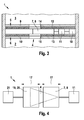
- the FIG. 3 shows an expanded embodiment of the throttle valve 1 of the FIG. 1 .
- the throttle valve 1 of the FIG. 3 in addition to the piezoelectric actuator 11, a further actuator 18 which is assigned to the piezoelectric actuator 11 and connected upstream.
- the actuator 18 is advantageously designed for larger pitches than the piezoelectric actuator 11 in order to increase the actuating speed of the throttle valve 1 substantially.
- the actuator 18 is designed as a magnetic actuator. This causes in operation a coarse regulation of the opening width of the valve opening 4 on a fast time scale.
- the more precise piezo actuator 11, on the other hand, is responsible for the fine regulation. In principle, it is conceivable to carry out the control of the two actuators 11 and 18 both via a characteristic diagram and via a feedback with measuring probes.
- FIG. 4 shows in a further schematic plan view of the throttle valve 1, an advantageous development, both as a supplement to the embodiment of FIG. 1 as well as to the FIG. 3 can be provided.
- the representation corresponds to the representation of the FIG. 2 , It differs only in that a second valve element 19, designed as a valve plate 20, is provided.
- the valve plate 20 is also slidably mounted between the guide walls 9 and 10 and the guide side walls, not shown.
- the valve plate 20 is also associated with a corresponding second piezoelectric actuator 21, which serves for displacing or controlling the valve plate 20.
- the piezo actuators 11 and 21 and the valve plates 8 and 20 are arranged such that the valve plates 8 and 20 are displaceable / movable on the same axis and thereby lie opposite each other in mirror image.
- the valve opening 4 can be influenced simultaneously from two sides or the released cross section can be adjusted.
- the valve opening 4 itself is in turn wedge-shaped, as described above, formed. Of course, other cross-sectional shapes are also conceivable here.
- one of the valve plates 8, 20 serves to define an "operating point", that is, a reference opening width for the throttle area or for the released cross-sectional area of the valve opening 4.
- the desired throttle area or released cross-sectional area of the valve opening 4 is set.
- the thus formed throttle valve 1 allows in a simple manner numerous adjustment options for the mass or volume flow. In particular, this design allows rapid adjustment of the desired throttle area.
- both piezo actuators 11 and 21 are each a magnetic actuator - according to the embodiment of FIG. 3 - Assigned to ensure an even faster adjustment of the throttle area.
- the advantageous throttle valve 1 in each of the described embodiments allows a quick and precise adjustment of the desired throttle area.
- the throttle valve 1 in this case has a sensor which is arranged in the low-pressure region 3, so that a particularly fast precise regulation of the throttle surface can take place.
- the throttle valve 1 it is possible to manufacture this space-optimized and cost-efficient. In addition, it has high tightness and ruggedness, and can also be used in noise-sensitive applications.
Landscapes
- Engineering & Computer Science (AREA)
- General Engineering & Computer Science (AREA)
- Mechanical Engineering (AREA)
- Chemical & Material Sciences (AREA)
- Combustion & Propulsion (AREA)
- Physics & Mathematics (AREA)
- Electromagnetism (AREA)
- Electrically Driven Valve-Operating Means (AREA)
Applications Claiming Priority (1)
| Application Number | Priority Date | Filing Date | Title |
|---|---|---|---|
| DE200910026554 DE102009026554A1 (de) | 2009-05-28 | 2009-05-28 | Drosselventil für flüssige und/oder gasförmige Stoffe |
Publications (2)
| Publication Number | Publication Date |
|---|---|
| EP2256384A2 true EP2256384A2 (fr) | 2010-12-01 |
| EP2256384A3 EP2256384A3 (fr) | 2014-07-16 |
Family
ID=42670527
Family Applications (1)
| Application Number | Title | Priority Date | Filing Date |
|---|---|---|---|
| EP10163408.7A Withdrawn EP2256384A3 (fr) | 2009-05-28 | 2010-05-20 | Vanne d'étranglement pour matières liquides et/ou gazeuses |
Country Status (2)
| Country | Link |
|---|---|
| EP (1) | EP2256384A3 (fr) |
| DE (1) | DE102009026554A1 (fr) |
Families Citing this family (2)
| Publication number | Priority date | Publication date | Assignee | Title |
|---|---|---|---|---|
| CN102537389B (zh) | 2007-12-11 | 2014-06-11 | 等熵有限公司 | 阀 |
| DE102011078074A1 (de) | 2011-06-24 | 2012-12-27 | Robert Bosch Gmbh | Drossel |
Family Cites Families (10)
| Publication number | Priority date | Publication date | Assignee | Title |
|---|---|---|---|---|
| JP2532907Y2 (ja) * | 1992-02-10 | 1997-04-16 | 動力炉・核燃料開発事業団 | 幅広パルスノズル |
| DE19621796A1 (de) * | 1996-05-30 | 1997-12-04 | Nass Magnet Gmbh | Ventil |
| DE19702259C1 (de) * | 1997-01-23 | 1998-02-05 | Temic Bayern Chem Airbag Gmbh | Gasgenerator |
| GB9811398D0 (en) * | 1998-05-27 | 1998-07-22 | Pbt Limited | Spool valve |
| DE19939446A1 (de) * | 1999-08-20 | 2001-03-01 | Bosch Gmbh Robert | Kraftstoffeinspritzvorrichtung für Brennkraftmaschinen |
| US20070075286A1 (en) * | 2005-10-04 | 2007-04-05 | Par Technologies, Llc | Piezoelectric valves drive |
| DE102006036781A1 (de) * | 2006-08-07 | 2008-02-14 | Robert Bosch Gmbh | Injektor und zugehöriges Betriebsverfahren |
| CN101568754B (zh) * | 2006-12-28 | 2011-05-25 | 株式会社富士金 | 带入口节流槽的微小流量控制装置的设计方法 |
| DE102007027961B3 (de) * | 2007-06-19 | 2008-07-24 | Staiger Gmbh & Co. Kg | Ventil |
| US7849870B2 (en) * | 2007-11-01 | 2010-12-14 | Honeywell International Inc. | Piezoelectric pressure control valve |
-
2009
- 2009-05-28 DE DE200910026554 patent/DE102009026554A1/de not_active Withdrawn
-
2010
- 2010-05-20 EP EP10163408.7A patent/EP2256384A3/fr not_active Withdrawn
Non-Patent Citations (1)
| Title |
|---|
| None |
Also Published As
| Publication number | Publication date |
|---|---|
| EP2256384A3 (fr) | 2014-07-16 |
| DE102009026554A1 (de) | 2010-12-02 |
Similar Documents
| Publication | Publication Date | Title |
|---|---|---|
| EP3280905B1 (fr) | Soupape d'injection de gaz pour contrôler un flux de fluide | |
| DE102005031411A1 (de) | Verfahren zur Steuerung eines zwischen zwei Vakuumkammern angeordneten Vakuumventils | |
| EP2425159A1 (fr) | Vanne papillon proportionnelle | |
| DE112009001550T5 (de) | Vorspannfeder mit verteilter Steifigkeit für ein Aktorsystem und Kraftstoffinjektor mit derselben | |
| WO2013017352A1 (fr) | Soupape de régulation de pression électromagnétique pour la commande de composants commandés par pression dans le domaine automobile | |
| DE102008032133B4 (de) | Kraftstoffeinspritzvorrichtung | |
| EP3368775B1 (fr) | Dispositif de commande d'écoulement de fluide et procédé pour faire fonctionner un dispositif de commande d'écoulement de fluide | |
| WO2001095045A1 (fr) | Systeme pneumatique de regulation de pression | |
| EP2792889A1 (fr) | Ensemble de vanne régulatrice de débit | |
| EP3414482B1 (fr) | Distributeur proportionnel | |
| DE102015121047A1 (de) | Ventilantrieb mit Stellungssensor | |
| EP2256384A2 (fr) | Vanne d'étranglement pour matières liquides et/ou gazeuses | |
| DE102009057992A1 (de) | Vorrichtung zur Ansteuerung eines doppelwirkenden Hydraulikkolbens einer Spritzgießmaschine | |
| DE10123157C1 (de) | Pneumatikventil | |
| EP1537337B1 (fr) | Dispositif de servocommande hautement dynamique a soupapes | |
| DE4117445C2 (de) | Ventil zum Steuern oder Regeln des Durchflusses eines Strömungsmittels | |
| DE3836076A1 (de) | Steuerteil fuer ein steuersystem zur steuerung des inneren volumens eines rotationskompressors | |
| EP3293599A1 (fr) | Vanne de réduction de pression | |
| EP3043114B1 (fr) | Soupape de regulation | |
| DE3739824A1 (de) | Vorgesteuertes 3-wege-druckregelventil | |
| WO2006005290A1 (fr) | Soupape de commande electrohydraulique | |
| EP0825349B1 (fr) | Valve de commande directionnelle et proportionnelle | |
| DE102012005543B4 (de) | Druckregelvorrichtung | |
| EP1614947A1 (fr) | Vanne électro-hydraulique | |
| EP3457011A1 (fr) | Régulateur de débit |
Legal Events
| Date | Code | Title | Description |
|---|---|---|---|
| PUAI | Public reference made under article 153(3) epc to a published international application that has entered the european phase |
Free format text: ORIGINAL CODE: 0009012 |
|
| AK | Designated contracting states |
Kind code of ref document: A2 Designated state(s): AL AT BE BG CH CY CZ DE DK EE ES FI FR GB GR HR HU IE IS IT LI LT LU LV MC MK MT NL NO PL PT RO SE SI SK SM TR |
|
| AX | Request for extension of the european patent |
Extension state: BA ME RS |
|
| PUAL | Search report despatched |
Free format text: ORIGINAL CODE: 0009013 |
|
| AK | Designated contracting states |
Kind code of ref document: A3 Designated state(s): AL AT BE BG CH CY CZ DE DK EE ES FI FR GB GR HR HU IE IS IT LI LT LU LV MC MK MT NL NO PL PT RO SE SI SK SM TR |
|
| AX | Request for extension of the european patent |
Extension state: BA ME RS |
|
| RIC1 | Information provided on ipc code assigned before grant |
Ipc: F16K 31/00 20060101ALI20140606BHEP Ipc: F02M 63/00 20060101ALI20140606BHEP Ipc: F16K 3/34 20060101ALI20140606BHEP Ipc: F16K 3/02 20060101AFI20140606BHEP |
|
| STAA | Information on the status of an ep patent application or granted ep patent |
Free format text: STATUS: THE APPLICATION IS DEEMED TO BE WITHDRAWN |
|
| 18D | Application deemed to be withdrawn |
Effective date: 20150117 |