EP2256405A2 - Chaudière pour générateur électrique basée sur une chaudière externe avec un rendement amélioré - Google Patents
Chaudière pour générateur électrique basée sur une chaudière externe avec un rendement amélioré Download PDFInfo
- Publication number
- EP2256405A2 EP2256405A2 EP09163632A EP09163632A EP2256405A2 EP 2256405 A2 EP2256405 A2 EP 2256405A2 EP 09163632 A EP09163632 A EP 09163632A EP 09163632 A EP09163632 A EP 09163632A EP 2256405 A2 EP2256405 A2 EP 2256405A2
- Authority
- EP
- European Patent Office
- Prior art keywords
- ducts
- boiler
- furnace
- combustion
- initial
- Prior art date
- Legal status (The legal status is an assumption and is not a legal conclusion. Google has not performed a legal analysis and makes no representation as to the accuracy of the status listed.)
- Withdrawn
Links
Images


Classifications
-
- F—MECHANICAL ENGINEERING; LIGHTING; HEATING; WEAPONS; BLASTING
- F22—STEAM GENERATION
- F22B—METHODS OF STEAM GENERATION; STEAM BOILERS
- F22B7/00—Steam boilers of furnace-tube type, i.e. the combustion of fuel being performed inside one or more furnace tubes built-in in the boiler body
- F22B7/04—Steam boilers of furnace-tube type, i.e. the combustion of fuel being performed inside one or more furnace tubes built-in in the boiler body with auxiliary water tubes
-
- F—MECHANICAL ENGINEERING; LIGHTING; HEATING; WEAPONS; BLASTING
- F22—STEAM GENERATION
- F22B—METHODS OF STEAM GENERATION; STEAM BOILERS
- F22B7/00—Steam boilers of furnace-tube type, i.e. the combustion of fuel being performed inside one or more furnace tubes built-in in the boiler body
- F22B7/04—Steam boilers of furnace-tube type, i.e. the combustion of fuel being performed inside one or more furnace tubes built-in in the boiler body with auxiliary water tubes
- F22B7/06—Steam boilers of furnace-tube type, i.e. the combustion of fuel being performed inside one or more furnace tubes built-in in the boiler body with auxiliary water tubes inside the furnace tube in transverse arrangements
-
- F—MECHANICAL ENGINEERING; LIGHTING; HEATING; WEAPONS; BLASTING
- F22—STEAM GENERATION
- F22B—METHODS OF STEAM GENERATION; STEAM BOILERS
- F22B7/00—Steam boilers of furnace-tube type, i.e. the combustion of fuel being performed inside one or more furnace tubes built-in in the boiler body
- F22B7/04—Steam boilers of furnace-tube type, i.e. the combustion of fuel being performed inside one or more furnace tubes built-in in the boiler body with auxiliary water tubes
- F22B7/08—Steam boilers of furnace-tube type, i.e. the combustion of fuel being performed inside one or more furnace tubes built-in in the boiler body with auxiliary water tubes inside the furnace tube in longitudinal arrangement
Definitions
- the solution according to an embodiment of the present invention generally relates to the field of the generation of energy. More specifically, this solution relates to the boilers for electrical generators.
- a typical example is an installation for generating electrical energy of the turbo-compressor type.
- a compressor compresses a gas (such as air); the compressed air is mixed to a fuel and made to bum in a combustion chamber, so as to increase its temperature, speed and volume.
- the air is then directed towards a gas turbine (at Joule cycle) so as to generate mechanical energy, which in turn is exploited for generating electrical energy.
- the residual heat of the air being output by the turbine is generally recovered for pre-heating the air; moreover, such residual heat can also be used to produce thermal energy in a co-generation installation.
- the combustion occurs in a distinct boiler (which replaces the normal combustion chamber between the compressor and the turbine).
- the air being used by the turbine is not subject to the combustion process (so that corresponding cleaning operations are not required); the air is instead heated in a heat exchanger that is inserted in the boiler (where another gas is burnt).
- the heat exchanger is formed by a spiral-like duct that extends vertically; in this way, it is possible to make the duct with a large length (so as to obtain a sufficient heat exchange) but with a limited size.
- this causes remarkable losses of pressure that reduce the useful power of the air.
- the boiler can use different types of fuel.
- renewable sources consists of the biomasses (such as pellets), which consist of a material of organic origin (of the vegetable or animal type, but not of the fossil type) whose exploitation time is comparable to the regeneration one.
- biomasses such as pellets
- the technologies available for exploiting the biomasses are rather complex, so that they are hard to apply in installations of small size.
- the solution according to an embodiment of the present invention is based on the idea of partitioning the flow of the air (or of any other process flow) in the heat exchanger of the boiler.
- an aspect of the solution according to an embodiment of the invention proposes a boiler for an electrical generator of the external-boiler type (for example, a gas micro-turbine).
- the boiler includes a furnace for producing heat through combustion of a fuel (for example, a biomass).
- the boiler is provided with an input for receiving a process fluid (for example, air).
- a heat exchanger causes the process fluid to flow close to the furnace (so that it is heated by the heat produced by the furnace).
- the boiler is also provided with an output for supplying the heated process fluid to the electrical generator.
- the heat exchanger includes a plurality of ducts being connected in parallel between the input and the output (for partitioning the flow of the process fluid); the ducts are arranged as a tunnel around the furnace along a flow direction of combustion smokes being produced by the furnace.
- the ducts include at least one initial duct being connected to the input, the at least one initial duct being arranged longitudinally along the flow direction at a first side of the furnace, at least one lateral duct being arranged longitudinally along the flow direction at a second side of the furnace opposite the first side, at least one group of a plurality of initial bridge ducts, the initial bridge ducts of each group being connected in parallel between a corresponding initial duct and a corresponding lateral duct, at least one final duct being connected to the output, the at least one final duct being arranged longitudinally downstream the at least one initial duct along the flow direction at the first side of the furnace, and at least one group of a plurality of final bridge ducts, the final bridge ducts of each group being connected in parallel between a corresponding lateral duct and a corresponding final duct.
- each final duct is queued to a corresponding initial duct, the at least one lateral duct having a length substantially equal to said queuing.
- the at least one initial duct, lateral duct, group of initial bridge ducts, final duct, and group of final bridge ducts consist of a plurality of initial ducts, lateral ducts, groups of initial bridge ducts, final ducts, and groups of final bridge ducts, respectively.
- the groups of initial bridge ducts are interleaved to each other, and/or the groups of final bridge ducts are interleaved to each other.
- the furnace is arranged in an initial portion of the heat exchanger along the flow direction, the boiler further including deflecting means for deflecting the combustion smokes towards the tunnel-arranged ducts.
- the deflecting means includes a barrier for the combustion smokes being arranged within an ending portion of the initial bridge ducts along the flow direction.
- the barrier includes a wall having a shape corresponding to a shape of the initial bridge ducts and a height lower than a height of the initial bridge ducts.
- the boiler includes a further heat exchanger for heating a combustion gas to be supplied to the furnace by exploiting the combustion smokes, the further heat exchanger being arranged downstream the heat exchanger along the flow direction.
- the further heat exchanger includes at least one further input for receiving the combustion gas, at least one further output for supplying the heated combustion gas to the furnace, and at least one group of a plurality of transversal ducts extending transversally to the flow direction, the transversal ducts of each group being connected in parallel between a corresponding further input and a corresponding further output for partitioning a flow of the combustion gas.
- the at least one further input, further output, and group of transversal ducts include a first, a second and a third further inputs, further outputs, and groups of transversal ducts, the first further output being adapted to supply the heated combustion gas in a central region of the furnace, the second further output being adapted to supply the heated combustion gas in an upper region of the furnace with respect to the combustion, and the third further output being adapted to supply the heated combustion gas downstream the furnace along the flow direction.
- the transversal ducts of each group are arranged parallel to each other in at least one plan being substantially perpendicular to the flow direction.
- the transversal ducts of at least one group are arranged in a number of plans higher than a number of plans of a preceding group of transversal ducts along the flow direction.
- the boiler includes further deflecting means for deflecting the combustion smokes towards the further heat exchanger.
- the further deflecting means includes a further barrier for the combustion smokes being arranged within a terminal portion of the tunnel-arranged ducts of the heat exchanger along the flow direction.
- the further barrier includes a cusp-shaped further wall being turned towards the flow direction.
- Another aspect of the solution according to an embodiment of the invention proposes a heat exchanger for use in such boiler.
- a further aspect of the solution according to an embodiment of the invention proposes an energy generation installation including an electrical generator and such boiler for supplying the heated process fluid to the electrical generator.
- the installation further includes means for adding at least part of the process fluid being exhausted by the electrical generator to a combustion gas to be supplied to the boiler.
- the electrical generator is a gas turbine
- the installation further including a compressor for compressing the process fluid to be supplied to the boiler, and a cooling exchanger for cooling the process fluid to be supplied to the compressor by exploiting the combustion smokes being exhausted by the boiler and/or at least part of the process fluid being exhausted by the electrical generator.
- the installation is a co-generation installation of thermal energy and electrical energy, the installation further including thermal conversion means, and means for supplying the combustion smokes being exhausted by the boiler and/or at least part of the process fluid being exhausted by the electrical generator to the conversion means.
- the fuel is a biomass.
- a different aspect of the solution according to an embodiment of the invention proposes a corresponding method.
- a method for generating energy by means of an electrical generator of the external-boiler type including the steps of: generating heat through combustion of a fuel in a furnace of the boiler, receiving a process fluid at an input of the boiler, causing the process fluid to flow close to the furnace by means of a heat exchanger, the process fluid being heated by the heat produced by the furnace, and supplying the heated process fluid to the electrical generator from an output of the boiler, wherein the step of causing the process fluid to flow close to the furnace includes partitioning the flow of the process fluid by means of a plurality of ducts of the heat exchanger being connected in parallel between the input and the output, the ducts being arranged as a tunnel around the furnace along a flow direction of combustion smokes being produced by the furnace.
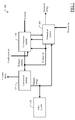
- the installation 100 includes an electrical energy generation system 105 (for example, being based on micro-turbine), which sucks process air (or thermo-vector) from the external environment.
- process air or thermo-vector
- the process air is compressed and supplied from the generation system 105 to a combustion system 110 being fed by biomass.
- the combustion system 110 burns the biomass by using combustion air, which is sucked from the external environment with the recovery of part of the exhaust air being output by the generation system 105; such combustion process generates heat that heats the process air; the process air so heated is returned from the combustion system 110 to the generation system 105 for producing electrical energy, which is supplied to an external electrical network (not shown in figure).
- Exhaust gases - comprising exhaust smokes from the combustion system 110 with the recovery of the remaining part of the exhaust air from the generation system 105 - are supplied to a thermal conversion system 115.
- the conversion system 115 produces thermal energy by exploiting the exhaust gases, which (once completely exhausted) are then returned to the external environment.
- thermal energy is used by a system of thermal users 120 (either household ones or industrial ones), and it is partially recovered by the generation system 105.
- the generation system 105 is based on a gas micro-turbine 203.
- a suction mouth 206 draws and filters the process air from the external environment.
- the process air is cooled (for example, to 8-12°C) by a cooling device 209 (being supplied by the conversion system 115, as described in the following).
- the process air so cooled is provided to the compressor 212 being supplied by the turbine 203, which compresses it (for example, to 300-400 kPa); in this respect, it should be noted that the previous cooling of the process air remarkably reduces the work being required to the compressor 212 for obtaining the desired pressure of the process air (with a beneficial effect on its yield).
- the compressed process air is then pre-heated (for example, to 450-550°C) by a heat recovery unit 215 that exploits the exhaust air from the turbine 203, so as to increase the overall efficiency of the system 100.
- the (pre-heated) process air is supplied to the combustion system 110.
- the combustion system 110 heats the process air through the combustion of the biomass (for example, by bringing it up to 850-950°C).
- the process air so heated is returned from the combustion system 110 to the turbine 203.
- the process air expands in the turbine 203, thereby acting on corresponding blades that make a shaft of the turbine 203 rotate so as to generate mechanical energy.
- the turbine 203 is connected coaxially to the compressor 212 and to an alternator 218 (for transferring thereto the generated mechanical energy).
- the alternator 218 transforms the received mechanical energy into electric energy in the form of alternating current.
- the alternator 218 is followed by a static alternating current-alternating current (AC-AC) converter 221, which converts the voltage being output by the alternator 218 to a value being compatible with the external electrical network (for example, 50-60 Hz).
- the static converter 221 delivers the electric energy so produced to the electrical network (not shown in the figure) through a corresponding interface 224.
- the generation system 105 and the combustion system 110 are coupled by means of an anchorage system 221, being capable of compensating the different thermal expansions of the two systems 105 and 110.
- a control device 227 (for example, a micro-processor) manages the operation of the generation system 105 and of the combustion system 110. Particularly, the control device 227 manages a starting phase (without using any other conventional fuels) - wherein the combustion system 110 is brought to a working temperature and the turbine 203 is accelerated up to a self-powering speed (by using the alternator 218 in reverse mode as a synchronous starter motor) - and a corresponding stopping phase.
- the control device 227 also manages the supplying of the combustion system 110 so as to reach the desired value of temperature of the process air, in turn determined by a power demand of the system 100. Moreover, the control device 227 detects anomalous operating conditions (for example, overpressure or lack of voltage); in this case, the control device 227 blocks the supplying of the combustion system 110 and actuates a vent valve 230 that discharges the process air into the external environment (so as to cause the safe fast stopping of the turbine 203). The control device 227 may also perform additional functions, such as the management of a parallel with the electrical network, the orchestration of other systems (not shown in the figure), the frequency-power control, the provision of a load island, and the like.
- the exhaust air being output by the turbine 203 (for example, at a temperature of 550-650°C) is used in the recovery unit 215 for pre-heating the process air (to be supplied to the combustion system 110).
- the exhaust air (for example, at a temperature of 450-550°C) is provided to a three-way valve 233, which diverts the exhaust air partially towards the combustion system 110 and partially towards the conversion system 115.
- the combustion system 110 Passing now to the combustion system 110, it is based on a biomass boiler (or combustor) 236; for example, the biomass is of the wooden-cellulose type, such as wood chips, pellets, olive residues, nut residues, corn, woodland cleaning residues, and the like.
- An automatic loading device 239 feeds the biomass to the boiler 236.
- the loading device 239 may be of the hopper, screw or piston type (according to the type of biomass), and it is provided with a shutter for blocking the backfire from the boiler 236.
- the boiler 236 includes a furnace 242, which receives the biomass (from the loading system 239), and burns it by using the combustion air as comburent. Such combustion process generates combustion smokes at high temperature (for example, 950-1,050°C), which combustion smokes are forced by means of a fan (not shown in the figure) along a longitudinal flow direction 245.
- the furnace 242 may be of the fixed grid type (for olive residues or pellets) or of the moving grid type (for heterogeneous material); the furnace 242 further includes a cinerary under the grid (not shown in the figure) for the collection of combustion ashes (which may be extracted either in a manual way or in an automatic way).
- a main air-to-air heat exchanger 248 is used for heating the process air (received from the generation system 105 and to be returned thereto) through the heat being produced by the combustion process (as described in detail in the following).
- the combustion air is sucked from the external environment through an input manifold 251, which splits it into three distinct input ducts (i.e., a primary duct 254a, a secondary duct 254b, and a tertiary duct 254c).
- Three regulation valves 257a, 257b and 257c are inserted along the primary duct 254a, the secondary duct 254b, and the tertiary duct 254c, respectively, for regulating the addition of the exhaust air (of the turbine 203) coming from the three-way valve 233.
- the combustion air (with the addition of part of the exhaust air) is conveyed towards a secondary air-to-air heat exchanger 260 (arranged in the boiler 236 downstream the main heat exchanger 248 along the flow direction 245).
- the secondary heat exchanger 260 pre-heats the combustion air by exploiting the residual heat of the combustion smokes, so as to increase the efficiency of the boiler 236.
- the (pre-heated) combustion air is supplied to the furnace 242 through three distribution ducts, i.e., a primary distribution duct 263a, secondary distribution duct 263b, and a tertiary distribution ducts 263c (for the corresponding ducts 254a, 254b, and 254c), which end with regulation shutters with facing fins.
- the primary duct 263a injects the (primary) combustion air into a central zone of the furnace242
- the secondary duct 263b injects the (secondary) combustion air into an upper zone of the furnace 242
- the tertiary duct 263c injects (tertiary, or post-combustion) combustion air downstream the furnace 242 along the flow direction 245 - so as to optimize the combustion of the biomass.
- An ejector 266 sucks the exhaust smokes being output by the boiler 236 and part of the exhaust air (of the turbine 203) coming from the three-way valve 233.
- the ejector 266 conveys the exhaust smokes and the exhaust air into a single exhaust gases flow (for example, at a temperature of 300-400°C) towards the conversion system 115.
- an air-to-water heat exchanger 269 exploits the residual heat of the exhaust gases to heat water (for example, to a temperature of 80-100°C), by making the exhaust gases pass through a bundle tube being dipped in the water to be heated.
- the (completely exhausted) exhaust gases being output by the heat exchanger 269 are then delivered to the external environment through a chimney 272.
- the warm water so produced is used in a cooling exchanger (chiller) 275 for cooling water (for example, to a temperature of 7-10°C).
- the cold water being produced by the cooling exchanger 275 is supplied to the cooling device 209 for cooling the process air for the compressor 212 (by making it pass through a coil being arranged close to filters for the process air in the suction mouth 206).
- the system of users 120 includes water heating equipments 278 (for example, for household, bath, production use, and the like), which are supplied by the warm water provided by the heat exchanger 275.
- Cooling equipments 281 (for example, for conditioning environments, controlling production processes, and the like) are instead supplied by the cold water being provided by the cooling exchanger 275.
- the exhaust gases (from the ejector 266) may also be used directly by other air heating devices 284 (for example, for heating environments, in drying processes, and the like); particularly, this allows drying the biomass itself being input to the combustion system 110 (so as to increase the efficiency of the combustion process in the boiler 236).
- the system of users 120 may also include electrical energy generators 287 that exploit the warm water being provided by the heat exchanger 269 - for example, being based on the traditional Rankine cycle, on the Organic Rankine Cycle (ORC), and the like.
- FIG.3 there is shown a cross-sectional top view of the boiler 236 according to an embodiment of the invention.
- the boiler 236 is formed by a combustion chamber 305, which is delimited by a base that is closed by a cover being made of steel with multilayer inner covering of insulation panels for high temperatures.
- the combustion chamber 305 is provided with a feeding door 310 of the biomass (being open in a front wall thereof along the flow direction 245, facing the loading device).
- the furnace 242 is made in a hole in the base of the combustion chamber 305, directly downstream the feeding door 310.
- An inlet mouth 315 is made in a sidewall of the cover of the combustion chamber 305 (close to its front wall) for receiving the process air from the generation system, and an outlet mouth 320 is made in a rear wall of the combustion chamber 305 for returning the heated process air to the same generation system.
- the main heat exchanger 248 is connected between the inlet mouth 315 and the outlet mouth 320.
- An initial deflector 325 and a final deflector 330 are arranged within the main heat exchanger 248 (for deflecting the combustion smokes, as it will be apparent in the following of the description).
- the main heat exchanger 248 is followed by the secondary heat exchanger 260.
- the secondary heat exchanger 260 faces an exhaust mouth 335 for the combustion smokes (being made in the rear wall of the combustion chamber 305).
- the input ducts (denoted as a whole with the reference 254) enters the combustion chamber 305 through its rear wall for connecting to the secondary heat exchanger 260; the distribution ducts (denoted as a whole with the reference 263) are in turn connected to the secondary heat exchanger 260 for supplying the pre-heated combustion air to the furnace 242 (not detailed in the figure).
- the main heat exchanger 248 includes a plurality of ducts, which are connected in parallel between the inlet mouth 315 and the outlet mouth 320 for partitioning the flow of the process air; the ducts are arranged as a tunnel around the furnace 242, which tunnel extends along the flow direction 245.
- the proposed solution provides an optimal efficiency of the main heat exchanger 248. Indeed, the splitting of the flow of the process air allows obtaining a high heat exchange surface through the corresponding ducts; at the same time, the connection in parallel of the ducts allows maintaining the path of the process air short, so as to reduce the losses of pressure. Moreover, the tunnel-like shape provides optimal results in terms both of encumbrance and of absorption of the heat produced by the furnace 242.
- the main heat exchanger 248 is made with a canalization of special steel for high temperatures, which is suspended over the base of the combustion chamber. More specifically, an input manifold 405 is connected to the inlet mouth of the combustion chamber for receiving the process air from the generation system, and an output manifold 410 is connected to the outlet mouth of the combustion chamber for returning the heated process air to the same generation system. Two pipes extend longitudinally (along the flow direction) from the input manifold 405 to the output manifold 410; such pipes are abreast, at the side of the furnace (not shown in figure).
- the pipes are closed substantially in the middle by corresponding separation walls, so as to define two initial ducts 415a and 415b (connected to the input manifold 405), and two final ducts 420a and 420b (connected the output manifold 410).
- Two lateral ducts 425a and 425b extend longitudinally as well (with a length substantially equal to the one of the pipes that form the initial ducts 415a, 415b and the final ducts 420a, 420b, and a section substantially equal to the one of them); the lateral ducts 425a and 425b are likewise arranged abreast, at the same height of the initial ducts 415a, 415b and of the final ducts 420a, 420b, but at an opposite side of the furnace.
- a group of initial bridge ducts 430a (for example, 5-15) is connected in parallel between the initial duct 415a and a corresponding portion of the lateral duct 425a; each initial bridge duct 430a is conformed substantially as an arc, and has a reduced section with respect to the one of the ducts 415a,425a according to their number (for example, 1/15-1/5).
- Another group of initial bridge ducts 430b is connected in parallel between the initial duct 415b and a corresponding portion of the lateral duct 425b.
- the initial bridge ducts 430a and 430b are interleaved, and slightly staggered transversally.
- An analogous group of final bridge ducts 435a is connected in parallel between the final duct 420a and a corresponding portion of the lateral duct 425a.
- Another group of final bridge ducts 435b is connected in parallel between the final duct 420b and a corresponding portion of the lateral duct 425b.
- the final bridge ducts 435a and 435b are interleaved, and slightly staggered transversally.
- the input manifold 405 is provided with diverting walls for distributing the process air in the initial ducts 415a and 415b.
- the process air in each initial duct 415a and 415b then splits in the initial bridge ducts 430a and 430b, respectively.
- the process air from the initial bridge ducts 430a and 430b is collected by the lateral ducts 425a and 425b, respectively.
- the process air in each lateral duct 425a and 425b splits again in the final bridge ducts 435a and 435b, respectively.
- the process air from the final bridge ducts 435a and 435b is collected by the final ducts 415a and 415b, respectively.
- the process air from the final ducts 415a and 415b is then conveyed to the output manifold 410.
- the structure described above further improves the efficiency of the main heat exchanger 236.
- the bridge ducts both the initial ones and the final ones
- the bridge ducts being interleaved and staggered to each other provide an optimal heat exchange surface.
- the furnace 242 is arranged in an initial portion of the main heat exchanger 248 (along the flow direction 245); particularly, the furnace 242 ends before the separation walls that define the initial ducts, and then are completely covered by the initial bridge ducts. In such section of the main heat exchanger 248, the heat exchange occurs mostly by radiation. Therefore, the arrangement of the initial bridge ducts (conveying the entire flow of the process air directly over the furnace 248) optimizes the heat exchange in such section.
- the heat exchange occurs mostly by convection.
- the initial deflector 325 is arranged directly downstream the furnace 242 (between the latter and the separation walls that define the initial ducts).
- the initial deflector 325 implements a barrier that deflects the combustion smokes towards the main heat exchanger 248; particularly, in this way the combustion smokes lick the final bridge ducts, wherein the whole flow of the process air is again conveyed.
- the heat exchange in such section of the main heat exchanger 248 as well is optimized.
- the initial deflector 325 is made of a wall of refractory material, which lies on the base of the combustion chamber.
- the initial deflector 325 has a width that is scarcely lower than the encumbrance of the initial bridge ducts 430a, 430b.
- the initial deflector 325 instead has a height that is lower than the one of the initial bridge ducts 430a, 430b; for example, the initial deflector 325 ends with a stepped portion converging inwards, which steps stop at 0,2-0,4 m from the top of the initial bridge ducts 430a, 430b.
- the final deflector 330 is arranged at the end of the main heat exchanger 248 (directly before the secondary heat exchanger 260).
- the final deflector 330 instead deflects the combustion smokes towards the secondary heat exchanger 260.
- the corresponding heat exchange is improved so as to increase the pre-heating of the combustion air (and then the efficiency of the entire boiler).
- the final deflector 330 as well is made of a wall in refractory material, which lies on the base of the combustion chamber 305.
- the final deflector 330 has a width and a height that are slightly lower than the encumbrance of the final bridge ducts.
- the final deflector 330 is formed by two wings, which connect with a cup-like profile (in plan view) being turned towards the flow direction 245.
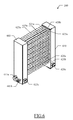
- FIG.6 A perspective representation of the secondary heat exchanger 260 according to an embodiment of the invention is shown in FIG.6 .
- the secondary heat exchanger 260 includes an input tower 605 and an output tower 610, which lies on the base of the combustion chamber.
- the input tower 605 is split into three isolated sections that extend vertically.
- a primary input mouth 615a (on an external sidewall of the input tower 605, down at the back), a secondary input mouth 615b (on the same sidewall of the input tower 605, down in the front), and a tertiary input mouth 615c (on a front wall of the input tower 605, down) are connected to the primary, secondary, and tertiary input ducts, respectively (not shown in the figure).
- the output tower 610 as well is split into three isolated sections that extend vertically.
- a primary output mouth 620a (on an external sidewall of the output tower 610, down at the back), a secondary output mouth 620b (on the same sidewall of the output tower 610, down in the front), and a tertiary output mouth 620c (on a front wall of the output tower 610, down) are connected to the primary, secondary, and tertiary output ducts, respectively (not shown in the figure).
- Primary transversal ducts 625a, secondary transversal ducts 625b, and tertiary transversal ducts 625c are connected in parallel between the sections of the primary 615a-620a, secondary 615b-620b, and tertiary 615c-620c (input and output) mouths, respectively.
- the transversal ducts 625a, 625b, 625c extend transversally to the flow direction; particularly, the transversal ducts 625a, 625b, 625c are arranged (in parallel to each other) in vertical plans being perpendicular to the flow direction (for example, each one including 10-30 transversal ducts 625a, 625b, 625c being stacked one on the other).
- the primary transversal ducts 625a are arranged in three plans in a back region of the secondary heat exchanger 260 (along the flow direction), the secondary transversal ducts 625b are arranged in a single plan in a central region of the secondary heat exchanger 260, and the tertiary transversal ducts 625c as well are arranged in a single plan in a front region of the secondary heat exchanger 260.
- the above-described structure further improves the efficiency of the secondary heat exchanger 260. Particularly, this allows obtaining a substantially uniform distribution of the pre-heating of the combustion air (thanks to the higher number of transversal ducts in the back region being reached to a lower extent by the combustion smokes).
- the boiler has a different structure or includes equivalent components.
- the combustion chamber may have another shape or it may be made of other materials, the input and the output for the process air may be arranged in a different position, the furnace may be shaped in another way, and the like; in any case, the installation may use any other process fluid (such as water).
- the number of ducts described above for partitioning the flow of the process air in the primary heat exchanger is merely indicative, and it does not have to be interpreted in a limitative manner; likewise, nothing prevents arranging the tunnel-like ducts around the furnace with a different shape (for example, rectangular, square, semicircular one).
- the initial deflector is not strictly necessary, and it may also be omitted in a simplified embodiment of the invention.
- the initial deflector with another shape (for example, simply at rectangular cross-section), or with a different size (for example, more narrow, higher and/or lower).
- the proposed embodiment of the secondary heat exchanger with three duct sections (for the primary, secondary and tertiary process air) is not to be intended in a limitative way; indeed, it is possible to distribute the process air in other positions, and provide a different number (either higher or lower, down to a single one) of flows of the process air.
- the transversal ducts may be in a different number, arranged vertically, slanting, and the like.
- transversal ducts in a different number of plans (each one including a different number of transversal ducts) are not excluded; for example, it is possible to have the same number of plans for the different flows of the process air, or even the transversal ducts of two or more flows of the process air (up to all) being arranged in the same plan.
- the final deflector is not strictly necessary, and it may also be omitted in a simplified embodiment of the invention.
- the final deflector with another shape (for example, funnel-like), or with a different size.
- the process air to be supplied to the compressor may be cooled in another way (for example, by exploiting the exhaust smokes from the boiler only or the exhaust gases from the turbine only) - even if such additional feature is not strictly necessary; in any case, there is not excluded the possibility of using electrical generators of other type (for example, with classic gas turbine, steam turbine, and the like).
- thermal users it is possible to provide only some of the thermal users described above, additional thermal users and/or alternatives ones; moreover, nothing prevents supplying such thermal users (or some of them) through the exhaust smokes from the boiler only or the exhaust gases from the turbine only. It should be noted, however, that the application of the proposed solution in an installation for producing electrical energy only (not thermal one) is contemplated.
- biomass consists of any other renewable material (solid, liquid or gas one); in any case, the proposed solution lends itself to be used also in installations that are supplied by other fuels (even conventional ones).
- the same solution may also be implemented with an equivalent method (by using similar steps, removing some steps being non-essential, or adding further optional steps); moreover, the steps may be performed in a different order, concurrently or in an interleaved way (at least in part).
Landscapes
- Engineering & Computer Science (AREA)
- Chemical & Material Sciences (AREA)
- Combustion & Propulsion (AREA)
- Physics & Mathematics (AREA)
- Thermal Sciences (AREA)
- Mechanical Engineering (AREA)
- General Engineering & Computer Science (AREA)
- Air Supply (AREA)
- Control Of Eletrric Generators (AREA)
Applications Claiming Priority (1)
| Application Number | Priority Date | Filing Date | Title |
|---|---|---|---|
| ITMI20081145 ITMI20081145A1 (it) | 2008-06-25 | 2008-06-25 | Caldaia per generatore elettrico a caldaia esterna con migliorata efficienza |
Publications (2)
| Publication Number | Publication Date |
|---|---|
| EP2256405A2 true EP2256405A2 (fr) | 2010-12-01 |
| EP2256405A3 EP2256405A3 (fr) | 2011-03-16 |
Family
ID=40301846
Family Applications (1)
| Application Number | Title | Priority Date | Filing Date |
|---|---|---|---|
| EP09163632A Withdrawn EP2256405A3 (fr) | 2008-06-25 | 2009-06-24 | Chaudière pour générateur électrique basée sur une chaudière externe avec un rendement amélioré |
Country Status (2)
| Country | Link |
|---|---|
| EP (1) | EP2256405A3 (fr) |
| IT (1) | ITMI20081145A1 (fr) |
Cited By (1)
| Publication number | Priority date | Publication date | Assignee | Title |
|---|---|---|---|---|
| CN106352318A (zh) * | 2016-10-11 | 2017-01-25 | 郭志男 | 一种汽态锅炉 |
Family Cites Families (5)
| Publication number | Priority date | Publication date | Assignee | Title |
|---|---|---|---|---|
| GB634750A (en) * | 1947-11-10 | 1950-03-29 | Andre Huet | Improvements in or relating to water tube boilers |
| US3920067A (en) * | 1973-04-11 | 1975-11-18 | Mms Ltd | Heat exchanger for continuous flow fluid heater |
| US4244326A (en) * | 1979-04-12 | 1981-01-13 | Jackson Dennis H | Steam generating system |
| US6644393B2 (en) * | 2002-04-16 | 2003-11-11 | Laars, Inc. | Cylindrical heat exchanger |
| US6718915B1 (en) * | 2002-12-16 | 2004-04-13 | The Babcock & Wilcox Company | Horizontal spiral tube boiler convection pass enclosure design |
-
2008
- 2008-06-25 IT ITMI20081145 patent/ITMI20081145A1/it unknown
-
2009
- 2009-06-24 EP EP09163632A patent/EP2256405A3/fr not_active Withdrawn
Cited By (1)
| Publication number | Priority date | Publication date | Assignee | Title |
|---|---|---|---|---|
| CN106352318A (zh) * | 2016-10-11 | 2017-01-25 | 郭志男 | 一种汽态锅炉 |
Also Published As
| Publication number | Publication date |
|---|---|
| EP2256405A3 (fr) | 2011-03-16 |
| ITMI20081145A1 (it) | 2009-12-26 |
Similar Documents
| Publication | Publication Date | Title |
|---|---|---|
| US12590549B1 (en) | Thermal energy storage system coupled with thermal power cycle systems | |
| CN104654815B (zh) | 马赛克陶瓷窑炉余热发电综合利用系统 | |
| US10247487B2 (en) | Heat exchange unit | |
| US20100062301A1 (en) | System having high-temperature fuel cells | |
| CN102536361A (zh) | 烧结余热与饱和蒸汽综合利用系统 | |
| EP2256405A2 (fr) | Chaudière pour générateur électrique basée sur une chaudière externe avec un rendement amélioré | |
| CN202470789U (zh) | 烧结余热与饱和蒸汽综合利用系统 | |
| CN114909647A (zh) | 用于低负荷稳燃和热电深度解耦的热电联产机组及方法 | |
| CN201488269U (zh) | 模块式燃气热风炉 | |
| CN107270280A (zh) | 循环流化床锅炉及循环流化床联合循环系统 | |
| WO2012004739A2 (fr) | Centrale électrique à biomasse | |
| CN201754033U (zh) | 一种隧道窑烟气余热锅炉 | |
| CN102721075A (zh) | 一种对除尘器内部进行预热的装置和方法 | |
| EP2941556B1 (fr) | Ensemble comprenant une turbine à gaz | |
| CN102536342A (zh) | 纸面石膏板热风炉余热发电工艺 | |
| CN202119091U (zh) | 高效节能热风炉 | |
| CN200996720Y (zh) | 多温区高效常压加热炉 | |
| EP1387994B1 (fr) | Procede de coproduction d'energies thermique et electrique associe a des besoins thermiques de temperature elevees | |
| CN202253554U (zh) | 一种用于火力发电站的锅炉 | |
| CN103486574A (zh) | 大型低一次风功耗超临界循环流化床锅炉 | |
| CN201354688Y (zh) | 生物质炉式冲压燃气涡轮发动机 | |
| CN210219740U (zh) | 一种生物质气化燃烧侧耦合燃煤锅炉 | |
| RO134705A0 (ro) | Instalaţie de cogenerare cu generare de apă caldă pentru încălzirea unei sere | |
| RU2432642C2 (ru) | Система с высокотемпературными топливными элементами | |
| CN102937331A (zh) | 一种双体式锅炉改进结构 |
Legal Events
| Date | Code | Title | Description |
|---|---|---|---|
| PUAI | Public reference made under article 153(3) epc to a published international application that has entered the european phase |
Free format text: ORIGINAL CODE: 0009012 |
|
| AK | Designated contracting states |
Kind code of ref document: A2 Designated state(s): AT BE BG CH CY CZ DE DK EE ES FI FR GB GR HR HU IE IS IT LI LT LU LV MC MK MT NL NO PL PT RO SE SI SK TR |
|
| PUAL | Search report despatched |
Free format text: ORIGINAL CODE: 0009013 |
|
| AK | Designated contracting states |
Kind code of ref document: A3 Designated state(s): AT BE BG CH CY CZ DE DK EE ES FI FR GB GR HR HU IE IS IT LI LT LU LV MC MK MT NL NO PL PT RO SE SI SK TR |
|
| RAP1 | Party data changed (applicant data changed or rights of an application transferred) |
Owner name: TEP TECNOLOGIE PER L'ENERGIA PULITA S.R.L. |
|
| 17P | Request for examination filed |
Effective date: 20110916 |
|
| 17Q | First examination report despatched |
Effective date: 20120629 |
|
| STAA | Information on the status of an ep patent application or granted ep patent |
Free format text: STATUS: THE APPLICATION IS DEEMED TO BE WITHDRAWN |
|
| 18D | Application deemed to be withdrawn |
Effective date: 20130611 |