EP2256457A2 - Mesure de constructions souterraines, notamment lors de l'avancée souterraine, à l'aide de consoles - Google Patents
Mesure de constructions souterraines, notamment lors de l'avancée souterraine, à l'aide de consoles Download PDFInfo
- Publication number
- EP2256457A2 EP2256457A2 EP10005169A EP10005169A EP2256457A2 EP 2256457 A2 EP2256457 A2 EP 2256457A2 EP 10005169 A EP10005169 A EP 10005169A EP 10005169 A EP10005169 A EP 10005169A EP 2256457 A2 EP2256457 A2 EP 2256457A2
- Authority
- EP
- European Patent Office
- Prior art keywords
- measuring
- measurement according
- measurement
- consoles
- prisms
- Prior art date
- Legal status (The legal status is an assumption and is not a legal conclusion. Google has not performed a legal analysis and makes no representation as to the accuracy of the status listed.)
- Granted
Links
- 238000005259 measurement Methods 0.000 title claims description 132
- 238000010276 construction Methods 0.000 claims description 17
- 229910000831 Steel Inorganic materials 0.000 claims description 16
- 239000010959 steel Substances 0.000 claims description 16
- 239000002390 adhesive tape Substances 0.000 claims description 13
- 230000002441 reversible effect Effects 0.000 claims description 13
- 238000012951 Remeasurement Methods 0.000 claims description 7
- 239000000463 material Substances 0.000 claims description 4
- 238000009412 basement excavation Methods 0.000 claims description 2
- 238000000034 method Methods 0.000 abstract description 29
- 230000000295 complement effect Effects 0.000 abstract 1
- 230000005641 tunneling Effects 0.000 description 35
- 239000000853 adhesive Substances 0.000 description 12
- 230000001070 adhesive effect Effects 0.000 description 12
- 230000008569 process Effects 0.000 description 11
- 238000005065 mining Methods 0.000 description 10
- 230000032258 transport Effects 0.000 description 9
- 238000009434 installation Methods 0.000 description 8
- 230000008901 benefit Effects 0.000 description 7
- 238000005520 cutting process Methods 0.000 description 6
- 238000004519 manufacturing process Methods 0.000 description 5
- 238000003825 pressing Methods 0.000 description 4
- 230000005540 biological transmission Effects 0.000 description 3
- 238000005422 blasting Methods 0.000 description 3
- 230000002349 favourable effect Effects 0.000 description 3
- 230000007246 mechanism Effects 0.000 description 3
- 241000238633 Odonata Species 0.000 description 2
- 239000000567 combustion gas Substances 0.000 description 2
- 230000001276 controlling effect Effects 0.000 description 2
- 238000013461 design Methods 0.000 description 2
- 238000003801 milling Methods 0.000 description 2
- 239000002689 soil Substances 0.000 description 2
- 238000010408 sweeping Methods 0.000 description 2
- 230000008685 targeting Effects 0.000 description 2
- NIXOWILDQLNWCW-UHFFFAOYSA-M Acrylate Chemical compound [O-]C(=O)C=C NIXOWILDQLNWCW-UHFFFAOYSA-M 0.000 description 1
- 238000004026 adhesive bonding Methods 0.000 description 1
- 230000015556 catabolic process Effects 0.000 description 1
- 230000008859 change Effects 0.000 description 1
- 230000001427 coherent effect Effects 0.000 description 1
- 238000012790 confirmation Methods 0.000 description 1
- 238000011109 contamination Methods 0.000 description 1
- 238000011161 development Methods 0.000 description 1
- 238000005553 drilling Methods 0.000 description 1
- 239000002360 explosive Substances 0.000 description 1
- 239000003292 glue Substances 0.000 description 1
- 238000009413 insulation Methods 0.000 description 1
- 230000002045 lasting effect Effects 0.000 description 1
- 238000012423 maintenance Methods 0.000 description 1
- 230000003287 optical effect Effects 0.000 description 1
- 230000002093 peripheral effect Effects 0.000 description 1
- 230000010363 phase shift Effects 0.000 description 1
- 239000002984 plastic foam Substances 0.000 description 1
- 229920002635 polyurethane Polymers 0.000 description 1
- 239000004814 polyurethane Substances 0.000 description 1
- 238000002360 preparation method Methods 0.000 description 1
- 238000007639 printing Methods 0.000 description 1
- 230000001105 regulatory effect Effects 0.000 description 1
- 230000002787 reinforcement Effects 0.000 description 1
- 238000007789 sealing Methods 0.000 description 1
- 239000011122 softwood Substances 0.000 description 1
- 238000003892 spreading Methods 0.000 description 1
- 230000007480 spreading Effects 0.000 description 1
- 239000000758 substrate Substances 0.000 description 1
- 210000004127 vitreous body Anatomy 0.000 description 1
Images


Classifications
-
- G—PHYSICS
- G01—MEASURING; TESTING
- G01C—MEASURING DISTANCES, LEVELS OR BEARINGS; SURVEYING; NAVIGATION; GYROSCOPIC INSTRUMENTS; PHOTOGRAMMETRY OR VIDEOGRAMMETRY
- G01C7/00—Tracing profiles
- G01C7/06—Tracing profiles of cavities, e.g. tunnels
-
- E—FIXED CONSTRUCTIONS
- E21—EARTH OR ROCK DRILLING; MINING
- E21D—SHAFTS; TUNNELS; GALLERIES; LARGE UNDERGROUND CHAMBERS
- E21D9/00—Tunnels or galleries, with or without linings; Methods or apparatus for making thereof; Layout of tunnels or galleries
- E21D9/003—Arrangement of measuring or indicating devices for use during driving of tunnels, e.g. for guiding machines
- E21D9/004—Arrangement of measuring or indicating devices for use during driving of tunnels, e.g. for guiding machines using light beams for direction or position control
Definitions
- the invention relates to the measurement of underground structures, in particular in underground propulsion.
- subterranean jacking surveying is essential. But even after completion of an underground structure surveying is necessary to determine, for example, a building work.
- Underground propulsion occurs in mining, in sewer construction, in tunneling, in pipe jacking, underpasses. There are several methods available for underground jacking.
- the building is preferably measured / measured in each direction.
- a cutting tube / cutting shoe is driven through the substrate by means of a tube press. After each press stroke, the press is moved back to the starting position, so that a second piece of pipe in the starting pit can be positioned in front of the press and a renewed pressing operation causes the propulsion of the pipe section and the second pipe section advances the cutting tube.
- the process is repeated with every third piece of pipe as well as with every other piece of pipe.
- the desired planning position of the channel is transferred to the tunneling tools for the sewer construction.
- Tunneling is most similar to tunneling in mining, even though the tunnel cross sections are different than the sections of the track in mining. Tunneling uses the same methods as in mining. Accordingly, an adjustment and remeasurement as in mining also occurs here.
- the pipe jacking is very similar to the tunneling in some areas, especially for larger dimensions. Accordingly, during tunneling, jacking methods such as those used in tunneling or as in sewer construction also occur.
- Underpasses can be tunnel-like, depending on the dimensions. Correspondingly, measurements are then taken as in tunneling.
- the tachymeter is a device with which one can determine horizontal directions, vertical angles and also oblique distances. With it measurements can be carried out quickly and with great accuracy.
- the electronic tachymeters measure the directions after the targeting process automatically. At the same time, electronic distance measurements are carried out. Either the transit time or, in the case of more precise tachymeters, the transit time and phase shift of an emitted and reflected light beam at the target point are measured.
- the light of the carrier wave is in the infrared region or near the infrared region.
- the reflection of the Light beam is usually in a prism, preferably in a retroreflective triple prism or triple mirror.
- the measured values are automatically determined electronically with the modern electronic tachymeters, which can be done by combined / connected computers Depending on the existing programs, a two-dimensional or three-dimensional image of buildings can take place with the electronic tachymeter.
- the latest motorized tachymeters are equipped with an adjustment mechanism and a drive mechanism, which allows the auto-sighting of the triple prism / mirror and a target tracking.
- these tachymeters are programmable so that they can automatically measure several points in precise sequence.
- a triple prism is a vitreous body, which is flat at the front and has three uncoated surfaces at 90 degrees to each other at the back. It reflects the light like a mirror, but much less lossy.
- the clamping is only possible where there are joints with sufficient width, which are able to accommodate the clamping mechanism. This is not only for the joint seal of serious disadvantage.
- the clamping has several other disadvantages.
- the EP1408344 describes a method for geodetic measurement, in which the tunnel wall is measured with laser scanners. At the same time, the distance of the laser scanner from the specific measuring points is measured. This results in the position of the laser scanner. The measured values are then evaluated with a computer.
- a disadvantage of the method is considered that the laser scanner has only a relatively small measuring range. Therefore, a variety of measurements is required. This disadvantage affects the more, ever the distance is longer.
- the DE102005012107 develops the geodetic measurement after the EP 1408344 further. Various, positional points of the laser are measured and set as fixed points.
- the DE3733553 describes a laser-controlled tunneling shield. To determine the position of the shield propulsion is an electrical reflector that emits signals. All values are processed for machine control in a computer.
- the DE 102004010114 describes a measuring method for controlling tunneling machines. A particular difficulty in the curve pressing of pipes is seen because there is no optical lane through the curve. Nevertheless, to perform a laser measurement, a measurement is provided in the manner of a polygonal line.
- the laser should interact with a target board.
- the laser beam forms the desired position of the tunneling machine.
- the target plate is attached to the tunneling machine and the tunneling machine is moved so that the laser beam hits the target field of the target board. Then the tunneling machine has reached its desired position.
- the DE3120010 describes a surveying system for a pre-pressed, curved pipe string.
- a cutting shoe or cutting tube From the pipe string is a cutting shoe or cutting tube.
- To control the cutting shoe while light beams and crosshairs and lasers and receivers and scanning devices are mentioned as prior art.
- a traverse should be measured. Within the traverse the measuring points become and scanning arranged at a fixed predetermined distance.
- the distances of the measuring points remain constant.
- This proposed method prefers light-emitting diodes as measuring points and an ultrasonic measurement.
- the DE69103610 also describes a laser system with reference points.
- the holes In order for the demolition of a predetermined mountain outbreak, the holes should be measured and marked by means of lasers.
- the laser is moved by hand, even if a computer helps with the setting.
- the markings are applied by hand.
- a geodetic laser system should include: a laser measuring unit for performing the distance and angle measurements, a laser projector for directing the laser beam to a breakdown shaft, a control unit for setting the measuring points on the
- the laser measuring unit should work independently of the laser projector.
- the DE 2607280 describes a laser measuring device in which light beams are disassembled and deflected by means of a prism.
- the DE60734622 also describes laser measuring devices for tunneling.
- the laser device is combined with a collimation device.
- Such device is common in lasers to focus the laser beam.
- the use of a prism is provided in this document.
- the latest laser trackers are high-precision measuring instruments that use a combination of angle and distance measurement to capture the 3D point coordinates of an object.
- the Distance measurement is done by laser interferometer or by absolute distance measurement or by a combination of both .
- a laser beam can be generated, which is projected onto the surface to be scanned with a rotating mirror. Due to the rotation mirror, a vast number of measuring points / point cloud are generated.
- the laser beam is reflected by the surface to be measured and, depending on the distance to the surface of the object at different distances on a CCD chip.
- the distances between the laser and the points on the surface of the object are determined by triangulation. Certain contours of the object form as different distances. This data can be used for a subsequent CAD data creation.
- the invention has for its object to provide a more economical
- the invention selects a method as a starting point for the development in which fixed measuring points are created in the underground structure. This does not seem timely in relation to the methods of scanned and computed computers. This means that the invention holds on to the obsolete fixed measuring points. However, the invention goes beyond the prior art in this point by providing adjustable and / or mountable and removable measuring points.
- consoles are removed after completion of the structure.
- the measuring devices include, for example, the devices described above including measuring points, but especially also tachymeters and prisms, as well as gyroscopes for geodetic rangefinding and position determination.
- consoles For a measurement, the consoles should be moved back into the measuring position.
- the adjustment can be achieved by pulling and telescoping the console. Likewise, the adjustment can be achieved by unfolding / folding or swinging / swinging.
- the console is designed in the case as a swivel arm and is swiveled as needed / swung or swung back / pivoted.
- a locking of the adjustable console In the measuring position, a locking of the adjustable console is provided. In the other end position is a locking advantage. It can be used to lock in the measurement position, a clamp or a releasable catch.
- a screw With which the movable part of the console is clamped against the fixed part of the console.
- the screw can engage through a moving slot of the movable console part into a threaded hole of the fixed console part.
- the screw does not end in a screw head, for the one certain tool is required, but in a lever that can be operated without additional tools by hand.
- the movement slot can also be arranged in the fixed part of the console and the threaded hole in the movable part of the console.
- no threaded hole, but only a through hole is provided.
- the screw can cooperate with a nut with which the screw engages behind the corresponding console part (which is otherwise provided with the threaded hole).
- This nut can in turn be designed as a lever so that the nut can be held or moved by hand.
- the screw can also be designed as an anchor screw to engage behind a console part.
- the screw can also completely penetrate the two console parts to be clamped together so that levers for the manual actuation can be arranged at each end.
- console can also be a multiple clamping advantage. This may be the case when the moving part of the console is coarsely played on the fixed part of the console.
- a coarse movement play can be expedient for reasons of production or for reasons of contamination of the console.
- An optional catch allows fast and accurate handling.
- To the detent include a spring-loaded hook and a recess.
- Movable consoles are necessarily multi-part. Then the hook is on one part and the recess for engaging the hook in the other part.
- a preferred embodiment of the consoles provides for the use of U-shaped profiles. Such profiles can form a guide for holding and moving other parts. Other profiles are suitable for the production of such consoles.
- the measuring point in accessible walkways and other accessible underground structures can be brought by means of the console at a distance of 20 to 70 cm from the cavity inner wall, it can also be chosen larger distances, Preferably, the distance is between 30 and 60 cm.
- the spacing ensures freedom of movement for the handling of the measuring devices. Even usual other installations in the underground structures can not interfere with the measurement process with sufficient distance setting.
- the consoles according to the invention may be permanent or temporary fixtures. Other permanent consoles are found particularly in mining and tunneling.
- consoles which are provided for example for the duration of the construction / production of the building.
- consoles which remain in the building for more than one measuring process.
- Other permanent installations include in particular media lines.
- the measuring points are only on one side of the underground structures.
- the measuring points are also on different sides of the building.
- the refraction in the building can be taken into account.
- Refraction refers to the refraction of waves as they pass through media. Depending on the medium, it can lead to significant differences, which are taken into account in geodesy.
- the measuring points can be in the longitudinal direction of the channels and other subterranean structures lie in a straight line or in a different line. This results forcibly, if the measuring points lie on one side only. If at the same time measuring points lie on several sides, then also several measuring points can lie on a common peripheral line of the channel or other underground building.
- the console can be attached conventionally to any building wall. This can be done in the form of a conventional anchorage in the mountainous outburst, as well as in mineral-built building walls.
- the invention optionally continues at this point.
- rings or sections of rings are preferably provided, which are mounted in the building cavity and carry the consoles.
- the brackets can be welded to the rings or screwed or attached in any other way. It may also be rings that are constructive part of the structure, in particular the sewer pipe.
- the rings are adapted to the cross-section of the building cavity.
- the ring In the case of a round cross-section of the building cavity, for example in the case of a round sewer pipe, the ring also has a round cross-section, with a different cross-section, for example for a different cross section of the building cavity.
- square cross section or the special cross section of a sewer In the case of a round cross-section of the building cavity, for example in the case of a round sewer pipe, the ring also has a round cross-section, with a different cross-section, for example for a different cross section of the building cavity. square cross section or the special cross section of a sewer.
- the ring width is depending on the diameter optionally between 5 and 30 cm, in sewer construction optionally up to 15cm, for example 8 to 12cm.
- a two-part ring has the advantage of fitting low to the building's inner wall.
- the assembly of a two-part ring is easier to perform, especially when removing.
- selected pipe sections / pipes are preferably prepared with the ring before they are lowered into the excavation pit.
- the pipe sections during press driving have a length of, for example, three meters. Usually, the length of a straight measuring section is about 100m. In curves, the measurement distance is about 50m or less, depending on the route. Therefore, only equipment of selected pipe sections / pipes with the ring and console according to the invention is expedient.
- the pipes thus prepared are discharged in the shaft to the tube press.
- the ring spacings are preferably determined before the beginning of a propulsion on the basis of a pipe laying plan. This then determines the above pipe selection for the rings and brackets according to the invention.
- It can also be closed and multi-part rings are provided. To increase the accuracy of measurement, it may be convenient to install rings specifically for the surveying. It is convenient, the rings free of media lines, supply lines, mud transport lines u. ⁇ . To keep so that vibrations of any kind affect the ring and thus the consoles with the measuring devices in any form.
- an open ring is also considered.
- the open ring can be given a correspondingly stable design or under
- the closed as well as the two- or multi-part rings are spreadable.
- By spreading in particular round rings, but also differently shaped rings in the building cavity can be braced.
- the bracing can be very easily done with a screw.
- a quick release device for example, with toggle levers as tensioning device.
- the aufspannbaren rings optionally have a flat cross section, which can easily and easily adapt to the profile of the building cavity, so the cross section of the route in mining, the tunnel cross section, the channel cross section, the pipe cross section.
- Clamping rings can also be attached directly to the mountain outbreak.
- the self-supporting earth / mountain allows first to create underground spaces by means of propulsion and only then to provide with an expansion. This requires the measurement during the propulsion.
- the measuring points or the relevant parts of the measuring device / device must be introduced in accordance with the invention prior to removal.
- the measuring points can be overbuilt. The measuring points can then be set up again. The expansion can also be done so that the measuring points are rebuilt and then fulfill their function further.
- the propulsion can be of any kind. Particularly common is the drive with milling machines.
- Certain tunneling methods are systemically linked with simultaneous expansion. This applies, for example, to the above-described press drive.
- the tubes can be equipped with measuring points in the manner according to the invention.
- the measuring points migrate with the pipe sections / pipe sections as the expansion progresses.
- the tunneling machine must be calibrated. Thereafter, there is a need for adjustment / control needs due to the usual deviations of the tunneling machine from the planning position during propulsion.
- a measurement along the measuring points using conventional measuring tools. Surveying determines the position, height and dimensions of the underground structures and the direction of propulsion.
- Two or more, For example, three target devices are used on the tunneling machine, so that the position, height and direction of advance of the tunneling machine can be clearly determined.
- Target devices may be, for example, the known target plates.
- the pipe bottom, the tunnel, etc. may also be sufficient Eimnessen the introduced before the tunneling machine components. These may be the first or last installation elements / pipes. Usually, several built-in elements / tubes at one end are sufficient for calibration.
- the calibration can also be done with new measuring vehicles.
- the measuring vehicles may carry measuring prisms or measuring films or other measuring instruments / devices. With the measuring instruments, measuring points are targeted, measured values are generated and compared with the planning.
- a measuring prism for example, is mounted centrally on the measuring vehicle at a constant height relative to the building floor. The actual position of the building sole can be defined by a dragonfly on the measuring vehicle. Plays the dragonfly, so the measuring prism is perpendicular to the building sole z. B. at a jacking pipe.
- continuous or discontinuous measurements can be made according to the invention.
- a preferred control measurement is according to the invention, the backward measurement, in which after completion of a building a Nachvennessung takes place in that is measured from the finished state of the construction measure to the starting point of the construction work.
- At least two, preferably at least three, measuring devices for example total stations.
- This allows an arrangement in which the measuring devices are arranged behind each other.
- further measuring devices can be set up.
- a stepwise measurement of the structure takes place. After a first measuring step, the measuring devices are dismantled and, for example, offset by one console, so that the next measuring step overlaps with the previous measuring step. The surveying steps are then continued until the entire structure has been measured.
- the step-by-step construction measurement reduces the investment required for the measuring instruments.
- tacheometers and prism devices are used as measuring devices.
- the refraction of the measuring beams can be done several times, so that the measuring beams are completely reflected by the prism to the tachymeter. From this the tachymeter can determine the position of the prism. Similar reflections can also be generated with a reflector based on a mirror. The reflection with a mirror is included in the further, as far as a prism for the reflection of the measuring beam is spoken.
- the measuring beams are straight.
- state-of-the-art measuring devices allow surveying in buildings over conventional distances.
- the distance of the measuring instruments must be reduced so that the measuring instruments can still aim at each other in the building.
- the curved / curved buildings arise angular / kinked extending measuring sections (polygons).
- the inventive consoles with the different measuring positions for the measuring devices make it possible, following a measurement in a measuring position, to carry out further measurements in the same structural section, so that measurement sections are created which run parallel to the first measuring section.
- the measuring sections are bent back and forth / zigzag-shaped and / or produce each other crossing each other.
- the back and forth and the end of the cross is then limited to the cavity of the building.
- this includes the fact that single or multiple measuring sections or all measuring sections run back and forth in the building and / or run crossing each other in the building.
- the associated control provides a high level of security for a correct / accurate measurement with the same measured values.
- tachymeters and prism devices are used alternately for measurement sections produced simply (without parallel measurement). It is also possible to use a tachymeter together with several prism devices. In this case, the prism devices can be used not only for the total reflection at the measuring point, but in another embodiment also for a transmission or forwarding to a measuring point.
- tachymeters are also designed as prism devices or combined with prism devices.
- the combined tachymeters and prism devices are particularly suitable for the production of parallel measuring sections.
- the prisms can be provided with a target ID function.
- This feature can be the same as in the target search and target recognition of a Trimble tachymeter.
- the Target ID sends out a non-visible infrared beam onto which a code is modulated. This gives a clear identification possibility for this target beam and for the associated goal.
- the number of codes can be selected within wide limits. For example, eight codes may be selectable. The number of identifiable prisms is corresponding. If the search for a prism is started with a tachymeter, then an active target beam carrying a specific code is searched for. If the sensor in the total station receives such an infrared signal, it decodes the modulated one Information. If the received information is identical to the set information, the correct target is found and the prism is focused.
- the prism remains unnoticed during the search. In this way, only the correct / desired prisms are taken into account by the total station.
- the usual measuring devices include tachymeters, gyroscopes, measuring prisms and other geodetic measuring devices, in particular laser-based measuring devices and in particular with computer support, so that necessary trigonometric calculations can also take place during the measurement.
- the inventive consoles are used not only as measuring points or for measuring points, but also for the installation of measuring instruments.
- the Vennessungsnikel serves to determine independently measured azimuths.
- the basic physical principle is exploited that the earth's rotation on a fast rotating gyroscope in the form of a straightening moment, which tries to align the gyro axis parallel to the axis of rotation of the earth.
- This principle is used to determine the geographic north direction. It is therefore possible by direction determination to an arbitrary polygon side to determine the respective azimuth of the polygon side. In this context, it is particularly important that the azimuth direction determined by the survey gyro depends on the Earth's rotation.
- the actual measurement is carried out by surveying technicians.
- the measurement results are preferably collected with a computer and evaluated.
- the measurement results can be limited to individual parts of the building or completely depict the buildings.
- the measurement can be based wholly or partly on previous measurements.
- the survey can start over again or build up on the last measurement point.
- the partial survey can include that few intermediate measuring points are used.
- the measurement according to the invention can also be used to measure in advance with the jacking and to carry out a remeasuring in the return. If, during the remeasurement, there is no substantial deviation of the measured values from the measured values during the flow, this may be a confirmation of the correctness of the calibration. On the other hand, with significant deviations of the flow measurement values from the return flow measurements, an error of the structure becomes immediately apparent. This is of great importance to the participants.
- the specialist personnel is driven by a car / vehicle from measuring point to measuring point. This reduces the physical Burden considerably.
- the carriage preferably has an electric, battery-operated drive, so that no combustion gases resulting from the operation of the car.
- the car can also be operated with conventional engines, if the combustion gases are removed by means of a suction device in the building area or if the building is ventilated accordingly.
- the car can also accommodate and carry the measuring equipment and accessories.
- the car is provided with steerable wheels. This facilitates unloading / recharging of the vehicle after truck transport or for truck transport and entering the channel.
- a steerable vehicle dodge internals or lying around material.
- the reverse drive is also to be considered. At least during the propulsion work in the construction phase, the vehicle can not pass through the channel. The reverse is very strenuous over long distances, even difficult.
- a steerable vehicle is optionally provided that has two steering systems, one for the forward drive and one for the reverse drive.
- a lever control is provided.
- Each direction of movement can be assigned a control function.
- a seat for the driver it is advantageous to arrange the seat rotatable, so that the seat can be used after turning for the reverse drive.
- a rotatable seat assembly is also a folding seat with two seating positions into consideration, of which a sitting position for the forward drive and the other sitting position is provided after folding for reversing.
- the vehicle can also be provided with a bogie, so that the seat can be reversed together with the steering for reversing.
- a track-bound vehicle is used instead of the steerable vehicle.
- the vehicle is designed as a track-free vehicle three-wheeled. Three-wheeled vehicles have particularly small turning circles, ie are particularly mobile.
- a steering rod instead of a steering wheel on the vehicle can be used.
- eyelets on the vehicle frame to lift the vehicle in the press shaft and back again.
- the eyelets serve to hit a Hubgeschirres.
- the vehicle can also be used only as a means of transport for z.
- site personnel are used to bridge the partial long distances to the tunneling machine.
- the gauges on the consoles are combined with gauges that are otherwise housed in the structure.
- the bracket other than the bracket with brackets can be found next to the consoles or instead of the consoles application.
- the measurement described above can be done regardless of the question of the holder measuring devices as in the embodiments in which the meters are kept in the building / channel alone with brackets.
- An advantage is a detachable bonding of prisms in the building. This will not affect the structure.
- the holder is preferably made of steel and in turn is glued or clamped on the building surface or secured in any other way.
- steel it is possible to equip the prisms with a magnet, so that the prisms need only be brought into contact with the holder in order to be held by the magnet in the measuring position.
- the attachment as well as the removal of the prisms causes minimal effort.
- the adhesive mount may be in the form of a thin, flexible sheet of steel that adapts to any form of structural ridge or building sidewall.
- the steel sheet may have a thickness of a few tenths of a millimeter, for example a thickness of less than 0.3 mm, preferably a thickness of less than 0.2 mm, even more preferably a thickness of 0.1 mm.
- the steel sheet can be laid continuously in the longitudinal direction of the structure.
- Convenient is the use of sheet steel sections.
- a pipe laying plan is created during the construction planning and, at the same time, the points at which a measuring point for the measurement of the building should lie are marked. Then the steel sheet sections can be glued to the predetermined by marking points in the building.
- the number of surveying steps and thus also the survey effort can be minimized. This is usually much more difficult without a layout plan. Unless the number of surveying steps is critical, the length of the surveying steps can be reduced by increasing the number of surveying steps as needed.
- the steel sheets as supports for the prisms described preferably have a thickness less than or equal to 0.5 m, more preferably a thickness less than or equal to 0.4 m and most preferably a thickness less than or equal to 0.3 m.
- the steel sheets preferably have a width less than or equal to 0.3 m, even more preferably a width less than or equal to 0.2 m and most preferably a width less than or equal to 0.1 m.
- the sheets are optionally removed from the roll and cut to length.
- the length of the sections is preferably less than / equal to 1m, more preferably less than / equal to 0.75m and most preferably less than / equal to 0.5m.
- the bracket for the prisms can be permanently or detachably mounted in the building.
- the number of prisms is increased.
- the advantage of keeping prisms in accordance with the invention is their use in surveying in overlapping surveying steps and optionally the possibility of their use for a desired remeasurement.
- the prisms are sticky at the interface with the building.
- This can be done with a double-sided adhesive tape.
- Such bands are known for edge insulation strips made of plastic foam.
- Such adhesive strips have adhesives based on bituminous or acrylate adhesive, which adhere to sweeping or sweeping the relevant building surface despite the remaining residual dirt. Nevertheless, the tapes are extremely inexpensive and are ideal as a consumable.
- the adhesive tapes are covered by the adhesive surfaces.
- a cover of the adhesive tape is peeled off and the adhesive strip is pressed onto the intended surface. After use, the tapes can be removed again.
- each prism is prepared with an adhesive tape.
- the remaining cover is removed and pressed the prism with the sticky bottom on the intended building surface.
- the prism then remains safely in its chosen position on the building surface.
- the adhesive strips and adhesive pieces can be renewed after a single or multiple use on the prisms.
- the handling of the prisms can also be facilitated by the fact that pull tabs are provided on the adhesive strip.
- the pull tabs can be formed by a protruding end of the adhesive strip.
- the bond can be for a certain time, temporarily, or for an indefinite period, lasting, designed.
- the tapes described are suitable for a temporary mount.
- construction adhesives such as polyurethane adhesives are suitable.
- Fig. 1 shows a press drive for sewer pipes to be laid underground.
- the various pieces of pipe 4 form a channel piece in the embodiment
- the curvature is created by appropriate control of the tunnel shield 6.
- a laser emitter 7 is provided.
- the laser emitter 7 is used at an initial measuring point in the press shaft at the beginning of the construction project in order to steer the plate 6 issuing from the press shaft correctly.
- the press drive in the exemplary embodiment is supported by a tunneling machine 5 designed as a milling cutter.
- the propulsion shield is articulated relative to the tunneling machine and held with several hydraulic cylinders. These cylinders are operated with a rotary shield with rotating cutters until the shield 6 and the tunneling machine have taken the correct direction.
- the curvature is so small that the tunneling machine can be aimed directly at the laser.
- a measuring point 8 is set up or perceived in one of the tubes 4. From the measuring point 8, the tunneling machine is then sighted again and aligned in accordance with the laser beam.
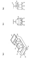
- Fig. 2 shows such a measuring point 8. This measuring point lies within a pipe segment.
- the pipes are in Fig. 2 denoted by 10 and 11 and are made of concrete. Between the two pipe ends 11a and 10a, a fitting ring and sealing ring 12 is provided.
- the ring has at the same time the task of uniformly transferring the pressing pressure to the tubes lying in front of it in the printing direction.
- This function is created by a certain flexibility of the ring.
- the compliance is achieved by using soft wood for the ring.
- a clamping ring 13 made of steel.
- the clamping ring 13 is the inner diameter of the tube eleventh customized. In other embodiments, the clamping ring is divided more.
- the clamping ring 13 is slotted in the direction of the central axis.
- the bracing device can act together on all parts of the rings. In other embodiments, a plurality of bracing devices are provided for multi-part rings.
- an adjustable bracket 14 Furthermore, the fixed parts of an adjustable bracket 14 are welded to the ring 13.
- the fixed parts include a support 16 and U-profile 15. To the moving parts another U-profile, which is provided with a not shown longitudinal slot and with longitudinal slots 19 and 21.
- the movable U-profile is clamped in any desired position by means of clamping screws with the fixed U-profile. The screws are provided at the ends with levers and engage through the slots 19 and 21 in threaded holes of the fixed U-profile. From the screws and levers is in Fig. 2 the lever 20 is shown.
- Fig. 3 also shows the levers 25 and 26.
- the lever 26 is located on the console side, which is the console side with the lever 25 and the slot 21 opposite. To the lever 26 includes the aforementioned slot, not shown.
- the movable U-profile has a measuring device connection 18 for receiving a tribrach as a holder for the measuring instruments and / or the measuring prisms.
- Fig. 4 shows the inventive console in measurement function with a standard tachymeter as a measuring device.
- a standard tachymeter as a measuring device.
- Trimble the product name
- This design allows you to track passive targets with active target identification.
- the instrument captures and tracks numerous conventional prisms and targets even at great distances.
- the target identification ensures the targeting of the right target. Thereby It is also possible to use several prisms in the measuring area.
- the device has servo motors and angle sensors, as well as an error compensation.
- the device has an internal computer for the tasks described above, as well as its own power supply and a wireless remote transmission of data. This can be used to follow work on a computer outside the channel and to influence it with planning information.
- the remote transmission implies that at increasing distances in the channel amplifiers for the radio signals are mounted in the building.
- the amplifiers pick up incoming weak signals and send amplified signals on.
- the Fig. 3 shows the console 14 in the collapsed state.
- the console 14 is pushed together after completion of the measurement process to release the interior of the channel.
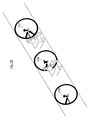
- Fig. 8 shows an annular channel with various fittings 50.
- a console 52 is provided with a double-armed, swing-out lever 53, which carries a total station 51 in the pivoted position.
- the lever is laterally swung in and out in other embodiments
- the Fig. 5 to 7 show a vehicle according to the invention.
- the vehicle facilitates the measurement, especially in smaller pipe cross-sections. There, the gauges no longer need to be carried in a stooping posture by the survey personnel through the pipes.
- the measuring devices can be easily transported by vehicle.
- the vehicle is three-wheeled, with two rear wheels 37,38 and one
- Front wheel 36 The rear wheels 37,38 are provided with an electric drive.
- the drive movement can be regulated electrically, in the
- the drive is powered by a battery which is arranged in a battery box 39.
- the battery box 39 is connected to the vehicle frame 35. From is located on the vehicle frame 35, a support surface 42 for transporting the measuring devices.
- the vehicle includes a handlebar 41 as a steering.
- the handlebar 41 is rotatably held in the vehicle frame 35 and opens into a fork in which the wheel 36 is held.
- a bucket seat is provided for the driver in the vehicle frame.
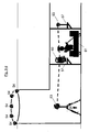
- Fig. 9 shows a schematic view of the beginning of a pipe jacking.
- a shaft 50 has been run off.
- the shaft is measured including the shaft bottom by means of a tachymeter 60.
- the total station 60 at the same time has an automatic adjustment to the horizontal.
- the tachymeter does not have the function and a separate device with this function is provided below the tachymeter.
- Such separate devices are commercially available under the designation automatic tripod AD-12.
- measuring points 54 at the earth's surface 53 are used at the same time.
- the measuring points are formed by prisms, which are targeted by the tachymeter.
- the measuring beams of the tachymeter are shown in dashed lines and designated 55.
- a pipe press is used during pipe jacking, with which a number of pipes - in the exemplary embodiment for a channel section 51 - are pressed into the ground.
- the tubes for the channel section 51 are each provided with a releasable clamping ring 56 in the embodiment.
- Each clamping ring carries in the embodiment of an extendable console 57 with four measuring positions. The measuring positions are in the embodiment in the middle of the channel, where they are easily accessible.
- Each console is positioned in the desired measuring position by a catch and secured by a clamping of the moving parts, so that even when the measurement is repeated a defined measuring position is given. Brackets without detents are preferably used when no return to the exact same measuring position is required after leaving the measuring position.
- Each console has in the embodiment a quick release for mounting different devices.
- the devices include tachymeters, prisms.
- the quick release allows a quick change as needed.
- the consoles are occupied in the embodiment in alternation with prisms and tachymeters. Through each tube, which further advances the already advanced in the ground pipes in the press drive and which is provided with a clamping ring and a console, a new situation arises.
- the measurement is passed from the manhole to the foremost pipe and, as needed, to the excavator in front of the foremost pipe.
- a tachymeter and two prisms are used.
- All measuring devices are moved in the exemplary embodiment with a vehicle 61.
- each new measurement / survey step starts from a saved / measured measurement point.
- the first survey step starts from a saved / measured tachymeter position in the manhole. This position has been derived from the measuring point 54 at the beginning of the manhole.
- a vehicle 61 has been lowered in the shaft and the prism 63 has been transported by the vehicle 61 to the next console 57.
- the tachymeter 60 is removed from the hitherto used tripod and moved with the vehicle 61 in the channel after the survey to put it on the first console 57.
- the prism 63 is placed on the tripod on the shaft bottom.
- Another prism 63 is moved to the second console and put on. This is in Fig. 9c shown.
- the prism 63 located on the stand is aimed at the tachymeter as well as the prism 63 on the second console. Is in Fig. 9d shown. Thereafter, the prism 63 can be disassembled from the tripod and re-mounted on the first console 57.
- the vehicle 61 brings the total station 60 from the first to the second console 57 and the prism previously placed on the second console is placed on the third console. This process is in Fig. 9e shown.
- the tachymeter measures the two prisms, FIG. 9f , The tachymeter misses every prism. This is called a sentence. If the tachymeter measures the prisms several times, one can speak of several sentences
- Each surveying step overlaps in the exemplary embodiment with the adjacent surveying steps.
- the total station is located between the two prisms. All measuring devices (tachymeter and prisms) leave the previous installation site on the consoles 57 in order to be placed on a different console in the same sequence of prism / tachymeter / prism. Nevertheless, the further survey results with the previous surveying results form a coherent chain of measurement results, because the consoles form a same, defined basis for all measuring instruments.
- more tachymeters and / or more prisms and more vehicles are used.
- a second vehicle 61 is in use.
- the vehicles have transport surfaces 62.
- the first vehicle (right vehicle in the picture) drives with a tachymeter 60 to the second console and occupies this with the Tachymeter 60.
- the second vehicle (left in the picture vehicle) drives to the first console and occupies it with the prism 63, which of the shaft stand has been removed, Fig. 9d ).
- the first vehicle drives to a third console and also occupies it with a prism 63 Fig. 11 the measuring process is shown with the measuring lines (dashed line).
- a tachymeter can determine its position by sighting and measuring the posterior prism (in the channel longitudinal direction) and after rotating, sighting and measuring the other, front prism.
- the next surveying step provides that the tachymeter and the rear prism are dismantled, then transported with the vehicle in surveying direction to not yet measured survey points and mounted there on the associated consoles.
- two vehicles 61 are provided.
- Surveying step shown is - after the first measuring point on the first console occupied by a prism 63, the second console is provided with a total station 60 and the third console is provided with a prism - calibrated.
- the tachymeter measures as in the previous embodiment in several sentences.
- the measuring devices are moved with the vehicles 61 for a further surveying step.
- a prism is provided in front of and behind the tachymeter, so that the measurement as in Fig. 11 can be done.
- the tachymeter and the prisms are transported with the carriage 61 through the tubes.
- the tachymeter and prisms are supported by the survey personnel.
- the carriages 61 are in the embodiment three-wheeled, with two rear wheels and a front wheel.
- the rear wheels are provided with an electric drive.
- the drive movement can be controlled electrically, in the embodiment of 0 to 10km per hour.
- the drive is powered by a battery, which is arranged in a battery box.
- the battery box is connected to the vehicle frame.
- the vehicle includes a handlebar steering.
- the handlebar is rotatably held in the vehicle frame and opens into a fork in which the front wheel is held.
- a bucket seat is provided for the driver in the vehicle frame.
- the first calibration of the tubes can only work with the tachymeter 60 in the shaft and a prism 63.
- the prism is driven by the carriage 61 to the first console 57 and placed there on the console.
- the transport of the measuring devices in the pipes is in Fig. 10 shown.
- the prism 63 on the first console can then be calibrated.
- consoles offer a total of four pull-out positions in the exemplary embodiment, it is possible to measure at up to four positions on the consolle. As far as a variety of measuring positions is also possible on the neighboring consoles, the number of possible measuring positions multiplies in the combination of these consoles.
- Fig. 15 The possibilities for varying the instrumentation setup with inventive consoles is in Fig. 15 shown.
- three consecutively arranged in a pipe jacking 75 consoles with 76, 81, 82 are designated.
- Each of the consoles has in the exemplary embodiment four horizontal juxtaposition options 77,78, 79, 80.
- the console 81 is intended for the installation of a tachymeter.
- the tachymeter can take each of the positions 77, 78,79, 80.
- the prisms can occupy each of the positions 77, 78, 79, 80. This allows various measuring paths that run parallel or intersecting and whose results can be compared with each other to control the measurement accuracy.
- prisms and tachymeters are provided side by side on individual consoles or on all consoles 76, 81, 82. This allows the simultaneous production of parallel, including intersecting measuring sections.
- combined tachymeters / prisms are also placed on consoles in the manner described in US Pat Fig. 16 is shown.
- Fig. 16 shows an embodiment in which find tachymeter 90 application, which are combined with two vertically above prisms 91 and 92. With the tachymeter 90 different prisms 91 and 92 are targeted. This results in measuring beams 93,94,95,96, which intersect.
- the first carriage 61 in the measuring direction always remains between the first prism in the measuring direction and the total station.
- the first prism and the tachymeter in the measuring direction are again loaded onto the first carriage in the measuring direction, before this carriage is moved forward in the measuring direction to the next console and the measuring tools are rebuilt on the console.
- the second carriage 61 may follow the first carriage 61 with the prism 64 when the first carriage 61 has cleared the way to the next console.
- Each step creates a single measuring section.
- the individual measuring sections together form the entire measuring section. In the case of several parallel individual measuring sections, these together form parallel total measuring sections.
- the individual measuring sections overlap.
- the survey is also used in the embodiment beyond to control at the end of the pipe a knife shield as a propulsion device.
- the first carriage in the measuring direction is limited to the transport of the first measuring tool in the measuring direction, while the second carriage 61 moves the total station and the last prism in the measuring direction.
- an additional carriage 61 is used, so that with three measuring tools each measuring tool can be assigned a separate car and the measuring process can be accelerated.
- the carriage is thereby moved under the consoles or driven past the consoles in order to collect the measuring tools after a measuring step and to redistribute them for the next measuring step.
- brackets can be pushed in to move the cart past.
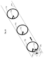
- FIG. 17 show a further embodiment with only two vehicles 174 and 175.
- Fig. 17 are provided in each pipe section of a channel 171 clamping rings designated 172.
- the clamping rings 172 have inventive, extendable brackets 173 for the installation of measuring instruments.
- a vehicle moves in the direction indicated by arrow in the channel 171.
- the vehicle 174 carries two gauges, namely a total station 178 and a prism 177. While the tachymeter 178 is worn in the rear direction, the prism 177 is carried on the vehicle in front.
- the vehicle 174 follows at a distance as shown in FIG Fig. 19 another carriage 175 is shown.
- the further carriage 175 carries a prism 179 at the front.
- the two cars 174 and 175 stop in the channel 171 when the drivers have come within reach of the consoles 173.
- Fig. 20 shows how the consoles are pulled out after stopping the vehicles.
- the pull-out direction is marked with an arrow.
- the extension of the consoles resulting from extension is shown schematically.
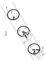
- Fig. 21 shows how after pulling out the consoles of the tachymeter 178 on a console 173 of a view in the middle clamping ring 172 and a prism 179 on a bracket 173 of a lying in the view left clamping ring 172 are placed.
- the vehicles 174 and 175 then proceed in the direction of the arrow.
- the vehicles 174 and 175 drive in the embodiment under the consoles 173.
- the driver can also fold down the back of her seat.
- the measuring devices can be located on the surfaces provided for this purpose.
- the vehicle 174 is moved past the console before the tachymeter is placed on the console. Then omitted for this vehicle passing by an extended console.
- Fig. 23 shows the arrival of the vehicle 174 on the adjacent, in the view right clamping ring with the console 173. At the same time the arrival of the vehicle 175 is shown in the view in the middle console 173 mounted thereon tachymeter 178.
- the total station 178 sends measuring beams 261 to the prism 179, with which an accurate position and height measurement of the prism 179 is carried out. Likewise, the exact location and height of the prism 177 is determined with the total station 178 by means of measuring beams 262.
- the prism 177 is dismantled again and mounted on the vehicle 174. Then, the vehicle 174 drives to the total station 178 so that the total station can also be dismantled and mounted on the vehicle 174. Also, the vehicle 175 travels back to disassemble the prism 179 and mount on the vehicle 175. The associated console is inserted.
- the tachymeter 178 with the vehicle 174 and then the prism 177 is degraded.
- the tachymeter 178 with the vehicle 175 and then the prism 179 are dismantled. Or, it is only the prism 179 degraded with the vehicle 175 and then the tachymeter 178th
- a further surveying step is started after the described surveying step after charging the measuring devices to the vehicles.
- the further measuring step comprises of the clamping rings of the first surveying step, which in the view of FIGS. 19 to 26 middle clamping ring 172 and the in the view FIGS. 19 to 26 right clamping ring and a in Fig. 27 and 28 dashed shown further clamping ring. All clamping rings of the further surveying step bear the designation 172 '.
- the vehicles 174 and 175 are already on the first two clamping rings 172; so that there can be started with the placement of the tachymeter 178 and the prism 179, as in Fig. 21 shown. Subsequently, the preparations for the further yermassing step continue, as in FIGS. 22 to 28 described.
- two measured and thus secured measuring points from the previously described surveying step are used in order to measure from there a further measuring point (prism on console of the clamping ring shown in dashed lines in the channel).
Landscapes
- Engineering & Computer Science (AREA)
- Mining & Mineral Resources (AREA)
- Physics & Mathematics (AREA)
- General Physics & Mathematics (AREA)
- General Life Sciences & Earth Sciences (AREA)
- Geochemistry & Mineralogy (AREA)
- Geology (AREA)
- Multimedia (AREA)
- Environmental & Geological Engineering (AREA)
- Life Sciences & Earth Sciences (AREA)
- Radar, Positioning & Navigation (AREA)
- Remote Sensing (AREA)
- Excavating Of Shafts Or Tunnels (AREA)
- Length Measuring Devices With Unspecified Measuring Means (AREA)
- Length Measuring Devices By Optical Means (AREA)
- Lining And Supports For Tunnels (AREA)
- Geophysics And Detection Of Objects (AREA)
Applications Claiming Priority (3)
| Application Number | Priority Date | Filing Date | Title |
|---|---|---|---|
| DE102009022750 | 2009-05-26 | ||
| DE102010004264 | 2010-01-10 | ||
| DE102010004231 | 2010-01-10 |
Publications (3)
| Publication Number | Publication Date |
|---|---|
| EP2256457A2 true EP2256457A2 (fr) | 2010-12-01 |
| EP2256457A3 EP2256457A3 (fr) | 2012-05-23 |
| EP2256457B1 EP2256457B1 (fr) | 2017-05-17 |
Family
ID=42664614
Family Applications (3)
| Application Number | Title | Priority Date | Filing Date |
|---|---|---|---|
| EP10005169.7A Not-in-force EP2256457B1 (fr) | 2009-05-26 | 2010-05-18 | Mesure de constructions souterraines, notamment lors de l'avancée souterraine, à l'aide de consoles |
| EP10005172.1A Not-in-force EP2325601B1 (fr) | 2009-05-26 | 2010-05-18 | Mesurage de constructions souterraines, notamment lors de l'avancement souterrain, à l'aide d'embases crapaud |
| EP10005157.2A Not-in-force EP2256456B1 (fr) | 2009-05-26 | 2010-05-18 | Mesure de constructions souterraines, notamment lors de l'avancée souterraine |
Family Applications After (2)
| Application Number | Title | Priority Date | Filing Date |
|---|---|---|---|
| EP10005172.1A Not-in-force EP2325601B1 (fr) | 2009-05-26 | 2010-05-18 | Mesurage de constructions souterraines, notamment lors de l'avancement souterrain, à l'aide d'embases crapaud |
| EP10005157.2A Not-in-force EP2256456B1 (fr) | 2009-05-26 | 2010-05-18 | Mesure de constructions souterraines, notamment lors de l'avancée souterraine |
Country Status (2)
| Country | Link |
|---|---|
| EP (3) | EP2256457B1 (fr) |
| DE (3) | DE102010020821A1 (fr) |
Cited By (5)
| Publication number | Priority date | Publication date | Assignee | Title |
|---|---|---|---|---|
| CN102735223A (zh) * | 2011-07-20 | 2012-10-17 | 中铁四局集团第一工程有限公司 | 试车场路面圆形凸台定位方法 |
| CN108507549A (zh) * | 2018-05-28 | 2018-09-07 | 中国核工业二三建设有限公司 | 高温气冷堆堆内石墨砖和碳砖的安装测量方法 |
| CN113588914A (zh) * | 2021-06-22 | 2021-11-02 | 清华大学 | 一种隧道硐壁岩体检测装置及岩体扰动状态测试方法 |
| CN115573774A (zh) * | 2022-09-13 | 2023-01-06 | 温州信达交通工程试验检测有限公司 | 一种基于机器视觉自适应隧道变形的检测装置 |
| WO2023056983A1 (fr) * | 2022-06-12 | 2023-04-13 | China Construction Seventh Engineering Division Corp., Ltd. | Dispositif et système de surveillance visuelle basés sur un robot de mesure |
Families Citing this family (4)
| Publication number | Priority date | Publication date | Assignee | Title |
|---|---|---|---|---|
| DE102012219100A1 (de) | 2012-10-19 | 2014-04-24 | Oliver Gebauer | Messsystem und Verfahren zur Vermessung von Räumen |
| DE202016101759U1 (de) | 2016-04-04 | 2016-04-25 | VMT GmbH Gesellschaft für Vermessungstechnik | Vorrichtung zum Halten eines Vermessungsinstruments |
| DE102023102055A1 (de) | 2023-01-27 | 2024-08-01 | VMT GmbH Gesellschaft für Vermessungstechnik | Vorrichtung zum Bestimmen der Position einer Tunnelbohrmaschine |
| DE202023100379U1 (de) | 2023-01-27 | 2023-02-14 | VMT GmbH Gesellschaft für Vermessungstechnik | Vorrichtung zum Bestimmen der Position einer Tunnelbohrmaschine |
Citations (10)
| Publication number | Priority date | Publication date | Assignee | Title |
|---|---|---|---|---|
| DE2607280A1 (de) | 1976-02-23 | 1977-09-01 | Laser Light Gmbh | Vorrichtung zum ausrichten eines laser-leitstrahlgeraetes zu einem an anderem ort aufgestellten richtgeraet, z.b. einem richtfernrohr |
| DE3120010A1 (de) | 1981-05-20 | 1982-12-09 | Ed. Züblin AG, 7000 Stuttgart | Verfahren zur positionsbestimmung eines vorgepressten hohlprofilstrangs und vorrichtung zur durchfuehrung des verfahrens |
| DE3733553A1 (de) | 1987-10-03 | 1989-04-13 | Marx Hans Juergen | Vorrichtung zum steuern einer schildvortriebsmaschine |
| DE4017833C1 (fr) | 1990-06-02 | 1992-02-06 | Dyckerhoff & Widmann Ag, 8000 Muenchen, De | |
| DE69103610T2 (de) | 1990-11-16 | 1994-12-22 | Mac Co | Geodätisches Lasersystem mit Referenzpunktmarkierfunktion. |
| EP1408344A1 (fr) | 2002-10-07 | 2004-04-14 | Geodata Ziviltechnikergesellschaft m.b.h. | Dispositif et méthode géodésique utilisant un laser à balayage |
| DE102004010114A1 (de) | 2004-02-27 | 2005-09-22 | Schlepütz, Roland | Positionsbestimmung von Erdbau-, Tunnelbau- und Rohrvortriebsmaschinen |
| DE69734622T2 (de) | 1996-03-18 | 2006-07-20 | Kabushiki Kaisha Topcon | Leitstrahlrichtungseinstellvorrichtung |
| DE102005012107A1 (de) | 2005-03-09 | 2006-09-21 | Angermeier Ingenieure Gmbh | Meßsystem und Verfahren zur geodätischen Vermessung von Objekten |
| DE102007014727A1 (de) | 2007-03-26 | 2008-11-20 | Keiper Gmbh & Co.Kg | Fahrzeugsitz, insbesondere Kraftfahrzeugsitz |
Family Cites Families (9)
| Publication number | Priority date | Publication date | Assignee | Title |
|---|---|---|---|---|
| DE6910361U (de) | 1969-03-13 | 1969-07-10 | Heinz Josef Dipl Ing Knapp | Deckenverkleidungsplatte fuer innenraeume |
| DE3306470A1 (de) * | 1982-08-17 | 1984-02-23 | Peter G. Tiedemann GmbH Ingenieur- u. Vermessungsbüro, 2000 Hamburg | Verfahren und vorrichtung zum vermessen unterirdischer vortriebe |
| DE3404495A1 (de) * | 1984-02-09 | 1985-08-14 | Gewerkschaft Eisenhütte Westfalia, 4670 Lünen | Polygonzug-vermessungsverfahren und vermessungseinrichtung |
| JP2509491B2 (ja) * | 1991-10-04 | 1996-06-19 | 鹿島建設株式会社 | トンネルの内空変位計測方法 |
| JP2711328B2 (ja) * | 1993-05-24 | 1998-02-10 | 西松建設株式会社 | トンネルの測量方法 |
| JP2687102B2 (ja) * | 1995-02-24 | 1997-12-08 | 株式会社関電工 | 測定台車による管路等の自動位置測定法 |
| DE19507346C2 (de) * | 1995-03-02 | 2002-06-13 | Dyckerhoff & Widmann Ag | Verfahren zum Steuern einer Vortriebsmaschine bei der Herstellung eines unterirdischen Hohlraumprofils sowie Einrichtung zur Durchführung des Verfahrens |
| JP4841080B2 (ja) * | 2001-09-04 | 2011-12-21 | 西松建設株式会社 | トンネル坑内の形状測定システムおよび形状測定方法 |
| DE102007014527A1 (de) * | 2007-03-27 | 2008-10-02 | Wilhelm, Jürgen | Klemmstativ für Vermessungszwecke in Tunneln |
-
2010
- 2010-05-18 EP EP10005169.7A patent/EP2256457B1/fr not_active Not-in-force
- 2010-05-18 DE DE102010020821A patent/DE102010020821A1/de not_active Withdrawn
- 2010-05-18 EP EP10005172.1A patent/EP2325601B1/fr not_active Not-in-force
- 2010-05-18 DE DE102010020822A patent/DE102010020822A1/de not_active Withdrawn
- 2010-05-18 EP EP10005157.2A patent/EP2256456B1/fr not_active Not-in-force
- 2010-05-19 DE DE102010021818A patent/DE102010021818A1/de not_active Withdrawn
Patent Citations (10)
| Publication number | Priority date | Publication date | Assignee | Title |
|---|---|---|---|---|
| DE2607280A1 (de) | 1976-02-23 | 1977-09-01 | Laser Light Gmbh | Vorrichtung zum ausrichten eines laser-leitstrahlgeraetes zu einem an anderem ort aufgestellten richtgeraet, z.b. einem richtfernrohr |
| DE3120010A1 (de) | 1981-05-20 | 1982-12-09 | Ed. Züblin AG, 7000 Stuttgart | Verfahren zur positionsbestimmung eines vorgepressten hohlprofilstrangs und vorrichtung zur durchfuehrung des verfahrens |
| DE3733553A1 (de) | 1987-10-03 | 1989-04-13 | Marx Hans Juergen | Vorrichtung zum steuern einer schildvortriebsmaschine |
| DE4017833C1 (fr) | 1990-06-02 | 1992-02-06 | Dyckerhoff & Widmann Ag, 8000 Muenchen, De | |
| DE69103610T2 (de) | 1990-11-16 | 1994-12-22 | Mac Co | Geodätisches Lasersystem mit Referenzpunktmarkierfunktion. |
| DE69734622T2 (de) | 1996-03-18 | 2006-07-20 | Kabushiki Kaisha Topcon | Leitstrahlrichtungseinstellvorrichtung |
| EP1408344A1 (fr) | 2002-10-07 | 2004-04-14 | Geodata Ziviltechnikergesellschaft m.b.h. | Dispositif et méthode géodésique utilisant un laser à balayage |
| DE102004010114A1 (de) | 2004-02-27 | 2005-09-22 | Schlepütz, Roland | Positionsbestimmung von Erdbau-, Tunnelbau- und Rohrvortriebsmaschinen |
| DE102005012107A1 (de) | 2005-03-09 | 2006-09-21 | Angermeier Ingenieure Gmbh | Meßsystem und Verfahren zur geodätischen Vermessung von Objekten |
| DE102007014727A1 (de) | 2007-03-26 | 2008-11-20 | Keiper Gmbh & Co.Kg | Fahrzeugsitz, insbesondere Kraftfahrzeugsitz |
Cited By (6)
| Publication number | Priority date | Publication date | Assignee | Title |
|---|---|---|---|---|
| CN102735223A (zh) * | 2011-07-20 | 2012-10-17 | 中铁四局集团第一工程有限公司 | 试车场路面圆形凸台定位方法 |
| CN102735223B (zh) * | 2011-07-20 | 2014-03-26 | 中铁四局集团第一工程有限公司 | 试车场路面圆形凸台定位方法 |
| CN108507549A (zh) * | 2018-05-28 | 2018-09-07 | 中国核工业二三建设有限公司 | 高温气冷堆堆内石墨砖和碳砖的安装测量方法 |
| CN113588914A (zh) * | 2021-06-22 | 2021-11-02 | 清华大学 | 一种隧道硐壁岩体检测装置及岩体扰动状态测试方法 |
| WO2023056983A1 (fr) * | 2022-06-12 | 2023-04-13 | China Construction Seventh Engineering Division Corp., Ltd. | Dispositif et système de surveillance visuelle basés sur un robot de mesure |
| CN115573774A (zh) * | 2022-09-13 | 2023-01-06 | 温州信达交通工程试验检测有限公司 | 一种基于机器视觉自适应隧道变形的检测装置 |
Also Published As
| Publication number | Publication date |
|---|---|
| DE102010020821A1 (de) | 2010-12-23 |
| DE102010021818A1 (de) | 2011-12-15 |
| EP2325601A3 (fr) | 2012-05-30 |
| EP2256456A3 (fr) | 2012-05-23 |
| EP2256457B1 (fr) | 2017-05-17 |
| EP2325601A2 (fr) | 2011-05-25 |
| EP2325601B1 (fr) | 2015-09-30 |
| EP2256457A3 (fr) | 2012-05-23 |
| EP2256456A2 (fr) | 2010-12-01 |
| EP2256456B1 (fr) | 2015-12-23 |
| DE102010020822A1 (de) | 2011-12-15 |
Similar Documents
| Publication | Publication Date | Title |
|---|---|---|
| EP2256457B1 (fr) | Mesure de constructions souterraines, notamment lors de l'avancée souterraine, à l'aide de consoles | |
| AT403066B (de) | Verfahren zum ermitteln der abweichungen der ist-lage eines gleisabschnittes | |
| EP0464363B1 (fr) | Procédé et dispositif pour la commande d'un bouclier | |
| EP2453205A1 (fr) | Dispositif de mesure et de construction pour mesurer et marquer des points spatiaux le long de courbes de niveau se déroulant horizontalement sur une surface | |
| CN107090861B (zh) | 用于在土地中产生沟槽的隔墙装置和方法 | |
| DE2701066C2 (de) | Verfahren und Vorrichtung zum Verlegen von Rohren | |
| DE4131673C2 (de) | Steuereinrichtung für eine Tunnelbohrmaschine | |
| EP2395150A2 (fr) | Dispositif et procédé destinés à la détermination de la position d'un appareil de travail | |
| DE102014005112A1 (de) | Messung unterirdischer Bauwerke, insbesonder beim unterirdischen Vortrieb, mit Prismen | |
| DE10052574C2 (de) | Lenkbare Erdrakete und ein Verfahren zum Lenken einer Erdrakete | |
| DE202010017291U1 (de) | Vorrichtung zur Messung unterirdischer Bauwerke, insbesondere beim unterirdischen Vortrieb, mit mindestens teilweiser mannloser Steuerung | |
| CN104632208A (zh) | 截割装置和工程机械 | |
| DE19507346C2 (de) | Verfahren zum Steuern einer Vortriebsmaschine bei der Herstellung eines unterirdischen Hohlraumprofils sowie Einrichtung zur Durchführung des Verfahrens | |
| WO2014166829A2 (fr) | Procédé permettant de déterminer l'orientation et la position de la machine de base portant le bouclier d'un tunnelier | |
| DE102021107197B4 (de) | Verfahren zur Positions- und Raumlagebestimmung eines Werkzeugs | |
| DE4439601A1 (de) | Verfahren zur Richtungssteuerung einer im Untertagebetrieb eingesetzten Maschine sowie zur Durchführung des Verfahrens geeigneten Maschine | |
| DE19918215C2 (de) | Verfahren zur Messung von radialen Verformungen eines Tunnelausbaus und Vorrichtung zur Durchführung des Verfahrens | |
| DE102018006464B4 (de) | Vorrichtung zum Positionieren einer elektronischen Einheit an einer Erdbohrvorrichtung | |
| WO1986000661A1 (fr) | Procede et installation de detection des parametres de commande pour la commande horizontale d'une machine de creusement | |
| EP3236203A1 (fr) | Procede et station totale destinés a commander un engin | |
| DE9106585U1 (de) | Vorrichtung zur unterirdischen Herstellung von Kanälen, Stollen o.dgl. | |
| DE2364508C3 (de) | Anordnung zum Verlegen eines Dränrohres in einem vorbestimmten Gefälle | |
| DE4420705A1 (de) | Verfahren und Vorrichtung zur kontinuierlichen automatischen Vermessung und Steuerung einer Vortriebsvorrichtung bei Tunnelbauten u. dgl. | |
| DE102014015442B4 (de) | Verfahren zum Setzen von Leitdrahtträgern und Setzvorrichtung | |
| US3442554A (en) | Machine for cutting a roadway in underground workings |
Legal Events
| Date | Code | Title | Description |
|---|---|---|---|
| PUAI | Public reference made under article 153(3) epc to a published international application that has entered the european phase |
Free format text: ORIGINAL CODE: 0009012 |
|
| AK | Designated contracting states |
Kind code of ref document: A2 Designated state(s): AL AT BE BG CH CY CZ DE DK EE ES FI FR GB GR HR HU IE IS IT LI LT LU LV MC MK MT NL NO PL PT RO SE SI SK SM TR |
|
| AX | Request for extension of the european patent |
Extension state: BA ME RS |
|
| PUAL | Search report despatched |
Free format text: ORIGINAL CODE: 0009013 |
|
| AK | Designated contracting states |
Kind code of ref document: A3 Designated state(s): AL AT BE BG CH CY CZ DE DK EE ES FI FR GB GR HR HU IE IS IT LI LT LU LV MC MK MT NL NO PL PT RO SE SI SK SM TR |
|
| AX | Request for extension of the european patent |
Extension state: BA ME RS |
|
| RIC1 | Information provided on ipc code assigned before grant |
Ipc: E21D 9/00 20060101ALI20120418BHEP Ipc: G01C 7/06 20060101AFI20120418BHEP |
|
| 17P | Request for examination filed |
Effective date: 20121123 |
|
| 17Q | First examination report despatched |
Effective date: 20140603 |
|
| GRAP | Despatch of communication of intention to grant a patent |
Free format text: ORIGINAL CODE: EPIDOSNIGR1 |
|
| INTG | Intention to grant announced |
Effective date: 20161206 |
|
| GRAS | Grant fee paid |
Free format text: ORIGINAL CODE: EPIDOSNIGR3 |
|
| GRAA | (expected) grant |
Free format text: ORIGINAL CODE: 0009210 |
|
| AK | Designated contracting states |
Kind code of ref document: B1 Designated state(s): AL AT BE BG CH CY CZ DE DK EE ES FI FR GB GR HR HU IE IS IT LI LT LU LV MC MK MT NL NO PL PT RO SE SI SK SM TR |
|
| REG | Reference to a national code |
Ref country code: GB Ref legal event code: FG4D Free format text: NOT ENGLISH |
|
| REG | Reference to a national code |
Ref country code: CH Ref legal event code: EP Ref country code: CH Ref legal event code: NV Representative=s name: ROTTMANN, ZIMMERMANN + PARTNER AG, CH Ref country code: FR Ref legal event code: PLFP Year of fee payment: 8 |
|
| REG | Reference to a national code |
Ref country code: IE Ref legal event code: FG4D Free format text: LANGUAGE OF EP DOCUMENT: GERMAN |
|
| REG | Reference to a national code |
Ref country code: AT Ref legal event code: REF Ref document number: 894866 Country of ref document: AT Kind code of ref document: T Effective date: 20170615 |
|
| REG | Reference to a national code |
Ref country code: DE Ref legal event code: R096 Ref document number: 502010013602 Country of ref document: DE |
|
| REG | Reference to a national code |
Ref country code: NL Ref legal event code: FP |
|
| REG | Reference to a national code |
Ref country code: LT Ref legal event code: MG4D |
|
| PG25 | Lapsed in a contracting state [announced via postgrant information from national office to epo] |
Ref country code: LT Free format text: LAPSE BECAUSE OF FAILURE TO SUBMIT A TRANSLATION OF THE DESCRIPTION OR TO PAY THE FEE WITHIN THE PRESCRIBED TIME-LIMIT Effective date: 20170517 Ref country code: GR Free format text: LAPSE BECAUSE OF FAILURE TO SUBMIT A TRANSLATION OF THE DESCRIPTION OR TO PAY THE FEE WITHIN THE PRESCRIBED TIME-LIMIT Effective date: 20170818 Ref country code: NO Free format text: LAPSE BECAUSE OF FAILURE TO SUBMIT A TRANSLATION OF THE DESCRIPTION OR TO PAY THE FEE WITHIN THE PRESCRIBED TIME-LIMIT Effective date: 20170817 Ref country code: ES Free format text: LAPSE BECAUSE OF FAILURE TO SUBMIT A TRANSLATION OF THE DESCRIPTION OR TO PAY THE FEE WITHIN THE PRESCRIBED TIME-LIMIT Effective date: 20170517 Ref country code: FI Free format text: LAPSE BECAUSE OF FAILURE TO SUBMIT A TRANSLATION OF THE DESCRIPTION OR TO PAY THE FEE WITHIN THE PRESCRIBED TIME-LIMIT Effective date: 20170517 Ref country code: HR Free format text: LAPSE BECAUSE OF FAILURE TO SUBMIT A TRANSLATION OF THE DESCRIPTION OR TO PAY THE FEE WITHIN THE PRESCRIBED TIME-LIMIT Effective date: 20170517 |
|
| PG25 | Lapsed in a contracting state [announced via postgrant information from national office to epo] |
Ref country code: PL Free format text: LAPSE BECAUSE OF FAILURE TO SUBMIT A TRANSLATION OF THE DESCRIPTION OR TO PAY THE FEE WITHIN THE PRESCRIBED TIME-LIMIT Effective date: 20170517 Ref country code: SE Free format text: LAPSE BECAUSE OF FAILURE TO SUBMIT A TRANSLATION OF THE DESCRIPTION OR TO PAY THE FEE WITHIN THE PRESCRIBED TIME-LIMIT Effective date: 20170517 Ref country code: LV Free format text: LAPSE BECAUSE OF FAILURE TO SUBMIT A TRANSLATION OF THE DESCRIPTION OR TO PAY THE FEE WITHIN THE PRESCRIBED TIME-LIMIT Effective date: 20170517 Ref country code: IS Free format text: LAPSE BECAUSE OF FAILURE TO SUBMIT A TRANSLATION OF THE DESCRIPTION OR TO PAY THE FEE WITHIN THE PRESCRIBED TIME-LIMIT Effective date: 20170917 Ref country code: BG Free format text: LAPSE BECAUSE OF FAILURE TO SUBMIT A TRANSLATION OF THE DESCRIPTION OR TO PAY THE FEE WITHIN THE PRESCRIBED TIME-LIMIT Effective date: 20170817 |
|
| PG25 | Lapsed in a contracting state [announced via postgrant information from national office to epo] |
Ref country code: EE Free format text: LAPSE BECAUSE OF FAILURE TO SUBMIT A TRANSLATION OF THE DESCRIPTION OR TO PAY THE FEE WITHIN THE PRESCRIBED TIME-LIMIT Effective date: 20170517 Ref country code: RO Free format text: LAPSE BECAUSE OF FAILURE TO SUBMIT A TRANSLATION OF THE DESCRIPTION OR TO PAY THE FEE WITHIN THE PRESCRIBED TIME-LIMIT Effective date: 20170517 Ref country code: DK Free format text: LAPSE BECAUSE OF FAILURE TO SUBMIT A TRANSLATION OF THE DESCRIPTION OR TO PAY THE FEE WITHIN THE PRESCRIBED TIME-LIMIT Effective date: 20170517 Ref country code: SK Free format text: LAPSE BECAUSE OF FAILURE TO SUBMIT A TRANSLATION OF THE DESCRIPTION OR TO PAY THE FEE WITHIN THE PRESCRIBED TIME-LIMIT Effective date: 20170517 Ref country code: CZ Free format text: LAPSE BECAUSE OF FAILURE TO SUBMIT A TRANSLATION OF THE DESCRIPTION OR TO PAY THE FEE WITHIN THE PRESCRIBED TIME-LIMIT Effective date: 20170517 |
|
| REG | Reference to a national code |
Ref country code: DE Ref legal event code: R097 Ref document number: 502010013602 Country of ref document: DE |
|
| REG | Reference to a national code |
Ref country code: IE Ref legal event code: MM4A |
|
| PG25 | Lapsed in a contracting state [announced via postgrant information from national office to epo] |
Ref country code: SM Free format text: LAPSE BECAUSE OF FAILURE TO SUBMIT A TRANSLATION OF THE DESCRIPTION OR TO PAY THE FEE WITHIN THE PRESCRIBED TIME-LIMIT Effective date: 20170517 |
|
| PLBE | No opposition filed within time limit |
Free format text: ORIGINAL CODE: 0009261 |
|
| STAA | Information on the status of an ep patent application or granted ep patent |
Free format text: STATUS: NO OPPOSITION FILED WITHIN TIME LIMIT |
|
| PG25 | Lapsed in a contracting state [announced via postgrant information from national office to epo] |
Ref country code: LU Free format text: LAPSE BECAUSE OF NON-PAYMENT OF DUE FEES Effective date: 20170518 |
|
| 26N | No opposition filed |
Effective date: 20180220 |
|
| GBPC | Gb: european patent ceased through non-payment of renewal fee |
Effective date: 20170817 |
|
| PG25 | Lapsed in a contracting state [announced via postgrant information from national office to epo] |
Ref country code: IE Free format text: LAPSE BECAUSE OF NON-PAYMENT OF DUE FEES Effective date: 20170518 |
|
| REG | Reference to a national code |
Ref country code: FR Ref legal event code: PLFP Year of fee payment: 9 |
|
| PG25 | Lapsed in a contracting state [announced via postgrant information from national office to epo] |
Ref country code: SI Free format text: LAPSE BECAUSE OF FAILURE TO SUBMIT A TRANSLATION OF THE DESCRIPTION OR TO PAY THE FEE WITHIN THE PRESCRIBED TIME-LIMIT Effective date: 20170517 |
|
| PG25 | Lapsed in a contracting state [announced via postgrant information from national office to epo] |
Ref country code: GB Free format text: LAPSE BECAUSE OF NON-PAYMENT OF DUE FEES Effective date: 20170817 |
|
| PGFP | Annual fee paid to national office [announced via postgrant information from national office to epo] |
Ref country code: DE Payment date: 20180531 Year of fee payment: 9 Ref country code: CH Payment date: 20180405 Year of fee payment: 9 |
|
| PGFP | Annual fee paid to national office [announced via postgrant information from national office to epo] |
Ref country code: FR Payment date: 20180528 Year of fee payment: 9 Ref country code: NL Payment date: 20180518 Year of fee payment: 9 Ref country code: BE Payment date: 20180530 Year of fee payment: 9 Ref country code: IT Payment date: 20180509 Year of fee payment: 9 Ref country code: AT Payment date: 20180523 Year of fee payment: 9 |
|
| PG25 | Lapsed in a contracting state [announced via postgrant information from national office to epo] |
Ref country code: MT Free format text: LAPSE BECAUSE OF FAILURE TO SUBMIT A TRANSLATION OF THE DESCRIPTION OR TO PAY THE FEE WITHIN THE PRESCRIBED TIME-LIMIT Effective date: 20170517 |
|
| PG25 | Lapsed in a contracting state [announced via postgrant information from national office to epo] |
Ref country code: HU Free format text: LAPSE BECAUSE OF FAILURE TO SUBMIT A TRANSLATION OF THE DESCRIPTION OR TO PAY THE FEE WITHIN THE PRESCRIBED TIME-LIMIT; INVALID AB INITIO Effective date: 20100518 Ref country code: MC Free format text: LAPSE BECAUSE OF FAILURE TO SUBMIT A TRANSLATION OF THE DESCRIPTION OR TO PAY THE FEE WITHIN THE PRESCRIBED TIME-LIMIT Effective date: 20170517 |
|
| PG25 | Lapsed in a contracting state [announced via postgrant information from national office to epo] |
Ref country code: CY Free format text: LAPSE BECAUSE OF NON-PAYMENT OF DUE FEES Effective date: 20170517 |
|
| PG25 | Lapsed in a contracting state [announced via postgrant information from national office to epo] |
Ref country code: MK Free format text: LAPSE BECAUSE OF FAILURE TO SUBMIT A TRANSLATION OF THE DESCRIPTION OR TO PAY THE FEE WITHIN THE PRESCRIBED TIME-LIMIT Effective date: 20170517 |
|
| REG | Reference to a national code |
Ref country code: DE Ref legal event code: R119 Ref document number: 502010013602 Country of ref document: DE |
|
| REG | Reference to a national code |
Ref country code: CH Ref legal event code: PL |
|
| REG | Reference to a national code |
Ref country code: NL Ref legal event code: MM Effective date: 20190601 |
|
| REG | Reference to a national code |
Ref country code: AT Ref legal event code: MM01 Ref document number: 894866 Country of ref document: AT Kind code of ref document: T Effective date: 20190518 |
|
| PG25 | Lapsed in a contracting state [announced via postgrant information from national office to epo] |
Ref country code: LI Free format text: LAPSE BECAUSE OF NON-PAYMENT OF DUE FEES Effective date: 20190531 Ref country code: AT Free format text: LAPSE BECAUSE OF NON-PAYMENT OF DUE FEES Effective date: 20190518 Ref country code: CH Free format text: LAPSE BECAUSE OF NON-PAYMENT OF DUE FEES Effective date: 20190531 |
|
| REG | Reference to a national code |
Ref country code: BE Ref legal event code: MM Effective date: 20190531 |
|
| PG25 | Lapsed in a contracting state [announced via postgrant information from national office to epo] |
Ref country code: TR Free format text: LAPSE BECAUSE OF FAILURE TO SUBMIT A TRANSLATION OF THE DESCRIPTION OR TO PAY THE FEE WITHIN THE PRESCRIBED TIME-LIMIT Effective date: 20170517 |
|
| PG25 | Lapsed in a contracting state [announced via postgrant information from national office to epo] |
Ref country code: DE Free format text: LAPSE BECAUSE OF NON-PAYMENT OF DUE FEES Effective date: 20191203 Ref country code: NL Free format text: LAPSE BECAUSE OF NON-PAYMENT OF DUE FEES Effective date: 20190601 Ref country code: IT Free format text: LAPSE BECAUSE OF NON-PAYMENT OF DUE FEES Effective date: 20190518 |
|
| PG25 | Lapsed in a contracting state [announced via postgrant information from national office to epo] |
Ref country code: BE Free format text: LAPSE BECAUSE OF NON-PAYMENT OF DUE FEES Effective date: 20190531 Ref country code: PT Free format text: LAPSE BECAUSE OF FAILURE TO SUBMIT A TRANSLATION OF THE DESCRIPTION OR TO PAY THE FEE WITHIN THE PRESCRIBED TIME-LIMIT Effective date: 20170517 |
|
| PG25 | Lapsed in a contracting state [announced via postgrant information from national office to epo] |
Ref country code: FR Free format text: LAPSE BECAUSE OF NON-PAYMENT OF DUE FEES Effective date: 20190531 |
|
| PG25 | Lapsed in a contracting state [announced via postgrant information from national office to epo] |
Ref country code: AL Free format text: LAPSE BECAUSE OF FAILURE TO SUBMIT A TRANSLATION OF THE DESCRIPTION OR TO PAY THE FEE WITHIN THE PRESCRIBED TIME-LIMIT Effective date: 20170517 |