EP2257007A2 - Verfahren und Vorrichtung zur blockweisen Entscheidungs-Feedback-Entzerrung für drahtlose Kommunikation - Google Patents
Verfahren und Vorrichtung zur blockweisen Entscheidungs-Feedback-Entzerrung für drahtlose Kommunikation Download PDFInfo
- Publication number
- EP2257007A2 EP2257007A2 EP10175637A EP10175637A EP2257007A2 EP 2257007 A2 EP2257007 A2 EP 2257007A2 EP 10175637 A EP10175637 A EP 10175637A EP 10175637 A EP10175637 A EP 10175637A EP 2257007 A2 EP2257007 A2 EP 2257007A2
- Authority
- EP
- European Patent Office
- Prior art keywords
- feed
- feedback filter
- reliability parameter
- feedback
- equalization
- Prior art date
- Legal status (The legal status is an assumption and is not a legal conclusion. Google has not performed a legal analysis and makes no representation as to the accuracy of the status listed.)
- Granted
Links
Images


Classifications
-
- H—ELECTRICITY
- H04—ELECTRIC COMMUNICATION TECHNIQUE
- H04L—TRANSMISSION OF DIGITAL INFORMATION, e.g. TELEGRAPHIC COMMUNICATION
- H04L25/00—Baseband systems
- H04L25/02—Details ; arrangements for supplying electrical power along data transmission lines
- H04L25/03—Shaping networks in transmitter or receiver, e.g. adaptive shaping networks
- H04L25/03006—Arrangements for removing intersymbol interference
- H04L25/03012—Arrangements for removing intersymbol interference operating in the time domain
- H04L25/03019—Arrangements for removing intersymbol interference operating in the time domain adaptive, i.e. capable of adjustment during data reception
- H04L25/03057—Arrangements for removing intersymbol interference operating in the time domain adaptive, i.e. capable of adjustment during data reception with a recursive structure
- H04L25/03063—Arrangements for removing intersymbol interference operating in the time domain adaptive, i.e. capable of adjustment during data reception with a recursive structure using fractionally spaced delay lines or combinations of fractionally and integrally spaced taps
-
- H—ELECTRICITY
- H04—ELECTRIC COMMUNICATION TECHNIQUE
- H04L—TRANSMISSION OF DIGITAL INFORMATION, e.g. TELEGRAPHIC COMMUNICATION
- H04L25/00—Baseband systems
- H04L25/02—Details ; arrangements for supplying electrical power along data transmission lines
- H04L25/03—Shaping networks in transmitter or receiver, e.g. adaptive shaping networks
- H04L25/03006—Arrangements for removing intersymbol interference
- H04L25/03012—Arrangements for removing intersymbol interference operating in the time domain
- H04L25/03019—Arrangements for removing intersymbol interference operating in the time domain adaptive, i.e. capable of adjustment during data reception
- H04L25/03057—Arrangements for removing intersymbol interference operating in the time domain adaptive, i.e. capable of adjustment during data reception with a recursive structure
-
- H—ELECTRICITY
- H04—ELECTRIC COMMUNICATION TECHNIQUE
- H04L—TRANSMISSION OF DIGITAL INFORMATION, e.g. TELEGRAPHIC COMMUNICATION
- H04L25/00—Baseband systems
- H04L25/02—Details ; arrangements for supplying electrical power along data transmission lines
- H04L25/03—Shaping networks in transmitter or receiver, e.g. adaptive shaping networks
- H04L25/03006—Arrangements for removing intersymbol interference
- H04L25/03159—Arrangements for removing intersymbol interference operating in the frequency domain
Definitions
- Provisional Application Serial No. 60/666,334 entitled “METHOD AND APPARATUS FOR DECISION-FEEDBACK EQUALIZATION IN WIRELESS COMMUNICATIONS”
- Provisional Application Serial No. 60/666,416 entitled “METHOD AND APPARATUS FOR ADAPTIVE EQUALIZATION IN WIRELESS COMMUNICATIONS,” both filed March 29, 2005, assigned to the assignee hereof, and expressly incorporated herein by reference.
- the present disclosure relates generally to communication, and more specifically to techniques for performing equalization in a communication system.
- a transmitter In a communication system, a transmitter typically processes (e.g., encodes, interleaves, symbol maps, spreads, and scrambles) traffic data to generate a sequence of chips. The transmitter then processes the chip sequence to generate a radio frequency (RF) signal and transmits the RF signal via a communication channel.
- RF radio frequency
- the communication channel distorts the RF signal with a channel response and further degrades the RF signal with noise and interference from other transmitters.
- a receiver receives the transmitted RF signal and processes the received RF signal to obtain samples.
- the receiver may perform equalization on the samples to obtain estimates of the chips sent by the transmitter.
- the receiver then processes (e.g., descrambles, despreads, demodulates, deinterleaves, and decodes) the chip estimates to obtain decoded data.
- the equalization typically has a large impact on the quality of the chip estimates as well as the overall performance.
- an apparatus which includes at least one processor and a memory.
- the processor(s) derive a feed-forward filter response and a feedback filter response based on a channel estimate and a reliability parameter and further without constraint on the feedback filter response or with a constraint of no feedback for an on-time sample.
- the reliability parameter is indicative of the reliability of the feedback used for equalization and may be frequency dependent or frequency invariant.
- the processor(s) perform equalization with the feed-forward and feedback filter responses.
- a method in which a feed-forward filter response and a feedback filter response are derived based on a channel estimate and a reliability parameter and further without constraint on the feedback filter response or with a constraint of no feedback for an on-time sample. Equalization is performed with the feed-forward and feedback filter responses.
- an apparatus which includes means for deriving a feed-forward filter response and a feedback filter response based on a channel estimate and a reliability parameter and further without constraint on the feedback filter response or with a constraint of no feedback for an on-time sample.
- the apparatus further includes means for performing equalization with the feed-forward and feedback filter responses.
- an apparatus which includes at least one processor and a memory.
- the processor(s) derive multiple feed-forward filter responses for multiple signal copies based on channel estimates for the multiple signal copies and a reliability parameter.
- the multiple signal copies may be obtained from over-sampling and/or multiple receive antennas.
- the processor(s) also derive a feedback filter response based on the channel estimates and the reliability parameter.
- the processor(s) perform equalization on input symbols for the multiple signal copies with the multiple feed-forward filter responses and the feedback filter response.
- a method in which multiple feed-forward filter responses for multiple signal copies are derived based on channel estimates for the multiple signal copies and a reliability parameter.
- a feedback filter response is derived based on the channel estimates and the reliability parameter.
- Equalization is performed on input symbols for the multiple signal copies with the multiple feed-forward filter responses and the feedback filter response.
- an apparatus which includes means for deriving multiple feed-forward filter responses for multiple signal copies based on channel estimates for the multiple signal copies and a reliability parameter, means for deriving a feedback filter response based on the channel estimates and the reliability parameter, and means for performing equalization on input symbols for the multiple signal copies with the multiple feed-forward filter responses and the feedback filter response.
- an apparatus which includes at least one processor and a memory.
- the processor(s) estimate a reliability parameter based on a first data block that is decoded correctly, derive a feed-forward filter response and a feedback filter response based on a channel estimate and the reliability parameter, and perform equalization for a second data block with the feed-forward and feedback filter responses.
- a method in which a reliability parameter is estimated based on a first data block that is decoded correctly.
- a feed-forward filter response and a feedback filter response are derived based on a channel estimate and the reliability parameter.
- Equalization is performed for a second data block with the feed-forward and feedback filter responses.
- an apparatus which includes means for estimating a reliability parameter based on a first data block that is decoded correctly, means for deriving a feed-forward filter response and a feedback filter response based on a channel estimate and the reliability parameter, and means for performing equalization for a second data block with the feed-forward and feedback filter responses.
- FIG. 1A shows a time-domain model of a communication channel.
- FIG. 1B shows a frequency-domain model of a communication channel.
- FIG. 2A shows a chip-spaced DFE with a time-domain feedback filter.
- FIG. 2B shows a chip-spaced DFE with a frequency-domain feedback filter.
- FIG. 3 shows a frequency-domain model for a chip-space DFE.
- FIG. 4 shows a process to derive feed-forward and feedback filter responses.
- FIG. 5 shows a process to perform decision feedback equalization.
- FIG. 6A shows a fractionally-spaced DFE with a time-domain feedback filter.
- FIG. 6B shows a fractionally-spaced DFE with a frequency-domain feedback filter.
- FIG. 7 shows a frequency-domain model for a fractionally-spaced DFE.
- FIG. 8 shows a process to derive feed-forward and feedback filter responses.
- FIG. 9 shows a process to perform equalization for multiple signal copies.
- FIG. 10 shows a process to perform decision feedback equalization based on a reliability parameter derived from correctly decoded data blocks.
- FIG. 11 shows a block diagram of a transmitter and a receiver.
- Time-domain scalars are denoted by lower case text with index n for sample period, e.g., h ( n ).
- Frequency-domain scalars are denoted by upper case text with index k for frequency bin, e.g., H ( k ).
- Time-domain vectors are denoted by bolded lower case cursive text, e.g., h .
- Time-domain matrices are denoted by bolded upper case cursive text, e.g., Frequency-domain vectors are denoted by bolded lower case regular text, e.g., h .
- Frequency-domain matrices are denoted by bolded upper case regular text, e.g., H .
- the terms “chips” and “samples” generally refer to time-domain quantities, and the term “symbols” generally refers to frequency-domain quantities.
- FIG. 1A shows a time-domain model 100 of a communication system with a transmitter 110 and a receiver 150.
- Model 100 assumes that the received signal is sampled at chip rate so that the sample rate is equal to the chip rate.
- Transmitter 110 processes traffic data and generates transmit chips s ( n ), which are sent via a communication channel 120.
- Channel 120 is modeled with a time-domain impulse response of h ( n ) in block 124 and additive noise of n ( n ) via a summer 126.
- the channel impulse response h ( n ) includes the effects of the pulse shaping filter at transmitter 110, the propagation channel, the front-end filter at receiver 150, and so on.
- Receiver 150 obtains input samples r ( n ) via channel 120 and performs equalization on the input samples to obtain chip estimates ⁇ ( n ), which are estimates of the transmit chips s ( n ).
- FIG. 1B shows a frequency-domain model 102 of the communication system in FIG. 1A .
- Frequency-domain model 102 is equivalent to time-domain model 100.
- the transmit chips s ( n ) from transmitter 110 are sent via a communication channel 130.
- the time-domain transmit chips s ( n ) are transformed to the frequency domain with a K-point fast Fourier transform (FFT) or a K-point discrete Fourier transform (DFT) by a unit 132 to obtain frequency-domain transmit symbols S ( k ).
- FFT fast Fourier transform
- DFT discrete Fourier transform
- Channel 130 is modeled with a channel frequency response of H ( k ) in block 134 and additive noise of N ( k ) via a summer 136.
- a unit 138 performs a K-point FFT/DFT on the time-domain noise n ( n ) and provides the frequency-domain noise N ( k ).
- a unit 140 performs a K-point inverse FFT (IFFT) or a K-point inverse DFT (IDFT) on the frequency-domain input symbols R ( k ) from summer 136 and provides the time-domain input samples r ( n ) to receiver 150.
- IFFT K-point inverse FFT
- IDFT K-point inverse DFT
- Receiver 150 may process the input samples on a block-by-block basis.
- a data block may also be called a packet, a frame, and so on.
- each data block contains K input samples.
- T is a K ⁇ 1 vector of transmit symbols
- H is a K ⁇ K channel response matrix containing channel gains H (1) through H (K) along the diagonal and zeros elsewhere
- W K is a K ⁇ K Fourier matrix
- W ⁇ K - 1 is a K ⁇ K inverse Fourier matrix
- T denotes a transpose.
- the noise may be assumed to be additive white Gaussian noise (AWGN) with zero mean and a covariance matrix of N t ⁇ I , where N t is the variance of the noise and I is the identity matrix.
- AWGN additive white Gaussian noise
- W k ⁇ n e - j ⁇ 2 ⁇ ⁇ ⁇ k - 1 ⁇ n - 1 / K .
- the "-1" is due to indices k and n starting with 1 instead of 0.
- Receiver 150 may perform decision feedback equalization on each block of input samples.
- a decision feedback equalizer typically includes a feed-forward filter and a feedback filter.
- the feed-forward filter is implemented in the frequency domain
- the feedback filter may be implemented in either the time domain or the frequency domain.
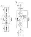
- FIG. 2A shows a block diagram of a model 200 with a DFE having a time-domain feedback filter.
- a transmitter 210 generates transmit chips s ( n ), which are sent via a communication channel 220.
- Channel 220 is modeled with a channel impulse response of h ( n )in block 224 and additive noise of n ( n ) via a summer 226.
- a receiver 250a obtains input samples r ( n ) via channel 220.
- an FFT/DFT unit 252 transforms the input samples to the frequency domain and provides input symbols R ( k ).
- a feed-forward filter 260 filters the input symbols and provides filtered symbols X ( k ).
- An IFFT/IDFT unit 264 transforms the filtered symbols to the time domain and provides filtered samples x ( n ).
- a summer 266 subtracts feedback samples y ( n ) from the filtered samples x ( n ) and provides equalized samples z ( n ).
- a slicer 270 slices or quantizes the equalized samples z ( n ) and provides chip estimates ⁇ ( n ).
- a feedback filter 272 filters the chip estimates and provides the feedback samples y ( n ).
- FIG. 2B shows a block diagram of a model 202 with a DFE having a frequency-domain feedback filter.
- Transmitter 210 and communication channel 220 are as described above for FIG. 2A .
- a receiver 250b obtains input samples r ( n ) via channel 220.
- FFT/DFT unit 252 and feed-forward filter 260 operate on the input samples as described above for FIG. 2A and provide filtered symbols X ( k ).
- Summer 266 subtracts feedback symbols Y ( k ) from the filtered symbols X ( k ) and provides equalized symbols Z ( k ).
- An IFFT/IDFT unit 268 transforms the equalized symbols to the time domain and provides equalized samples z ( n ).
- Slicer 270 slices the equalized samples z ( n ) and provides chip estimates ⁇ ( n ).
- An FFT/DFT unit 274 transforms the chip estimates ⁇ ( n ) to the frequency domain and provides symbol estimates ⁇ ( k ).
- a feedback filter 280 filters the symbol estimates and provides the feedback symbols Y ( k ).
- a linear convolution of the input samples and the impulse response of a time-domain feed-forward filter is equivalent to a cyclic convolution.
- the time-domain feed-forward filter may be represented in the frequency domain by a block-wise feed-forward filter having a frequency response denoted by a K ⁇ K diagonal matrix F .
- Matrix F contains K filter coefficients along the diagonal for the K frequency bins and zeros elsewhere.
- T is a K ⁇ 1 vector of feedback samples
- B ⁇ b 0 0 ⁇ 0 b L - 1 ⁇ b 2 b 1 b 1 b 0 ⁇ 0 0 b L - 1 ⁇ b 2 ⁇ ⁇ ⁇ ⁇ ⁇ ⁇ 0 ⁇ 0 b L - 1 ⁇ b 2 ⁇ ⁇ ⁇ ⁇ ⁇ ⁇ 0 ⁇ 0 b L - 1 ⁇ b 2 b 1 b 0 is a K ⁇ K circular matrix.
- the circular matrix contains elements of the impulse response vector b .
- the time-domain feedback filter may be represented in the frequency domain by a block-wise feedback filter having a frequency response denoted by a K ⁇ K diagonal matrix B .
- FIG. 3 shows a frequency-domain model 300 with a chip-space DFE.
- Model 300 is equivalent to model 200 in FIG. 2A and model 202 in FIG. 2B .
- a transmitter 310 generates time-domain transmit chips s ( n ), which are sent via a communication channel 330.
- Channel 330 is modeled with an FFT/DFT unit 332 that transforms the transmit chips to transmit symbols S ( k ), a block 334 for the channel frequency response H ( k ), an FFT/DFT unit 338 that transforms time-domain noise n ( n ) to frequency-domain noise N ( k ), and a summer 336 that sums the outputs of blocks 334 and 338 and provides input symbols R ( k ) to a receiver 350.
- a feed-forward filter 360 filters the input symbols R ( k ) and provides filtered symbols X ( k ).
- a summer 366 subtracts feedback symbols Y ( k ) from the filtered symbols X ( k ) and provides equalized symbols Z ( k ).
- An IFFT/IDFT unit 368 transforms the equalized symbols Z ( k ) to the time domain and provides equalized samples z ( n ).
- a slicer 370 slices the equalized samples z ( n ) and provides chip estimates ⁇ ( n ).
- An FFT/DFT unit 374 transforms the chip estimates to the frequency domain and provides symbol estimates ⁇ ( k ).
- a feedback filter 380 filters the symbol estimates and provides the feedback symbols Y ( k ).
- the feed-forward filter frequency response F and the feedback filter frequency response B may be derived in various manners.
- the filter responses F and B are derived based on a minimum mean square error (MMSE) criterion that minimizes the mean square error (MSE) between the transmit chips s and the equalized samples z .
- E s is the energy-per-chip for the transmit chips s ( n )
- E ⁇ ⁇ denotes an expectation operation
- ⁇ [ ⁇ (1) ⁇ (2) ... ⁇ (K)] T is a K ⁇ 1 vector of symbol estimates
- R is a K ⁇ K feedback correlation matrix
- H denotes a conjugate transpose.
- Equation (13) indicates that the transmit chips s as well as the chip estimates ⁇ are uncorrelated.
- Equation (14) describes the correlation between the transmit chips s and the chip estimates ⁇ . This correlation is related to the reliability of the decision feedback for the DFE.
- Equation (12) may be expanded and combined with equations (11), (13) and (14).
- 2 + N t ⁇ ⁇ k 1 K
- F ( k ) is the feed-forward filter
- the feed-forward and feedback filter responses are derived without any constraint on the feedback filter.
- Vector b contains L time-domain filter taps b 0 through b L-1 .
- 2 + N t , for k 1 , ... , K .
- 2 + N t , for k 1 , ... , K .
- R ( k , k ) is indicative of the reliability of the feedback from the slicer.
- the feedback filter is typically used to compensate only for intersymbol interference and hence there is no feedback related to the on-time sample.
- Coefficient b 0 determines the feedback for the on-time sample and may be set to zero.
- Q ( m , l ), for m , l 1, ..., (L-1), is the element in row m and column l of Q .
- 2 + N t ⁇ e j ⁇ 2 ⁇ ⁇ ⁇ k - 1 ⁇ m / K , where p ( m ), for m 1, ..., (L-1), is the m -th element of p .
- Vector b may be derived based on matrix Q and vector p , as shown in equation (18). Vector b may then be transformed with an FFT/DFT to obtain the feedback filter response B ( k ), as shown in equation (19). To reduce computation, L may be selected to be much less than K but large enough to cover significant ISI components.
- ⁇ is a reliability factor for the feedback and is not dependent on frequency.
- 2 + N t , for m 1 , ... , L - 1 .
- 2 + N t , for k 1 , ... , K .
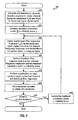
- FIG. 4 shows an embodiment of a process 400 for deriving the feed-forward and feedback filter responses and equalizing the input symbols.
- a channel impulse response h ( n ) is estimated and transformed with an FFT/DFT to obtain a channel frequency response H ( k ) (block 412).
- a feedback correlation matrix R or a reliability factor ⁇ is initialized, e.g., to zero for the first iteration (block 414).
- a feed-forward filter response F ( k ) is derived based on the channel frequency response H ( k ) and the feedback correlation R ( k,k ) or the reliability factor ⁇ (block 422).
- a feedback filter response B ( k ) is also derived based on the channel frequency response H ( k ) and the feedback correlation R ( k , k ) or the reliability factor ⁇ (block 424).
- the feed-forward and feedback filter responses may be derived without any constraint on the feedback filter, e.g., as shown in equations (16) and (17).
- the chip estimates are not available for the first iteration. Hence, the derivation of the feedback filter response may be omitted for the first iteration.
- matrix Q and vector p may be derived based on the channel frequency response H ( k ) and the feedback correlation R ( k,k ) or the reliability factor ⁇ , e.g., as shown in equations (20) and (21) or equations (25) and (26).
- the feedback filter response may then be derived based on matrix Q and vector p , e.g., as shown in equations (18) and (19).
- the feed-forward filter response and the feedback filter response may be derived independently of one another.
- the feed-forward filter response may be derived first, and the feedback filter response may be derived with the feed-forward filter response, e.g., as shown in equation (24).
- the feedback filter response may be derived first, and the feed-forward filter response may be derived with the feed-forward filter response e.g., as shown in equation (22) or (27).
- Equalization is performed on the input symbols R ( k ) based on the feed-forward and feedback filter responses, e.g., as shown in equations (9) through (11) (block 426).
- the equalized symbols are transformed and sliced to obtain chip estimates ⁇ ( n ) (block 428).
- Equalization may be performed for one or multiple iterations. Each iteration may also be called a stage, a round, and so on.
- a determination is made whether to perform another iteration (block 430). If the answer is 'Yes', then the feedback correlation matrix R or the reliability factor ⁇ is updated as described below (block 432). Matrix R or reliability factor ⁇ should become larger for each iteration. The process then returns to block 422 to update the feed-forward and feedback filter responses and to perform equalization with the updated filter responses. Otherwise, if all iterations are completed and the answer is 'No' for block 430, then the process terminates.
- FIG. 5 shows an embodiment of a process 500 for performing decision feedback equalization.
- a channel estimate is obtained for a communication channel (block 512).
- the channel estimate may be a channel impulse response estimate, a channel frequency response estimate, and so on.
- a reliability parameter indicative of the reliability of the feedback used for equalization is initialized (block 514).
- the reliability parameter may be a feedback correlation matrix R , a reliability factor ⁇ , and/or some other quantity.
- the reliability parameter may be a function of frequency or may be frequency invariant.
- a feed-forward filter response is derived based on the channel estimate and the reliability parameter (block 522).
- a feedback filter response is derived based on the channel estimate and the reliability parameter (block 524).
- the feed-forward and feedback filter responses may be derived (1) without any constraint on the feedback filter, (2) with a constraint of no feedback for an on-time sample, or (3) based on some other constraint or condition.
- the feed-forward and feedback filter responses may be derived based on MMSE or some other criterion.
- the feed-forward and feedback filter responses may be derived independently of one another, the feedback filter response may be derived based on the feed-forward filter response, or the feed-forward filter response may be derived based on the feedback filter response.
- the feed-forward filter response may be in the frequency domain and comprise frequency-domain coefficients.
- the feedback filter response may be in (1) the frequency domain and comprise frequency-domain coefficients or (2) the time domain and comprise time-domain taps.
- different feed-forward and feedback filter responses may be derived for different filter constraints, assumptions on feedback reliability, design criteria, and so on.
- Equalization is performed with the feed-forward and feedback filter responses (block 526).
- the equalization may be performed on a block-by-block basis for each received data block. Equalization may also be performed for multiple iterations. If another iteration is to be performed, as determined in block 530, then the reliability parameter may be updated, and the feed-forward and feedback filter responses for the next iteration may be derived based on the channel estimate and the updated reliability parameter.
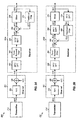
- FIG. 6A shows a time-domain model 600 for a communication system with two times (2 ⁇ ) over-sampling at a receiver 650a.
- a transmitter 610 processes traffic data and generates transmit chips s ( n' ) at the chip rate, where n' is an index for chip period.
- transmitter 610 sends the transmit chips via a communication channel 620 to receiver 650a.
- an upsampler 612 inserts a zero after each transmit chip and provides output samples s ( n ) at the sample rate.
- Channel 620 is modeled with a channel impulse response of h ( n ) in block 624 and additive noise of n ( n ) via a summer 626.
- FIG. 6A also shows a fractionally-spaced DFE with a time-domain feedback filter.
- the term "fractionally-spaced" refers to sampling at a higher rate than the chip rate, and it is usually higher than the rate required by Nyquist sampling theorem.
- Receiver 650a digitalizes the received signal at twice the chip rate and obtains input samples r ( n ) at a sample rate that is twice the chip rate.
- the two redundant signal copies are referred to as a lower copy (L) and an upper copy (U).
- Feed-forward filter 660a filters the input symbols R L ( k ) and provides filtered symbols X L ( k ) for the lower copy.
- Feed-forward filter 660b filters the input symbols R U ( k ) and provides filtered symbols X U ( k ) for the upper copy.
- a summer 662 sums the filtered symbols X L ( k ) and X U ( k ) on a bin-by-bin basis.
- a unit 664 performs a K-point IFFT/IDFT on the filtered symbols and provides filtered samples x ( n ) at the chip rate.
- the summing of X L ( k ) and X U ( k ) by summer 662, scaling by 1/2 with unit 663, and K-point IFFT/IDFT by unit 664 is equivalent to performing a 2K-point IFFT/IDFT on X L ( k ) and X U ( k ) followed by decimation by a factor of two to obtain the filtered samples x ( n ) at the chip rate.
- a summer 666 subtracts feedback samples y ( n ) from the filtered samples x ( n ) and provides equalized samples z ( n ).
- a slicer 670 slices the equalized samples z(n) and provides chip estimates ⁇ ( n ).
- a feedback filter 672 filters the chip estimates and provides the feedback samples y ( n ).
- FIG. 6B shows a block diagram of a model 602 with a fractionally-spaced DFE having a frequency-domain feedback filter.
- Transmitter 610 and channel 620 are as described above for FIG. 6A .
- a receiver 650b obtains input samples r ( n ) at the sample rate.
- FFT/DFT unit 652, feed-forward filters 660a and 660b, summer 662, and gain element 663 operate on the input samples as described above for FIG. 6A and provide filtered symbols X ( k ) .
- Summer 666 subtracts feedback symbols Y ( k ) from the filtered symbols X ( k ) and provides equalized symbols Z ( k ).
- An IFFT/IDFT unit 668 transforms the equalized symbols to the time domain and provides equalized samples z ( n ).
- Slicer 670 slices the equalized samples z ( n ) and provides chip estimates ⁇ ( n ).
- An FFT/DFT unit 674 transforms the chip estimates to the frequency domain and provides symbol estimates ⁇ ( k ).
- a feedback filter 680 filters the symbol estimates and provides the feedback symbols Y ( k ).
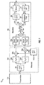
- FIG. 7 shows a frequency-domain model 700 with a fractionally-spaced DFE.
- Model 700 is equivalent to model 600 in FIG. 6A and model 602 in FIG. 6B .
- a transmitter 710 generates time-domain transmit chips s ( n' ) at the chip rate, which are sent via a communication channel 730.
- the channel for the lower signal copy is modeled by a frequency response of H L ( k ) in block 734a and additive noise of N L ( k ) via a summer 736a.
- the channel for the upper signal copy is modeled by a frequency response of H U ( k ) in block 734b and additive noise of N U ( k ) via a summer 736b.
- a unit 738 transforms the time-domain noise n ( n ) and provides the frequency-domain noise N L ( k ) and N U ( k ) for the lower and upper copies, respectively.
- a receiver 750 obtains input symbols R L ( k ) and R U ( k ) for the lower and upper copies, respectively.
- Feed-forward filters 760a and 760b filter the input symbols R L ( k ) and R U ( k ) and provide filtered symbols X L ( k ) and X U ( k ), respectively.
- the filtered symbols X L ( k ) and X U ( k ) are summed by a summer 762 and scaled with a gain of 1/2 by a gain element 763 to obtain filtered symbols X ( k ).
- a summer 766 subtracts feedback symbols Y ( k ) from the filtered symbols X(k) and provides equalized symbols Z ( k ).
- the equalized symbols Z ( k ) are transformed to the time domain by an IFFT/IDFT unit 768 and sliced by a slicer 770 to obtain chip estimates ⁇ ( n ).
- the chip estimates are transformed to the frequency domain by an FFT/DFT unit 774 and filtered by a feedback filter 780 to obtain the feedback symbols.
- the feed-forward filter frequency responses F L and F U and the feedback filter frequency response B may be derived based on an MMSE criterion that minimizes the MSE shown in equation (12) with the assumptions shown in equations (13) and (14). Equation (12) may be expanded and combined with equations (13), (14) and (31).
- the feed-forward and feedback filter responses are derived without any constraint on the feedback filter.
- 2 + 2 ⁇ N t , for k 1 , ... , K .
- L may be selected to be much less than K but large enough to cover significant ISI components.
- 2 + 2 ⁇ N t , for k 1 , ... , K .
- 2 + 2 ⁇ N t , for m 1 , ... , L - 1 .
- 2 + 2 ⁇ N t , for k 1 , ... , K .
- FIG. 8 shows an embodiment of a process 800 for deriving fractionally-spaced feed-forward and feedback filter responses and equalizing the input symbols.
- a channel impulse response h ( n ) is estimated and transformed with an FFT/DFT to obtain channel frequency responses H L ( k ) and H U ( k ) for the lower and upper signal copies, respectively (block 812).
- a feedback correlation matrix R or a reliability factor ⁇ is initialized, e.g., to zero(s) for the first iteration (block 814).
- Feed-forward filter responses F L ( k ) and F U ( k ) for the lower and upper copies are derived based on the channel frequency responses H L ( k ) and H U ( k ) and the feedback correlation R ( k,k ) or the reliability factor ⁇ , e.g., as shown in equation (33), (37), (38) or (42) (block 822).
- a feedback filter response B ( k ) is also derived based on the channel frequency responses H L ( k ) and H U ( k ) and the feedback correlation R ( k , k ) or the reliability factor ⁇ , e.g., as shown in equation (34), (35) and (36), (39), or (40) and (41) (block 824).
- Equalization is performed on the input symbols R L ( k ) and R U ( k ) for the lower and upper copies based on the feed-forward and feedback filter responses, e.g., as shown in equations (29) through (31) (block 826).
- the equalized symbols are transformed and sliced to obtain chip estimates ⁇ ( n ) (block 828).
- Equalization may be performed for one or multiple iterations.
- a determination is made whether to perform another iteration (block 830). If the answer is 'Yes', then the feedback correlation matrix R or the reliability factor ⁇ is updated (block 832). The process then returns to block 822 to update the feed-forward and feedback filter responses and to perform equalization with the updated filter responses. Otherwise, if all iterations are completed and the answer is 'No' for block 830, then the process terminates.
- 2 ) may be substituted with (
- the chip-spaced DFE and fractionally-spaced DFE have been described for a single receive antenna at the receiver.
- the DFEs described herein may also be used for a receiver with multiple (R) antennas, which may be employed for receive diversity or a multiple-input multiple-output (MIMO) transmission.
- R multiple
- MIMO multiple-input multiple-output
- the receiver obtains R signal copies and R channel frequency responses for the R receive antennas.
- the receiver may derive R feed-forward filter responses for the R signal copies, e.g., based on the description above for the fractionally-spaced DFE, albeit with the signal copies being from different receive antennas instead of different parts of the signal spectrum.
- the receiver obtains R ⁇ C signal copies and R ⁇ C channel frequency responses for the R receive antennas and C times over-sampling.
- the receiver may derive R ⁇ C feed-forward filter responses for the R ⁇ C signal copies, e.g., based on the description above for the fractionally-spaced DFE, albeit with the signal copies being from different receive antennas as well as different parts of the signal spectrum.
- FIG. 9 shows an embodiment of a process 900 for performing decision feedback equalization for multiple signal copies, which may be obtained via multiple receive antennas and/or over-sampling.
- Channel estimates are obtained for the multiple signal copies (block 912).
- the channel estimates may be channel impulse response estimates, channel frequency response estimates, and so on.
- a reliability parameter which may be a feedback correlation matrix R , a reliability factor ⁇ , and/or some other quantity, is initialized (block 914).
- Feed-forward filter responses for the multiple signal copies are derived based on the channel estimates and the reliability parameter (block 922).
- a feedback filter response is derived based on the channel estimates and the reliability parameter (block 924).
- the feed-forward and feedback filter responses may be derived (1) without any constraint on the feedback filter, (2) with a constraint of no feedback for an on-time sample, or (3) based on some other constraint or condition.
- the feed-forward and feedback filter responses may be derived based on MMSE or some other criterion.
- the feed-forward and feedback filter responses may be derived independently, the feedback filter response may be derived based on the feed-forward filter responses, or the feed-forward filter responses may be derived based on the feedback filter response. In general, different feed-forward and feedback filter responses may be derived for different filter constraints, assumptions on feedback reliability, design criteria, and so on.
- Equalization is performed with the feed-forward and feedback filter responses (block 926).
- the equalization may be performed on a block-by-block basis for each received data block. Equalization may also be performed for multiple iterations. If another iteration is to be performed, as determined in block 930, then the reliability parameter may be updated in block 932, and the feed-forward and feedback filter responses for the next iteration may be derived based on the channel estimates and the updated reliability parameter.
- the feed-forward and feedback filter responses may be derived based on R ( k , k ) or ⁇ , which is related to the reliability of the chip estimates ⁇ ( n ).
- the chip estimates are tentative decisions that are fed back for equalization.
- the amount of feedback is related to how reliable the chip estimates are statistically. The amount of feedback may be large if the chip estimates are very reliable and may be small if the chip estimates are not too reliable. In the extreme case, there may be no feedback if the chip estimates are completely unreliable.
- the reliability of the chip estimates may be estimated in various manners. In an embodiment, the reliability is estimated based on correctly decoded blocks.
- An error detection code such as a cyclic redundancy check (CRC) code, may be used to determine whether a given block is decoded correctly.
- the transmitter may generate a CRC for a data block and append the CRC as part of the data block.
- the receiver may use the appended CRC for error detection. After decoding the block, the receiver may generate a CRC based on the decoded block and may compare the generated CRC against the appended CRC. If the two CRCs match, then the block is deemed to have been decoded correctly, and all of the chips in that block become known to the receiver.
- the receiver may use a correctly decoded block to compute the reliability of the chip estimates at various stages or iterations of equalization.
- the receiver may process the decoded block in the same manner performed by the transmitter and regenerate the transmit chips s ( n ) sent by the transmitter for the data block.
- the receiver may estimate the feedback reliability for different stages based on the chip estimates for these stages.
- the reliability of the decision feedback may be filtered across multiple correctly decoded blocks to reduce variation.
- the filtering may be performed based on a finite impulse response (FIR) filter, an infinite impulse response (IIR) filter, or some other type of filter.
- FIR finite impulse response
- IIR infinite impulse response
- the time constant or bandwidth for the filter may be selected based on the expected rate of change in the channel conditions. A large time constant or small bandwidth may be used for a slowly varying channel. Conversely, a small time constant or large bandwidth may be used for a fast changing channel.
- the time constant of the filter may be adaptive based on Doppler for the receiver.
- Adjacent data blocks may be assumed to have appropriately similar decision feedback reliability for the same stage of equalization.
- the reliability estimated for different stages based on correctly decoded blocks may be used for decision-feedback equalization of future blocks.
- the reliability of the decision feedback may be dependent on the modulation scheme used by the transmitter.
- feedback reliability is estimated and maintained for different modulation schemes.
- the reliability estimated for correctly decoded blocks sent with a given modulation scheme is used for equalization of future blocks sent with the same modulation scheme.
- the feedback reliability is estimated in a manner to account for different modulation schemes used for the correctly decoded blocks.
- the reliability of the decision feedback may also be estimated based on other transmissions that are known a priori or ascertained by the receiver. For example, if a data block includes a known portion (e.g., a unique word, a preamble, and/or some other known information), then the feedback reliability may be estimated based on this known portion.
- a known portion e.g., a unique word, a preamble, and/or some other known information
- the receiver may use the estimated feedback reliability to derive the feed-forward and feedback filter responses.
- the receiver may also use the feedback reliability to determine whether to perform decision feedback equalization or linear equalization (without decision feedback). For example, the receiver may perform linear equalization if the feedback is too unreliable.
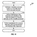
- FIG. 10 shows an embodiment of a process 1000 for performing decision feedback equalization based on a reliability parameter derived from correctly decoded blocks.
- the reliability parameter is estimated based on a first data block that is decoded correctly, which may be determined based on a CRC or some other error detection code (block 1012).
- the reliability parameter may be estimated based on (1) correlation of the transmit chips with the chip estimates, e.g., as shown in equation (43), or (2) an outer product of the transmit symbols and the symbol estimates, e.g., as shown in equation (44).
- the reliability parameter may be filtered across multiple correctly decoded blocks. The time constant for the filtering may be selected based on channel conditions and/or other factors.
- a feed-forward filter response and a feedback filter response are derived based on a channel estimate and the reliability parameter (block 1014). Equalization is performed for a second data block with the feed-forward and feedback filter responses (block 1016). If equalization is performed in multiple iterations or stages, then the reliability parameter may be estimated for each stage based on the first data block and the chip or symbol estimates for that stage. The feed-forward and feedback filter responses for each iteration may be derived based on the reliability parameter for that iteration.
- FIG. 11 shows a block diagram of an embodiment of a transmitter 1110 and a receiver 1150 in a communication system 1100.
- transmitter 1110 is part of a base station
- receiver 1150 is part of a wireless device.
- transmitter 1110 is part of a wireless device
- receiver 1150 is part of a base station.
- a base station is typically a fixed station that communicates with the wireless devices and may also be called a Node B, an access point, and so on.
- a wireless device may be fixed or mobile and may also be called a user equipment (UE), a mobile station, a user terminal, a subscriber unit, and so on.
- UE user equipment
- a wireless device may be a cellular phone, a personal digital assistant (PDA), a wireless modem card, or some other device or apparatus.
- PDA personal digital assistant
- a transmit (TX) data processor 1120 processes (e.g., encodes, interleaves, and symbol maps) traffic data and generates data symbols.
- a data symbol is a modulation symbol for data
- a pilot symbol is a modulation symbol for pilot
- a modulation symbol is a complex value for a point in a signal constellation (e.g., for M-PSK or M-QAM)
- pilot is data that is known a priori by both the transmitter and receiver.
- a modulator 1130 process the data symbols and pilot symbols in a manner specified by the system and provides transmit chips s ( n ) to a transmitter unit (TMTR) 1132.
- Transmitter unit 1132 processes (e.g., converts to analog, amplifies, filters, and frequency upconverts) the transmit chips and generates an RF signal, which is transmitted from an antenna 1134.
- an antenna 1152 receives the transmitted RF signal via various signal paths and provides a received signal to a receiver unit (RCVR) 1154.
- Receiver unit 1154 conditions (e.g., filters, amplifies, and frequency downconverts) the received signal, digitizes the conditioned signal at a sample rate that may be equal to or higher than the chip rate, and provides time-domain input samples.
- An FFT/DFT unit 1156 transforms the input samples to the frequency domain and provides frequency-domain input symbols.
- a channel and noise estimator 1158 estimates the channel response and the noise based on the frequency-domain input symbols and/or the time-domain input samples.
- a decision feedback equalizer (DFE) 1160 derives the feed-forward filter response(s) and the feedback filter response based on the channel and noise estimates and a reliability parameter.
- the reliability parameter may be estimated and updated by DFE 1160, a controller 1190, or some other unit based on correctly decoded blocks and/or other known transmissions.
- DFE 1160 filters the input symbols based on the feed-forward and feedback filter responses and provides chip estimates to a demodulator (Demod) 1170.
- DFE 1160 may implement any of the DFE designs described above.
- Demodulator 1170 processes the chip estimates in a manner complementary to the processing by modulator 1130 and provides data symbol estimates.
- a receive (RX) data processor 1180 processes (e.g., symbol demaps, deinterleaves, and decodes) the data symbol estimates and provides decoded data.
- RX data processor 1180 may also check each data block based on the CRC.
- the processing by demodulator 1170 and RX data processor 1180 is complementary to the processing by modulator 1130 and TX data processor 1120, respectively, at transmitter 1110.
- Controllers/processors 1140 and 1190 direct operation of various processing units at transmitter 1110 and receiver 1150, respectively.
- Memories 1142 and 1192 store data and program codes for transmitter 1110 and receiver 1150, respectively.
- the equalization techniques described herein may be used for various communication systems such as Code Division Multiple Access (CDMA) systems, Time Division Multiple Access (TDMA) systems, Frequency Division Multiple Access (FDMA) systems, Orthogonal FDMA (OFDMA) systems, Single-Carrier FDMA (SC-FDMA) systems, and so on.
- CDMA Code Division Multiple Access
- TDMA Time Division Multiple Access
- FDMA Frequency Division Multiple Access
- OFDMA Orthogonal FDMA
- SC-FDMA Single-Carrier FDMA
- a CDMA system may implement one or more radio technologies such as Wideband-CDMA (W-CDMA), cdma2000, and so on. cdma2000 covers IS-2000, IS-856, and IS-95 standards.
- a TDMA system may implement a radio technology such as Global System for Mobile Communications (GSM). These various radio technologies and standards are known in the art.
- An OFDMA system transmits modulation symbols in the frequency domain on orthogonal sub carriers using orthogonal frequency division
- Modulator 1130 at transmitter 1110 and demodulator 1170 at receiver 1150 perform processing as specified by the system.
- modulator 1130 may perform processing for CDMA, OFDM, SC-FDMA, and so on, or a combination thereof.
- DSP digital signal processor
- ASIC application specific integrated circuit
- FPGA field programmable gate array
- a general-purpose processor may be a microprocessor, but in the alternative, the processor may be any conventional processor, controller, microcontroller, or state machine.
- a processor may also be implemented as a combination of computing devices, e.g., a combination of a DSP and a microprocessor, a plurality of microprocessors, one or more microprocessors in conjunction with a DSP core, or any other such configuration.
- a software module may reside in RAM memory, flash memory, ROM memory, EPROM memory, EEPROM memory, registers, hard disk, a removable disk, a CD-ROM, or any other form of storage medium known in the art.
- An exemplary storage medium is coupled to the processor such that the processor can read information from, and write information to, the storage medium.
- the storage medium may be integral to the processor.
- the processor and the storage medium may reside in an ASIC.
- the ASIC may reside in a user terminal.
- the processor and the storage medium may reside as discrete components in a user terminal.
Landscapes
- Engineering & Computer Science (AREA)
- Power Engineering (AREA)
- Computer Networks & Wireless Communication (AREA)
- Signal Processing (AREA)
- Cable Transmission Systems, Equalization Of Radio And Reduction Of Echo (AREA)
- Filters That Use Time-Delay Elements (AREA)
- Digital Transmission Methods That Use Modulated Carrier Waves (AREA)
Applications Claiming Priority (4)
| Application Number | Priority Date | Filing Date | Title |
|---|---|---|---|
| US66633405P | 2005-03-29 | 2005-03-29 | |
| US66641605P | 2005-03-29 | 2005-03-29 | |
| US11/392,306 US8218615B2 (en) | 2005-03-29 | 2006-03-28 | Method and apparatus for block-wise decision-feedback equalization for wireless communication |
| EP06748941A EP1867119B1 (de) | 2005-03-29 | 2006-03-29 | Verfahren und vorrichtung zur blockweisen, entscheidungsrückgekoppelten entzerrung für drahtlose kommunikationen |
Related Parent Applications (2)
| Application Number | Title | Priority Date | Filing Date |
|---|---|---|---|
| EP06748941A Division EP1867119B1 (de) | 2005-03-29 | 2006-03-29 | Verfahren und vorrichtung zur blockweisen, entscheidungsrückgekoppelten entzerrung für drahtlose kommunikationen |
| EP06748941.9 Division | 2006-03-29 |
Publications (3)
| Publication Number | Publication Date |
|---|---|
| EP2257007A2 true EP2257007A2 (de) | 2010-12-01 |
| EP2257007A3 EP2257007A3 (de) | 2012-02-22 |
| EP2257007B1 EP2257007B1 (de) | 2016-07-20 |
Family
ID=36716242
Family Applications (2)
| Application Number | Title | Priority Date | Filing Date |
|---|---|---|---|
| EP06748941A Expired - Lifetime EP1867119B1 (de) | 2005-03-29 | 2006-03-29 | Verfahren und vorrichtung zur blockweisen, entscheidungsrückgekoppelten entzerrung für drahtlose kommunikationen |
| EP10175637.7A Expired - Lifetime EP2257007B1 (de) | 2005-03-29 | 2006-03-29 | Verfahren und Vorrichtung zur blockweisen Entscheidungs-Feedback-Entzerrung für drahtlose Kommunikation |
Family Applications Before (1)
| Application Number | Title | Priority Date | Filing Date |
|---|---|---|---|
| EP06748941A Expired - Lifetime EP1867119B1 (de) | 2005-03-29 | 2006-03-29 | Verfahren und vorrichtung zur blockweisen, entscheidungsrückgekoppelten entzerrung für drahtlose kommunikationen |
Country Status (6)
| Country | Link |
|---|---|
| US (1) | US8218615B2 (de) |
| EP (2) | EP1867119B1 (de) |
| JP (2) | JP4902639B2 (de) |
| KR (1) | KR100956045B1 (de) |
| CN (1) | CN101185301B (de) |
| WO (1) | WO2006105309A1 (de) |
Families Citing this family (17)
| Publication number | Priority date | Publication date | Assignee | Title |
|---|---|---|---|---|
| KR100555520B1 (ko) * | 2003-10-28 | 2006-03-03 | 삼성전자주식회사 | 다중 캐리어 신호의 비선형적 왜곡을 보상하는 다중캐리어 신호 왜곡 보상 장치, 이를 구비한 다중 캐리어신호 수신기, 및 그 방법 |
| US8218615B2 (en) | 2005-03-29 | 2012-07-10 | Qualcomm Incorporated | Method and apparatus for block-wise decision-feedback equalization for wireless communication |
| US8615035B2 (en) | 2005-03-29 | 2013-12-24 | Qualcomm Incorporated | Method and apparatus for block-wise decision-feedback equalization for wireless communication |
| KR101100199B1 (ko) * | 2005-05-02 | 2011-12-28 | 엘지전자 주식회사 | Ifdma 시스템의 대역 제한 방법 |
| KR20130108464A (ko) | 2005-09-29 | 2013-10-02 | 인터디지탈 테크날러지 코포레이션 | Mimo 빔형성 기반의 단일 반송파 주파수 분할 다중 접속 시스템 |
| US8488726B2 (en) * | 2006-08-02 | 2013-07-16 | Clariphy Communications, Inc. | Receivers based on closed-form parametric estimates of the probability density function for the received signal |
| US8155218B2 (en) * | 2007-03-17 | 2012-04-10 | Qualcomm Incorporated | Frequency domain equalization for time varying channels |
| KR101408866B1 (ko) * | 2007-09-03 | 2014-06-17 | 삼성전자주식회사 | 단일반송파 주파수분할 다중접속방식의 다중입출력시스템에서 신호 검출 방법 및 장치 |
| TWI416955B (zh) * | 2008-11-24 | 2013-11-21 | Realtek Semiconductor Corp | 單載波/多載波共用接收器以及處理單載波/多載波共用接收器所接收之接收訊號的方法 |
| GB2472102B (en) * | 2009-07-24 | 2015-05-20 | Cambridge Consultants | Receiver for wireless transmission |
| US9084276B2 (en) * | 2009-09-11 | 2015-07-14 | Aerovironment, Inc. | Dynamic transmission control for a wireless network |
| US8494035B2 (en) | 2011-03-18 | 2013-07-23 | Imec | Frequency-domain adaptive feedback equalizer |
| GB2503073B (en) | 2013-03-27 | 2014-04-23 | Imagination Tech Ltd | Efficient tracking of decision-feedback equaliser coefficients |
| TWI575901B (zh) * | 2015-06-17 | 2017-03-21 | 晨星半導體股份有限公司 | 通道效應消除裝置及通道效應消除方法 |
| TWI646785B (zh) * | 2017-09-29 | 2019-01-01 | 晨星半導體股份有限公司 | 無線通訊系統及其信號處理方法 |
| TWI694683B (zh) * | 2019-12-17 | 2020-05-21 | 瑞昱半導體股份有限公司 | 應用於高速有線網路的資料傳輸裝置及方法 |
| CN112714085B (zh) * | 2020-12-11 | 2022-06-28 | 硅谷数模(苏州)半导体有限公司 | 判决反馈均衡电路 |
Family Cites Families (31)
| Publication number | Priority date | Publication date | Assignee | Title |
|---|---|---|---|---|
| US5178696A (en) | 1990-09-03 | 1993-01-12 | Nippon Kayaku Kabushiki Kaisha | Gas generating composition for automobile air bag |
| JPH05284063A (ja) | 1992-03-30 | 1993-10-29 | Idou Tsushin Syst Kaihatsu Kk | 自動等化器 |
| US5513215A (en) * | 1993-09-20 | 1996-04-30 | Glenayre Electronics, Inc. | High speed simulcast data system using adaptive compensation |
| US5499272A (en) | 1994-05-31 | 1996-03-12 | Ericsson Ge Mobile Communications Inc. | Diversity receiver for signals with multipath time dispersion |
| US5970093A (en) * | 1996-01-23 | 1999-10-19 | Tiernan Communications, Inc. | Fractionally-spaced adaptively-equalized self-recovering digital receiver for amplitude-Phase modulated signals |
| DE19602612A1 (de) | 1996-01-25 | 1997-07-31 | Bosch Gmbh Robert | Telekommunikationsendgerät mit optischer Signalisiervorrichtung |
| US5930296A (en) * | 1997-04-08 | 1999-07-27 | Glenayre Electronics, Inc. | Low-complexity bidirectional equalizer |
| JPH11261457A (ja) | 1998-03-10 | 1999-09-24 | Hitachi Ltd | 波形等化処理方法 |
| JP2000068910A (ja) | 1998-08-18 | 2000-03-03 | Kokusai Electric Co Ltd | ダイバーシチ受信装置 |
| FR2789243B1 (fr) | 1999-01-29 | 2001-05-25 | France Telecom | Egaliseur a retour de decisions ponderees, et procede d'egalisation correspondant |
| US20020106040A1 (en) * | 2001-02-02 | 2002-08-08 | Sarnoff Corporation | Method and apparatus for reducing multipath distortion in a wireless ian system |
| JP3735015B2 (ja) | 2000-07-26 | 2006-01-11 | 松下電器産業株式会社 | 回線推定装置および回線推定方法 |
| JP3970764B2 (ja) | 2000-10-17 | 2007-09-05 | コーニンクレッカ フィリップス エレクトロニクス エヌ ヴィ | マルチスタンダードチャンネル復号器 |
| US6829297B2 (en) | 2001-06-06 | 2004-12-07 | Micronas Semiconductors, Inc. | Adaptive equalizer having a variable step size influenced by output from a trellis decoder |
| US7113540B2 (en) * | 2001-09-18 | 2006-09-26 | Broadcom Corporation | Fast computation of multi-input-multi-output decision feedback equalizer coefficients |
| US7263123B2 (en) * | 2001-09-18 | 2007-08-28 | Broadcom Corporation | Fast computation of coefficients for a variable delay decision feedback equalizer |
| KR100416265B1 (ko) | 2001-12-11 | 2004-01-24 | 삼성전자주식회사 | 출력신호의 부호와 절대값을 이용하여 그 동작을 제어하는적응형 등화기 |
| US7046726B2 (en) | 2002-07-18 | 2006-05-16 | Qualcomm, Inc. | Method and apparatus for hybrid decision feedback equalization |
| EP2254295B1 (de) | 2002-07-18 | 2011-10-05 | Qualcomm Incorporated | Verfahren zur Entscheidungsrückgekoppelten Entzerrerung |
| GB2392067B (en) | 2002-08-16 | 2005-04-06 | Toshiba Res Europ Ltd | Channel estimation apparatus and methods |
| CN1238977C (zh) * | 2002-11-01 | 2006-01-25 | 上海奇普科技有限公司 | 一种可变步长受网格解码器输出影响的自适应均衡器 |
| US7313182B2 (en) * | 2003-03-24 | 2007-12-25 | Zenith Electronics Corporation | Decision feedback equalizers with constrained feedback taps for reduced error propagation |
| TWI224451B (en) | 2003-06-20 | 2004-11-21 | Via Tech Inc | Receiver with decision feedback equalizer and decision sequence generation method thereof |
| US20050018794A1 (en) * | 2003-07-22 | 2005-01-27 | Xiangguo Tang | High speed, low-cost process for the demodulation and detection in EDGE wireless cellular systems |
| TWI229511B (en) | 2003-09-19 | 2005-03-11 | Via Tech Inc | Method for updating coefficients in decision feedback equalizer |
| US20050232347A1 (en) * | 2004-04-15 | 2005-10-20 | Mediatek Incorporation | Apparatus and method for noise enhancement reduction in an adaptive equalizer |
| US7502412B2 (en) * | 2004-05-20 | 2009-03-10 | Qisda Corporation | Adaptive channel estimation using decision feedback |
| JP4934035B2 (ja) | 2004-06-09 | 2012-05-16 | イー・アイ・デュポン・ドウ・ヌムール・アンド・カンパニー | 有機金属化合物およびかかる化合物で形成された素子 |
| KR100698630B1 (ko) * | 2004-06-28 | 2007-03-21 | 삼성전자주식회사 | 스텝사이즈 조정기능을 구비한 등화기 및 등화방법 |
| US8218615B2 (en) | 2005-03-29 | 2012-07-10 | Qualcomm Incorporated | Method and apparatus for block-wise decision-feedback equalization for wireless communication |
| JP2010279315A (ja) | 2009-06-08 | 2010-12-16 | Iseki & Co Ltd | コンバイン |
-
2006
- 2006-03-28 US US11/392,306 patent/US8218615B2/en not_active Expired - Fee Related
- 2006-03-29 WO PCT/US2006/011670 patent/WO2006105309A1/en not_active Ceased
- 2006-03-29 EP EP06748941A patent/EP1867119B1/de not_active Expired - Lifetime
- 2006-03-29 EP EP10175637.7A patent/EP2257007B1/de not_active Expired - Lifetime
- 2006-03-29 JP JP2008504371A patent/JP4902639B2/ja not_active Expired - Fee Related
- 2006-03-29 CN CN200680018352.3A patent/CN101185301B/zh not_active Expired - Fee Related
- 2006-03-29 KR KR1020077024904A patent/KR100956045B1/ko not_active Expired - Fee Related
-
2010
- 2010-12-15 JP JP2010279315A patent/JP4902781B2/ja not_active Expired - Fee Related
Also Published As
| Publication number | Publication date |
|---|---|
| CN101185301B (zh) | 2015-08-12 |
| WO2006105309A1 (en) | 2006-10-05 |
| KR20070119054A (ko) | 2007-12-18 |
| EP1867119B1 (de) | 2012-08-01 |
| KR100956045B1 (ko) | 2010-05-06 |
| EP2257007A3 (de) | 2012-02-22 |
| CN101185301A (zh) | 2008-05-21 |
| JP2008536386A (ja) | 2008-09-04 |
| JP4902639B2 (ja) | 2012-03-21 |
| US20060227859A1 (en) | 2006-10-12 |
| EP1867119A1 (de) | 2007-12-19 |
| JP4902781B2 (ja) | 2012-03-21 |
| EP2257007B1 (de) | 2016-07-20 |
| US8218615B2 (en) | 2012-07-10 |
| JP2011103673A (ja) | 2011-05-26 |
Similar Documents
| Publication | Publication Date | Title |
|---|---|---|
| JP4902781B2 (ja) | 無線通信用のブロック単位判定帰還形等化の方法及び装置 | |
| CA2584442C (en) | Log-likelihood estimation based on channel estimation errors due to guard subbands | |
| US8102907B2 (en) | Space-frequency equalization for oversampled received signals | |
| US20060280257A1 (en) | Method and apparatus for generating weights for transmit diversity in wireless communication | |
| EP1847085A1 (de) | Auswahl eines schwellenparameters zur kanalschätzung | |
| US7388935B2 (en) | Method of inverting nearly Toeplitz or block Toeplitz matrices | |
| US8615035B2 (en) | Method and apparatus for block-wise decision-feedback equalization for wireless communication | |
| US6724841B2 (en) | Equalizer with a cost function taking into account noise energy | |
| EP1849276B1 (de) | Verfahren und system zur kanalentzerrung | |
| US8867600B2 (en) | Turbo equalization for diversity receivers | |
| HK1115025A (en) | Method and apparatus for block-wise decision-feedback equalization for wireless communication | |
| EP1925090B1 (de) | Drahtloses kommunikationsgerät mit einem verbund-raum-zeit-optimalfilter (jstof) mit qr- und eigenwertzerlegungen | |
| CN101199125B (zh) | 用于干扰消除的联合空时最优滤波器(jstof) | |
| CN101283514A (zh) | 用于干扰抵消的联合空时最优滤波器 | |
| CN101283516A (zh) | 包括使用乔列斯基和特征值分解的联合空时最优滤波器的无线通信设备 | |
| EP1922817B1 (de) | Drahtloses kommunikationsgerät mit verbund-raum-zeit-optimalfiltern (jstof) mit singulärwertzerlegungen (svd) | |
| JP2009505523A (ja) | 干渉の除去のための統合型時空間最適フィルタ(jstof) | |
| CN101283611A (zh) | 具有至少一个天线、至少一个信道和联合滤波器权重-信道冲激响应估计的联合空时最优滤波器 | |
| HK1118395A (en) | Method and apparatus for generating weights for transmit diversity in wireless communication |
Legal Events
| Date | Code | Title | Description |
|---|---|---|---|
| PUAI | Public reference made under article 153(3) epc to a published international application that has entered the european phase |
Free format text: ORIGINAL CODE: 0009012 |
|
| AC | Divisional application: reference to earlier application |
Ref document number: 1867119 Country of ref document: EP Kind code of ref document: P |
|
| AK | Designated contracting states |
Kind code of ref document: A2 Designated state(s): AT BE BG CH CY CZ DE DK EE ES FI FR GB GR HU IE IS IT LI LT LU LV MC NL PL PT RO SE SI SK TR |
|
| PUAL | Search report despatched |
Free format text: ORIGINAL CODE: 0009013 |
|
| AK | Designated contracting states |
Kind code of ref document: A3 Designated state(s): AT BE BG CH CY CZ DE DK EE ES FI FR GB GR HU IE IS IT LI LT LU LV MC NL PL PT RO SE SI SK TR |
|
| RIC1 | Information provided on ipc code assigned before grant |
Ipc: H04L 25/03 20060101AFI20120117BHEP |
|
| 17P | Request for examination filed |
Effective date: 20120726 |
|
| 17Q | First examination report despatched |
Effective date: 20130110 |
|
| GRAP | Despatch of communication of intention to grant a patent |
Free format text: ORIGINAL CODE: EPIDOSNIGR1 |
|
| INTG | Intention to grant announced |
Effective date: 20160208 |
|
| GRAS | Grant fee paid |
Free format text: ORIGINAL CODE: EPIDOSNIGR3 |
|
| GRAA | (expected) grant |
Free format text: ORIGINAL CODE: 0009210 |
|
| AC | Divisional application: reference to earlier application |
Ref document number: 1867119 Country of ref document: EP Kind code of ref document: P |
|
| AK | Designated contracting states |
Kind code of ref document: B1 Designated state(s): AT BE BG CH CY CZ DE DK EE ES FI FR GB GR HU IE IS IT LI LT LU LV MC NL PL PT RO SE SI SK TR |
|
| REG | Reference to a national code |
Ref country code: GB Ref legal event code: FG4D |
|
| REG | Reference to a national code |
Ref country code: CH Ref legal event code: EP |
|
| REG | Reference to a national code |
Ref country code: IE Ref legal event code: FG4D |
|
| REG | Reference to a national code |
Ref country code: AT Ref legal event code: REF Ref document number: 814865 Country of ref document: AT Kind code of ref document: T Effective date: 20160815 |
|
| REG | Reference to a national code |
Ref country code: DE Ref legal event code: R096 Ref document number: 602006049693 Country of ref document: DE |
|
| REG | Reference to a national code |
Ref country code: LT Ref legal event code: MG4D |
|
| REG | Reference to a national code |
Ref country code: NL Ref legal event code: MP Effective date: 20160720 |
|
| REG | Reference to a national code |
Ref country code: AT Ref legal event code: MK05 Ref document number: 814865 Country of ref document: AT Kind code of ref document: T Effective date: 20160720 |
|
| PG25 | Lapsed in a contracting state [announced via postgrant information from national office to epo] |
Ref country code: IT Free format text: LAPSE BECAUSE OF FAILURE TO SUBMIT A TRANSLATION OF THE DESCRIPTION OR TO PAY THE FEE WITHIN THE PRESCRIBED TIME-LIMIT Effective date: 20160720 Ref country code: NL Free format text: LAPSE BECAUSE OF FAILURE TO SUBMIT A TRANSLATION OF THE DESCRIPTION OR TO PAY THE FEE WITHIN THE PRESCRIBED TIME-LIMIT Effective date: 20160720 Ref country code: LT Free format text: LAPSE BECAUSE OF FAILURE TO SUBMIT A TRANSLATION OF THE DESCRIPTION OR TO PAY THE FEE WITHIN THE PRESCRIBED TIME-LIMIT Effective date: 20160720 Ref country code: IS Free format text: LAPSE BECAUSE OF FAILURE TO SUBMIT A TRANSLATION OF THE DESCRIPTION OR TO PAY THE FEE WITHIN THE PRESCRIBED TIME-LIMIT Effective date: 20161120 Ref country code: FI Free format text: LAPSE BECAUSE OF FAILURE TO SUBMIT A TRANSLATION OF THE DESCRIPTION OR TO PAY THE FEE WITHIN THE PRESCRIBED TIME-LIMIT Effective date: 20160720 |
|
| PG25 | Lapsed in a contracting state [announced via postgrant information from national office to epo] |
Ref country code: SE Free format text: LAPSE BECAUSE OF FAILURE TO SUBMIT A TRANSLATION OF THE DESCRIPTION OR TO PAY THE FEE WITHIN THE PRESCRIBED TIME-LIMIT Effective date: 20160720 Ref country code: GR Free format text: LAPSE BECAUSE OF FAILURE TO SUBMIT A TRANSLATION OF THE DESCRIPTION OR TO PAY THE FEE WITHIN THE PRESCRIBED TIME-LIMIT Effective date: 20161021 Ref country code: BE Free format text: LAPSE BECAUSE OF FAILURE TO SUBMIT A TRANSLATION OF THE DESCRIPTION OR TO PAY THE FEE WITHIN THE PRESCRIBED TIME-LIMIT Effective date: 20160720 Ref country code: AT Free format text: LAPSE BECAUSE OF FAILURE TO SUBMIT A TRANSLATION OF THE DESCRIPTION OR TO PAY THE FEE WITHIN THE PRESCRIBED TIME-LIMIT Effective date: 20160720 Ref country code: LV Free format text: LAPSE BECAUSE OF FAILURE TO SUBMIT A TRANSLATION OF THE DESCRIPTION OR TO PAY THE FEE WITHIN THE PRESCRIBED TIME-LIMIT Effective date: 20160720 Ref country code: PL Free format text: LAPSE BECAUSE OF FAILURE TO SUBMIT A TRANSLATION OF THE DESCRIPTION OR TO PAY THE FEE WITHIN THE PRESCRIBED TIME-LIMIT Effective date: 20160720 Ref country code: ES Free format text: LAPSE BECAUSE OF FAILURE TO SUBMIT A TRANSLATION OF THE DESCRIPTION OR TO PAY THE FEE WITHIN THE PRESCRIBED TIME-LIMIT Effective date: 20160720 Ref country code: PT Free format text: LAPSE BECAUSE OF FAILURE TO SUBMIT A TRANSLATION OF THE DESCRIPTION OR TO PAY THE FEE WITHIN THE PRESCRIBED TIME-LIMIT Effective date: 20161121 |
|
| REG | Reference to a national code |
Ref country code: DE Ref legal event code: R097 Ref document number: 602006049693 Country of ref document: DE |
|
| PG25 | Lapsed in a contracting state [announced via postgrant information from national office to epo] |
Ref country code: RO Free format text: LAPSE BECAUSE OF FAILURE TO SUBMIT A TRANSLATION OF THE DESCRIPTION OR TO PAY THE FEE WITHIN THE PRESCRIBED TIME-LIMIT Effective date: 20160720 Ref country code: EE Free format text: LAPSE BECAUSE OF FAILURE TO SUBMIT A TRANSLATION OF THE DESCRIPTION OR TO PAY THE FEE WITHIN THE PRESCRIBED TIME-LIMIT Effective date: 20160720 |
|
| PLBE | No opposition filed within time limit |
Free format text: ORIGINAL CODE: 0009261 |
|
| STAA | Information on the status of an ep patent application or granted ep patent |
Free format text: STATUS: NO OPPOSITION FILED WITHIN TIME LIMIT |
|
| PG25 | Lapsed in a contracting state [announced via postgrant information from national office to epo] |
Ref country code: BG Free format text: LAPSE BECAUSE OF FAILURE TO SUBMIT A TRANSLATION OF THE DESCRIPTION OR TO PAY THE FEE WITHIN THE PRESCRIBED TIME-LIMIT Effective date: 20161020 Ref country code: SK Free format text: LAPSE BECAUSE OF FAILURE TO SUBMIT A TRANSLATION OF THE DESCRIPTION OR TO PAY THE FEE WITHIN THE PRESCRIBED TIME-LIMIT Effective date: 20160720 Ref country code: CZ Free format text: LAPSE BECAUSE OF FAILURE TO SUBMIT A TRANSLATION OF THE DESCRIPTION OR TO PAY THE FEE WITHIN THE PRESCRIBED TIME-LIMIT Effective date: 20160720 Ref country code: DK Free format text: LAPSE BECAUSE OF FAILURE TO SUBMIT A TRANSLATION OF THE DESCRIPTION OR TO PAY THE FEE WITHIN THE PRESCRIBED TIME-LIMIT Effective date: 20160720 |
|
| 26N | No opposition filed |
Effective date: 20170421 |
|
| PG25 | Lapsed in a contracting state [announced via postgrant information from national office to epo] |
Ref country code: SI Free format text: LAPSE BECAUSE OF FAILURE TO SUBMIT A TRANSLATION OF THE DESCRIPTION OR TO PAY THE FEE WITHIN THE PRESCRIBED TIME-LIMIT Effective date: 20160720 |
|
| REG | Reference to a national code |
Ref country code: CH Ref legal event code: PL |
|
| PG25 | Lapsed in a contracting state [announced via postgrant information from national office to epo] |
Ref country code: MC Free format text: LAPSE BECAUSE OF FAILURE TO SUBMIT A TRANSLATION OF THE DESCRIPTION OR TO PAY THE FEE WITHIN THE PRESCRIBED TIME-LIMIT Effective date: 20160720 |
|
| REG | Reference to a national code |
Ref country code: IE Ref legal event code: MM4A |
|
| REG | Reference to a national code |
Ref country code: FR Ref legal event code: ST Effective date: 20171130 |
|
| PG25 | Lapsed in a contracting state [announced via postgrant information from national office to epo] |
Ref country code: FR Free format text: LAPSE BECAUSE OF NON-PAYMENT OF DUE FEES Effective date: 20170331 Ref country code: LU Free format text: LAPSE BECAUSE OF NON-PAYMENT OF DUE FEES Effective date: 20170329 |
|
| PG25 | Lapsed in a contracting state [announced via postgrant information from national office to epo] |
Ref country code: IE Free format text: LAPSE BECAUSE OF NON-PAYMENT OF DUE FEES Effective date: 20170329 Ref country code: LI Free format text: LAPSE BECAUSE OF NON-PAYMENT OF DUE FEES Effective date: 20170331 Ref country code: CH Free format text: LAPSE BECAUSE OF NON-PAYMENT OF DUE FEES Effective date: 20170331 |
|
| PG25 | Lapsed in a contracting state [announced via postgrant information from national office to epo] |
Ref country code: HU Free format text: LAPSE BECAUSE OF FAILURE TO SUBMIT A TRANSLATION OF THE DESCRIPTION OR TO PAY THE FEE WITHIN THE PRESCRIBED TIME-LIMIT; INVALID AB INITIO Effective date: 20060329 |
|
| PG25 | Lapsed in a contracting state [announced via postgrant information from national office to epo] |
Ref country code: CY Free format text: LAPSE BECAUSE OF NON-PAYMENT OF DUE FEES Effective date: 20160720 |
|
| PG25 | Lapsed in a contracting state [announced via postgrant information from national office to epo] |
Ref country code: TR Free format text: LAPSE BECAUSE OF FAILURE TO SUBMIT A TRANSLATION OF THE DESCRIPTION OR TO PAY THE FEE WITHIN THE PRESCRIBED TIME-LIMIT Effective date: 20160720 |
|
| PGFP | Annual fee paid to national office [announced via postgrant information from national office to epo] |
Ref country code: GB Payment date: 20200228 Year of fee payment: 15 Ref country code: DE Payment date: 20200214 Year of fee payment: 15 |
|
| REG | Reference to a national code |
Ref country code: DE Ref legal event code: R082 Ref document number: 602006049693 Country of ref document: DE Representative=s name: MAUCHER JENKINS PATENTANWAELTE & RECHTSANWAELT, DE |
|
| REG | Reference to a national code |
Ref country code: DE Ref legal event code: R119 Ref document number: 602006049693 Country of ref document: DE |
|
| GBPC | Gb: european patent ceased through non-payment of renewal fee |
Effective date: 20210329 |
|
| PG25 | Lapsed in a contracting state [announced via postgrant information from national office to epo] |
Ref country code: GB Free format text: LAPSE BECAUSE OF NON-PAYMENT OF DUE FEES Effective date: 20210329 Ref country code: DE Free format text: LAPSE BECAUSE OF NON-PAYMENT OF DUE FEES Effective date: 20211001 |