EP2258003B1 - Appareil electromenager comportant une pompe piezo-electrique munie d'un circuit d'alimentation electrique simplifie - Google Patents
Appareil electromenager comportant une pompe piezo-electrique munie d'un circuit d'alimentation electrique simplifie Download PDFInfo
- Publication number
- EP2258003B1 EP2258003B1 EP09734486.5A EP09734486A EP2258003B1 EP 2258003 B1 EP2258003 B1 EP 2258003B1 EP 09734486 A EP09734486 A EP 09734486A EP 2258003 B1 EP2258003 B1 EP 2258003B1
- Authority
- EP
- European Patent Office
- Prior art keywords
- pump
- circuit
- piezoelectric
- supply circuit
- power supply
- Prior art date
- Legal status (The legal status is an assumption and is not a legal conclusion. Google has not performed a legal analysis and makes no representation as to the accuracy of the status listed.)
- Not-in-force
Links
- 239000012528 membrane Substances 0.000 description 8
- XEEYBQQBJWHFJM-UHFFFAOYSA-N Iron Chemical compound [Fe] XEEYBQQBJWHFJM-UHFFFAOYSA-N 0.000 description 6
- XLYOFNOQVPJJNP-UHFFFAOYSA-N water Substances O XLYOFNOQVPJJNP-UHFFFAOYSA-N 0.000 description 4
- 229910052742 iron Inorganic materials 0.000 description 3
- 230000004048 modification Effects 0.000 description 3
- 238000012986 modification Methods 0.000 description 3
- 230000008016 vaporization Effects 0.000 description 3
- 238000009834 vaporization Methods 0.000 description 3
- 239000000919 ceramic Substances 0.000 description 2
- 238000010438 heat treatment Methods 0.000 description 2
- UKGJZDSUJSPAJL-YPUOHESYSA-N (e)-n-[(1r)-1-[3,5-difluoro-4-(methanesulfonamido)phenyl]ethyl]-3-[2-propyl-6-(trifluoromethyl)pyridin-3-yl]prop-2-enamide Chemical compound CCCC1=NC(C(F)(F)F)=CC=C1\C=C\C(=O)N[C@H](C)C1=CC(F)=C(NS(C)(=O)=O)C(F)=C1 UKGJZDSUJSPAJL-YPUOHESYSA-N 0.000 description 1
- 229910001369 Brass Inorganic materials 0.000 description 1
- 239000010951 brass Substances 0.000 description 1
- 239000003990 capacitor Substances 0.000 description 1
- 230000006378 damage Effects 0.000 description 1
- 238000009792 diffusion process Methods 0.000 description 1
- 230000000694 effects Effects 0.000 description 1
- 235000000396 iron Nutrition 0.000 description 1
- 244000045947 parasite Species 0.000 description 1
- 238000006467 substitution reaction Methods 0.000 description 1
- 230000008646 thermal stress Effects 0.000 description 1
- 230000009466 transformation Effects 0.000 description 1
Images

Classifications
-
- H—ELECTRICITY
- H10—SEMICONDUCTOR DEVICES; ELECTRIC SOLID-STATE DEVICES NOT OTHERWISE PROVIDED FOR
- H10N—ELECTRIC SOLID-STATE DEVICES NOT OTHERWISE PROVIDED FOR
- H10N30/00—Piezoelectric or electrostrictive devices
- H10N30/80—Constructional details
- H10N30/802—Circuitry or processes for operating piezoelectric or electrostrictive devices not otherwise provided for, e.g. drive circuits
-
- D—TEXTILES; PAPER
- D06—TREATMENT OF TEXTILES OR THE LIKE; LAUNDERING; FLEXIBLE MATERIALS NOT OTHERWISE PROVIDED FOR
- D06F—LAUNDERING, DRYING, IRONING, PRESSING OR FOLDING TEXTILE ARTICLES
- D06F75/00—Hand irons
- D06F75/08—Hand irons internally heated by electricity
- D06F75/10—Hand irons internally heated by electricity with means for supplying steam to the article being ironed
- D06F75/14—Hand irons internally heated by electricity with means for supplying steam to the article being ironed the steam being produced from water in a reservoir carried by the iron
-
- F—MECHANICAL ENGINEERING; LIGHTING; HEATING; WEAPONS; BLASTING
- F04—POSITIVE - DISPLACEMENT MACHINES FOR LIQUIDS; PUMPS FOR LIQUIDS OR ELASTIC FLUIDS
- F04B—POSITIVE-DISPLACEMENT MACHINES FOR LIQUIDS; PUMPS
- F04B43/00—Machines, pumps, or pumping installations having flexible working members
- F04B43/02—Machines, pumps, or pumping installations having flexible working members having plate-like flexible members, e.g. diaphragms
- F04B43/04—Pumps having electric drive
- F04B43/043—Micropumps
- F04B43/046—Micropumps with piezoelectric drive
Definitions
- the present invention relates to an appliance with a piezoelectric pump provided with a power supply circuit.
- the piezoelectric pump generally comprises a chamber having a flexible membrane on which is fixed a piezoelectric element.
- the chamber comprises a supply duct and an outlet duct both comprising an anti-return valve.
- the piezoelectric element will vibrate at the frequency of an AC voltage supplied by a supply circuit and with an amplitude controlled by this voltage, thus generating a succession of suction and discharge cycles.
- Power supply circuits of such a piezoelectric pump comprising a complex electronics which, from the available voltage of the electrical network or a battery, recreates a frequency and shape signal adapted to oscillate the piezoelectric element of the pump.
- This type of power circuit has the disadvantage of implementing expensive and numerous electronic components, source of potential failures.
- the object of the present invention is to overcome the aforementioned drawbacks and to provide a household appliance equipped with a piezoelectric pump whose supply circuit, from the electrical network, is simple and economical to implement.
- Another object of the invention is to propose a household appliance equipped with a piezoelectric pump whose feed circuit presents a great reliability and safe operation.
- Another object of the invention is to provide a household appliance equipped with a piezoelectric pump whose feed circuit ensures a regular flow rate provided by the pump
- electrical network refers to the domestic electrical network supplying an alternating voltage type current, depending on the country in which it is located, between 100 volts and 240 volts and with a frequency of between 50 hertz and 60 hertz.
- the supply circuit applies a voltage whose frequency comes directly from the electrical network, without modification or transformation, which makes it possible to obtain a very simple circuit.
- the circuit comprises means for limiting the current absorbed by the pump arranged in series. This arrangement makes it possible to protect the pump and to ensure reliable operation in particular conditions of the network connection type, idle operation or interference on the network.
- the means for limiting the current absorbed by the pump comprise a resistor.
- This arrangement makes it possible to obtain a very simple and very economical supply circuit.
- the circuit comprises at least one resistor in parallel with the pump.
- This arrangement makes it possible to protect the pump and to ensure reliable operation when the power supply to the pump is cut off.
- the circuit comprises means for limiting the voltage across the pump, arranged in parallel with said pump.
- This arrangement makes it possible to overcome fluctuations in the network and variations in the physical characteristics of the piezoelectric element (such as, for example, capacitance) and thus obtain a regular flow rate of the pump.
- the means for limiting the voltage across the pump arranged in parallel with said pump comprise at least two Zener diodes.
- the invention also relates to a household appliance comprising a piezoelectric pump and a supply circuit of said pump, characterized in that said supply circuit is in accordance with the invention.
- This arrangement makes it possible to optimize the cost of such an apparatus by means of a very economical supply circuit.
- JP 61-58286 Known feed circuits are disclosed by JP 61-58286 .
- the apparatus according to the invention is an iron 1 comprising a piezoelectric pump 10 which makes it possible to transfer water from a tank 3 to a vaporization chamber 4 included in a heating soleplate 5 provided with vapor diffusion openings.
- the piezoelectric pump 10 comprises a circular chamber 11 comprising a bottom wall formed by a flexible membrane 12 made of brass.
- a piezoelectric element 13 made of ceramic is fixed on the membrane 12, outside the circular chamber 11.
- the circular chamber 11 comprises an upper wall provided with an intake duct 14 connected to the reservoir 3 and a exhaust duct 15 connected to the vaporization chamber 4.
- the piezoelectric pump 10 comprises a power supply terminal 18 fixed on the membrane 12 and a power supply terminal 19 fixed on the piezoelectric element 13.
- the pump 10 is supplied at its terminals 18, 19 by a alternating voltage.
- the piezoelectric element 13 deforms, driving the membrane 12, so as to increase the volume of the circular chamber 11.
- the exhaust duct 15 comprises an anti-return valve 17 which closes and prevents the suction of water present downstream of the valve 17.
- the intake duct 14 also comprises a non-return valve 16 which opens and thus allows the water present in the intake duct 14, from the tank 3 ( Fig. 1 ), to be sucked into the circular chamber 11.
- the piezoelectric element 13 deforms, driving the membrane 12, so as to reduce the volume of the circular chamber 11.
- the valve 16 of the intake duct 14 closes and in the at the same time, the valve 17 of the exhaust duct 15 opens.
- the water will pass from the circular chamber 11 to the vaporization chamber 4 ( Fig. 1 ).
- the piezoelectric element 13 and the membrane 12 form a piezoelectric actuator chosen from commercial models, manufactured in large series.
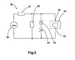
- the piezoelectric pump 10 is supplied by a supply circuit 20 from an electrical network 25 delivering an alternating voltage, for example 230 volts, at a frequency, for example 50 hertz, this frequency being applied without modification to the terminals 18, 19 of the pump 10.
- an electrical network 25 delivering an alternating voltage, for example 230 volts, at a frequency, for example 50 hertz, this frequency being applied without modification to the terminals 18, 19 of the pump 10.
- the supply circuit 20 comprises a resistor 21, arranged in series with the pump 10, which makes it possible to limit the current absorbed by the pump 10 in the various critical phases of operation that can occur during the use of the apparatus 1 and which helps to protect the piezoelectric element 13.
- the piezoelectric actuator which is comparable to a capacitance, is first of all equivalent to a short circuit which calls for a peak of current.
- the peak current is all the higher as the power up occurs at a voltage level near the top of the alternation.
- a second critical phase also occurs when the pump 10 is energized while its circular chamber 11 is empty (this type of operation is called "dry or dry operation"), the piezoelectric actuator heats up. This has the effect of changing its capacity and increase the current it consumes. The increase in the current consumed accelerates the heating and the phenomenon is accelerated until the destruction of the piezoelectric element 13.
- the current peak or peaks are parasites brought by the electrical network.
- the supply circuit 20 also comprises a resistor 22 arranged in parallel with the pump 10.
- This resistor 22 makes it possible to discharge the piezoelectric actuator, electrically equivalent to a capacitor, after the power supply has been cut off, and also protects the piezoelectric actuator against overcurrent when reconnected to the electrical network 25.
- the piezoelectric actuator comprises a piezoelectric element 13 made of ceramic and a flexible membrane 12, both having a thickness of between 0.005 and 1 millimeter, preferably 0.3 millimeter.
- Resistor 21 has a value between 1 and 100 kilo ohms, preferably 15 kilo ohms, and resistor 22 has a value between 100 and 2000 kilo ohms, preferably 1000 kilo ohms.
- the supply circuit 20 also comprises two Zener diodes 23, 24 arranged head to tail in parallel with the pump 10.
- These Zener diodes 23, 24 make it possible to limit the voltage at the terminals 18, 19 of the pump. diode for the positive half cycle and the other diode for the negative half cycle. Thus, it avoids fluctuations in the voltage delivered by the electrical network to ensure a regularity of the flow rate provided by the pump 10.
- the diodes 23 , 24 clings the voltage to a value between 80 and 200 volts, preferably 180 volts.
- the resistors 21, 22 lower the maximum value of the signal at the terminals of the pump 10 and the Zener diodes 23, 24 will clip the same signal but the Frequency is the same as the frequency of the power grid.
- the iron 1 ( Fig. 1 ) comprises a handle 6.
- the supply circuit (not shown in FIG. Fig. 1 ) is arranged in the handle 6 to avoid thermal stress on this supply circuit.
- a capacitance type impedance can be added to the resistor disposed in series with the pump to limit the absorbed current.
Landscapes
- Engineering & Computer Science (AREA)
- Mechanical Engineering (AREA)
- General Engineering & Computer Science (AREA)
- Textile Engineering (AREA)
- Reciprocating Pumps (AREA)
Description
- La présente invention concerne un appareil électroménager équipé d'une pompe piézo-électrique munie d'un circuit d'alimentation électrique.
- Dans le domaine des appareils du type précité, la pompe piézo-électrique comporte généralement une chambre présentant une membrane souple sur laquelle est fixé un élément piézo-électrique. La chambre comporte un conduit d'amenée et un conduit de sortie comprenant tous deux un clapet anti retour.
- En fonctionnement, l'élément piézo-électrique va vibrer à la fréquence d'une tension alternative fournie par un circuit d'alimentation et avec une amplitude pilotée par cette tension, générant ainsi une succession de cycles d'aspiration et de refoulement.
- On connaît des circuits d'alimentation d'une telle pompe piézo-électrique, comportant une électronique complexe qui, à partir de la tension disponible du réseau électrique ou d'une batterie, recrée un signal de fréquence et de forme adapté pour faire osciller l'élément piézo-électrique de la pompe.
- Ce type de circuits d'alimentation présente l'inconvénient de mettre en oeuvre des composants électroniques chers et nombreux, source de pannes potentielles.
- Le but de la présente invention est de remédier aux inconvénients précités et de proposer un appareil électroménager équipé d'une pompe piézo-électrique dont le circuit d'alimentation, à partir du réseau électrique, est simple et économique à mettre en oeuvre.
- Un autre but de l'invention est de proposer un appareil électroménager équipé d'une pompe piézo-électrique dont le circuit d'alimentation présente une grande fiabilité et un fonctionnement sûr.
- Un autre but de l'invention est de proposer un appareil électroménager équipé d'une pompe piézo-électrique dont le circuit d'alimentation garantit une régularité du débit fourni par la pompe
- Ces buts sont atteints avec un circuit d'alimentation électrique d'une pompe piézo-électrique à partir du réseau électrique tel que défini par la revendication 1.
- Par réseau électrique, on entend le réseau électrique domestique délivrant un courant de type alternatif de tension comprise, suivant le pays où on se trouve, entre 100 volts et 240 volts et de fréquence comprise entre 50 hertz et 60 hertz.
- Selon l'invention, le circuit d'alimentation applique une tension dont la fréquence est issue directement du réseau électrique, sans modification ni transformation, ce qui permet d'obtenir un circuit très simple.
- De plus, le circuit comporte des moyens pour limiter le courant absorbé par la pompe disposés en série. Cette disposition permet de protéger la pompe et d'assurer un fonctionnement fiable dans des conditions particulières du type branchement sur le réseau, fonctionnement à vide ou parasites sur le réseau.
- Avantageusement, les moyens pour limiter le courant absorbé par la pompe comportent une résistance.
- Cette disposition permet d'obtenir un circuit d'alimentation très simple et très économique.
- De préférence, le circuit comporte au moins une résistance en parallèle avec la pompe.
- Cette disposition permet de protéger la pompe et d'assurer un fonctionnement fiable lors de la coupure de l'alimentation de la pompe.
- Avantageusement, le circuit comporte des moyens pour limiter la tension aux bornes de la pompe, disposés en parallèle avec ladite pompe.
- Cette disposition permet de s'affranchir des fluctuations du réseau et des variations des caractéristiques physiques de l'élément piézo-électrique (comme par exemple la capacité) et ainsi d'obtenir un débit régulier de la pompe.
- De préférence, les moyens pour limiter la tension aux bornes de la pompe disposés en parallèle avec ladite pompe comportent au moins deux diodes Zener.
- Cette disposition permet de réaliser cette fonction avec des composants économiques du commerce.
- L'invention concerne également un appareil électroménager comportant une pompe piézo-électrique et un circuit d'alimentation de ladite pompe, caractérisé en ce que ledit circuit d'alimentation est conforme à l'invention.
- Cette disposition permet d'optimiser le coût d'un tel appareil à l'aide d'un circuit d'alimentation très économique.
- Des circuits d'alimentation connus sont divulgués par
JP 61-58286 - L'invention sera mieux comprise à l'étude du mode de réalisation pris à titre nullement limitatif et illustré dans les figures annexées dans lesquelles:
- La
figure 1 illustre une vue schématique en coupe de l'appareil selon un mode particulier de réalisation de l'invention. - La
figure 2 illustre une vue en coupe de la pompe piézo-électrique de l'appareil de lafigure 1 . - La
figure 3 illustre une vue schématique du circuit d'alimentation de la pompe piézo-électrique de lafigure 2 . - Comme visible sur la
figure 1 , l'appareil selon l'invention est un fer à repasser 1 comportant une pompe 10 piézo-électrique qui permet de transférer de l'eau d'un réservoir 3 vers une chambre de vaporisation 4 comprise dans une semelle 5 chauffante, munie d'ouvertures de diffusion de vapeur. - Tel que visible sur la
figure 2 , la pompe 10 piézo-électrique comporte une chambre circulaire 11 comprenant une paroi inférieure formée par une membrane souple 12 en laiton. Un élément piézo-électrique 13 en céramique est fixé sur la membrane 12, à l'extérieur de la chambre circulaire 11. La chambre circulaire 11 comprend une paroi supérieure munie d'un conduit d'admission 14 relié au réservoir 3 et d'un conduit d'évacuation 15 relié à la chambre de vaporisation 4. - La pompe 10 piézo-électrique comporte une borne d'alimentation électrique 18 fixée sur la membrane 12 et une borne d'alimentation électrique 19 fixée sur l'élément piézo-électrique 13. La pompe 10 est alimentée à ses bornes 18, 19 par une tension électrique alternative.
- Lors de l'alternance positive du signal, l'élément piézo-électrique 13 se déforme, entraînant la membrane 12, de façon à augmenter le volume de la chambre circulaire 11. Le conduit d'évacuation 15 comporte un clapet anti retour 17 qui se ferme et empêche l'aspiration de l'eau présente en aval du clapet 17. Le conduit d'admission 14 comporte également un clapet anti retour 16 qui s'ouvre et permet ainsi à l'eau présente dans le conduit d'admission 14, issue du réservoir 3 (
fig. 1 ), d'être aspirée dans la chambre circulaire 11. - Lors de l'alternance négative du signal, l'élément piézo-électrique 13 se déforme, entraînant la membrane 12, de façon à diminuer le volume de la chambre circulaire 11. Le clapet 16 du conduit d'admission 14 se ferme et dans le même temps, le clapet 17 du conduit d'évacuation 15 s'ouvre. Ainsi, l'eau va passer de la chambre circulaire 11 vers la chambre de vaporisation 4 (
fig. 1 ). L'élément piézo-électrique 13 et la membrane 12 forment un actionneur piézo-électrique choisi parmi des modèles du commerce, fabriqués en grande série. - Tel que visible à la
figure 3 , la pompe 10 piézo-électrique est alimentée par un circuit d'alimentation 20 à partir d'un réseau électrique 25 délivrant une tension alternative, par exemple 230 volts, à une fréquence, par exemple 50 hertz, cette fréquence étant appliquée sans modification aux bornes 18, 19 de la pompe 10. - Le circuit d'alimentation 20 comporte une résistance 21, disposée en série avec la pompe 10, qui permet de limiter le courant absorbé par la pompe 10 dans les différentes phases critiques de fonctionnement pouvant survenir lors de l'utilisation de l'appareil 1 et qui contribue à protéger l'élément piézo-électrique 13.
- Dans une première phase critique, lorsque l'on branche la pompe 10 directement sur le réseau électrique 25, l'actionneur piézo-électrique, qui est assimilable à une capacité, est tout d'abord équivalent à un court circuit qui appelle un pic de courant. Le pic de courant est d'autant plus élevé que la mise sous tension se produit à un niveau de tension proche du sommet de l'alternance. Pour un réseau électrique délivrant une tension de 230 volts, l'actionneur piézo-électrique peut être soumis à une tension maximum de 230 x √2 = 325 volts.
- Une deuxième phase critique apparaît également lorsque la pompe 10 est alimentée alors que sa chambre circulaire 11 est vide (on appelle ce type de fonctionnement « fonctionnement à vide ou à sec »), l'actionneur piézo-électrique s'échauffe. Ceci a pour conséquence de modifier sa capacité et de faire augmenter le courant qu'il consomme. L'augmentation du courant consommé accélère l'échauffement et le phénomène s'emballe jusqu'à la destruction de l'élément piézo-électrique 13.
- Dans une troisième phase critique, le ou les pics de courant sont des parasites amenés par le réseau électrique.
- De manière préférentielle, le circuit d'alimentation 20 comporte également une résistance 22 disposée en parallèle avec la pompe 10. Cette résistance 22 permet de décharger l'actionneur piézo-électrique, équivalent électriquement à une capacité, après la coupure de son alimentation, et permet également de protéger l'actionneur piézo-électrique contre une surintensité lors du rebranchement sur le réseau électrique 25.
- Ainsi, à titre d'exemple, l'actionneur piézo-électrique comporte un élément piézo-électrique 13 en céramique et une membrane souple 12, tous deux d'épaisseur comprise entre 0,005 et 1 millimètre, de préférence 0,3 millimètre.
- La résistance 21 a une valeur comprise entre 1 et 100 kilo ohms, de préférence 15 kilo ohms, et la résistance 22 a une valeur comprise entre 100 et 2000 kilo ohms, de préférence 1000 kilo ohms.
- De manière avantageuse, le circuit d'alimentation 20 comporte également deux diodes Zener 23, 24 disposées tête-bêche en parallèle avec la pompe 10. Ces diodes Zener 23, 24 permettent de limiter la tension aux bornes 18, 19 de la pompe, une diode pour l'alternance positive et l'autre diode pour l'alternance négative. Ainsi, on s'affranchit des fluctuations de la tension délivrée par le réseau électrique pour garantir une régularité du débit fourni par la pompe 10. Ainsi, à titre d'exemple, pour un réseau électrique délivrant une tension de 230 volts, les diodes 23, 24 écrêtent la tension à une valeur comprise entre 80 et 200 volts, de préférence 180 volts.
- Une telle caractéristique permet notamment d'être conforme aux futurs accords CECED entre les fabricants de fers à repasser, applicables en juillet 2008, sur la précision du débit de vapeur annoncé par rapport au débit réel d'un fer.
- Les résistances 21, 22 font baisser la valeur maximum du signal aux bornes de la pompe 10 et les diodes Zener 23, 24 vont écrêter ce même signal mais la fréquence est identique à la fréquence du réseau électrique.
- Le fer à repasser 1 (
Fig. 1 ) comporte une poignée 6. De manière avantageuse, le circuit d'alimentation (non représenté sur lafig. 1 ) est agencé dans la poignée 6 pour éviter les contraintes thermiques sur ce circuit d'alimentation. - Bien entendu, l'invention n'est nullement limitée au mode de réalisation décrit et illustré qui n'a été donné qu'à titre d'exemple. Des modifications restent possibles, notamment du point de vue de la constitution des divers éléments ou par substitution d'équivalents techniques, sans sortir pour autant du domaine de protection de l'invention.
- Ainsi, une impédance de type capacité peut être ajoutée à la résistance disposée en série avec la pompe pour limiter le courant absorbé.
Claims (5)
- Circuit (20) d'alimentation électrique d'une pompe (10) piézo-électrique à partir du réseau électrique (25) domestique, directement à la fréquence du réseau électrique (25), ledit circuit (20) comportant au moins des moyens pour limiter le courant absorbé par la pompe (10), disposés en série avec ladite pompe (10), et au moins une résistance (22) en parallèle avec la pompe (10), caractérisé en ce que les moyens pour limiter le courant absorbé par la pompe (10) sont distincts de la résistance (22) et en ce que les moyens pour limiter le courant absorbé par la pompe (10) et la résistance (22) ont des valeurs fixes.
- Circuit (20) d'alimentation électrique d'une pompe (10) piézo-électrique selon la revendication 1, caractérisé en ce que les moyens pour limiter le courant absorbé par la pompe (10) comportent une résistance (21).
- Circuit (20) d'alimentation électrique d'une pompe (10) piézo-électrique selon l'une quelconque des revendications 1 à 2, caractérisé en ce que ledit circuit (20) comporte des moyens (23, 24) pour limiter la tension aux bornes de la pompe (10), disposés en parallèle avec ladite pompe (10).
- Circuit (20) d'alimentation électrique d'une pompe piézo-électrique selon l'une quelconque des revendications 1 à 3, caractérisé en ce que les moyens pour limiter la tension aux bornes de la pompe (10) disposés en parallèle avec ladite pompe (10) comportent au moins deux diodes Zener (23, 24).
- Appareil électroménager comportant une pompe (10) piézo-électrique et un circuit (20) d'alimentation électrique de ladite pompe (10), caractérisé en ce que ledit circuit (20) d'alimentation électrique est conforme à l'une des revendications 1 à 4.
Priority Applications (1)
| Application Number | Priority Date | Filing Date | Title |
|---|---|---|---|
| PL09734486T PL2258003T3 (pl) | 2008-03-28 | 2009-03-27 | Urządzenie elektryczne gospodarstwa domowego mające pompę piezoelektryczną wyposażoną w uproszczony układ zasilania elektrycznego |
Applications Claiming Priority (2)
| Application Number | Priority Date | Filing Date | Title |
|---|---|---|---|
| FR0801706A FR2929450B1 (fr) | 2008-03-28 | 2008-03-28 | Appareil electromenager comportant une pompe piezo-electrique munie d'un circuit d'alimentation electrique simplifie |
| PCT/FR2009/000343 WO2009130407A1 (fr) | 2008-03-28 | 2009-03-27 | Appareil electromenager comportant une pompe piezo-electrique munie d'un circuit d'alimentation electrique simplifie |
Publications (2)
| Publication Number | Publication Date |
|---|---|
| EP2258003A1 EP2258003A1 (fr) | 2010-12-08 |
| EP2258003B1 true EP2258003B1 (fr) | 2013-06-05 |
Family
ID=39595753
Family Applications (1)
| Application Number | Title | Priority Date | Filing Date |
|---|---|---|---|
| EP09734486.5A Not-in-force EP2258003B1 (fr) | 2008-03-28 | 2009-03-27 | Appareil electromenager comportant une pompe piezo-electrique munie d'un circuit d'alimentation electrique simplifie |
Country Status (8)
| Country | Link |
|---|---|
| US (1) | US8427033B2 (fr) |
| EP (1) | EP2258003B1 (fr) |
| CN (1) | CN101981717B (fr) |
| ES (1) | ES2418137T3 (fr) |
| FR (1) | FR2929450B1 (fr) |
| PL (1) | PL2258003T3 (fr) |
| PT (1) | PT2258003E (fr) |
| WO (1) | WO2009130407A1 (fr) |
Families Citing this family (3)
| Publication number | Priority date | Publication date | Assignee | Title |
|---|---|---|---|---|
| FR2952135B1 (fr) | 2009-11-04 | 2013-02-22 | Seb Sa | Procede de pilotage d'une pompe piezoelectrique d'appareil electromenager et appareil electromenager mettant en oeuvre un tel procede |
| JP5077504B2 (ja) | 2010-06-16 | 2012-11-21 | パナソニック株式会社 | 圧電体膜、インクジェットヘッド、インクジェットヘッドを用いて画像を形成する方法、角速度センサ、角速度センサを用いて角速度を測定する方法、圧電発電素子ならびに圧電発電素子を用いた発電方法 |
| CN111536024B (zh) * | 2018-09-12 | 2022-04-05 | 国网江苏省电力有限公司泰州供电分公司 | 多级高频压电泵控制系统 |
Citations (1)
| Publication number | Priority date | Publication date | Assignee | Title |
|---|---|---|---|---|
| FR2523164A1 (fr) * | 1982-03-12 | 1983-09-16 | Seb Sa | Fer a repasser a semelle et chaudiere chauffees electriquement |
Family Cites Families (15)
| Publication number | Priority date | Publication date | Assignee | Title |
|---|---|---|---|---|
| US3447151A (en) * | 1967-03-23 | 1969-05-27 | Bronson M Potter | Alerting device having oscillations of negative resistance circuit controlled by mechanical resonance of transducer |
| US4126867A (en) * | 1977-08-29 | 1978-11-21 | Silonics, Inc. | Ink jet printer driving circuit |
| JPS5492307A (en) * | 1977-12-29 | 1979-07-21 | Sony Corp | Driving circuit of electrostrictive converter |
| US4493062A (en) * | 1983-12-12 | 1985-01-08 | Halliburton Company | Resonant frequency modification of piezoelectric transducers |
| JPS6158286A (ja) * | 1984-08-28 | 1986-03-25 | Misuzu Erii:Kk | 圧電振動子の制御方法 |
| US4708600A (en) * | 1986-02-24 | 1987-11-24 | Abujudom Ii David N | Piezoelectric fluid pumping apparatus |
| JPH01174278A (ja) * | 1987-12-28 | 1989-07-10 | Misuzu Erii:Kk | インバータ |
| US5038780A (en) * | 1988-04-29 | 1991-08-13 | The Biotronics Research Corp. | Method and apparatus for capacitively regenerating tissue and bone |
| IT1240471B (it) * | 1990-06-01 | 1993-12-17 | Nida S.R.L. | Ferro da stiro a vapore, perfezionato. |
| DE4227588C2 (de) | 1992-08-20 | 2001-05-03 | Emtec Magnetics Gmbh | Verfahren zum Aufbringen einer dünnen Metallschicht auf ein polymeres Trägermaterial |
| JP3116886B2 (ja) * | 1998-01-16 | 2000-12-11 | 日本電気株式会社 | ピエゾ駆動回路 |
| JP2002532655A (ja) * | 1998-12-11 | 2002-10-02 | アメリカ合衆国 | 強誘電性ポンプ |
| JP2004297166A (ja) * | 2003-03-25 | 2004-10-21 | Murata Mfg Co Ltd | 温度補償型圧電発振器およびそれを用いた電子装置 |
| US7312554B2 (en) * | 2004-04-02 | 2007-12-25 | Adaptivenergy, Llc | Piezoelectric devices and methods and circuits for driving same |
| JP4062293B2 (ja) * | 2004-09-16 | 2008-03-19 | コニカミノルタホールディングス株式会社 | 駆動装置 |
-
2008
- 2008-03-28 FR FR0801706A patent/FR2929450B1/fr not_active Expired - Fee Related
-
2009
- 2009-03-27 CN CN2009801112656A patent/CN101981717B/zh not_active Expired - Fee Related
- 2009-03-27 PT PT97344865T patent/PT2258003E/pt unknown
- 2009-03-27 EP EP09734486.5A patent/EP2258003B1/fr not_active Not-in-force
- 2009-03-27 US US12/935,137 patent/US8427033B2/en not_active Expired - Fee Related
- 2009-03-27 WO PCT/FR2009/000343 patent/WO2009130407A1/fr not_active Ceased
- 2009-03-27 PL PL09734486T patent/PL2258003T3/pl unknown
- 2009-03-27 ES ES09734486T patent/ES2418137T3/es active Active
Patent Citations (1)
| Publication number | Priority date | Publication date | Assignee | Title |
|---|---|---|---|---|
| FR2523164A1 (fr) * | 1982-03-12 | 1983-09-16 | Seb Sa | Fer a repasser a semelle et chaudiere chauffees electriquement |
Also Published As
| Publication number | Publication date |
|---|---|
| US20110018391A1 (en) | 2011-01-27 |
| EP2258003A1 (fr) | 2010-12-08 |
| FR2929450B1 (fr) | 2010-08-20 |
| WO2009130407A1 (fr) | 2009-10-29 |
| ES2418137T3 (es) | 2013-08-12 |
| US8427033B2 (en) | 2013-04-23 |
| CN101981717A (zh) | 2011-02-23 |
| CN101981717B (zh) | 2013-09-11 |
| FR2929450A1 (fr) | 2009-10-02 |
| PL2258003T3 (pl) | 2013-09-30 |
| PT2258003E (pt) | 2013-06-28 |
| WO2009130407A8 (fr) | 2010-10-07 |
Similar Documents
| Publication | Publication Date | Title |
|---|---|---|
| EP2258003B1 (fr) | Appareil electromenager comportant une pompe piezo-electrique munie d'un circuit d'alimentation electrique simplifie | |
| FR2938556A1 (fr) | Fer a repasser a vapeur | |
| EP3558070B1 (fr) | Accessoire cuiseur vapeur perfectionne pour chauffer et/ou cuire a la vapeur des aliments contenus dans un recipient | |
| WO2007116255A1 (fr) | Fer a vapeur comportant un indicateur d'entartrage | |
| FR2688807A1 (fr) | Appareil a repasser a vapeur muni d'un dispositif de detection et de suppression de tartre. | |
| FR2995173A1 (fr) | Systeme d'electronique de puissance a dispositif de refroidissement par du liquide | |
| EP2746460A2 (fr) | Appareil de repassage a la vapeur comportant un générateur de vapeur sous pression et un fer à repasser | |
| FR2821658A1 (fr) | Generateur de vapeur, notamment pour un appareil de cuisson | |
| JP2016079914A (ja) | 電動ポンプ | |
| WO2019122583A1 (fr) | Dispositif de chauffage electrique avec moyens de mise a la masse | |
| TW407184B (en) | Fuel supply device and fuel pressure adjusting device | |
| EP3266927B1 (fr) | Fer à repasser comprenant un corps chauffant au contact thermique d'une plaque de repassage | |
| KR100980882B1 (ko) | 에탄올 차량용 연료펌프 모듈 | |
| FR2667924A1 (fr) | Procede de protection contre les surcharges d'appareils ne pouvant fonctionner en continu par suite de dissipation de chaleur. | |
| EP2155953A2 (fr) | Appareil pour le traitement du linge comprenant un dispositif pour contrôler le débit d' eau | |
| FR3019746A1 (fr) | Diffuseur de substances, notamment de parfum, d'huiles essentielles | |
| FR2952135A1 (fr) | Procede de pilotage d'une pompe piezoelectrique d'appareil electromenager et appareil electromenager mettant en oeuvre un tel procede | |
| FR2473223A1 (fr) | Dispositif de recharge de liquide pour elements d'accumulateur | |
| EP3783145A1 (fr) | Appareil electromenager comportant une cuve pour la generation de vapeur sous pression | |
| FR2971006A1 (fr) | Module de distribution pour additif a injecter dans une ligne d'echappement | |
| EP3080451B1 (fr) | Installation de stockage d'énergie, destinée à alimenter un réseau électrique | |
| CN104797826B (zh) | 油扩散泵以及真空成膜装置 | |
| EP1475578B1 (fr) | Dispositif de chauffage de liquide | |
| FR3128962A1 (fr) | Centrale vapeur sans fil permettant d’obtenir des débits de vapeur suffisant pour réaliser un repassage rapide | |
| KR100716323B1 (ko) | 엘피아이 인젝터의 결빙방지 장치 |
Legal Events
| Date | Code | Title | Description |
|---|---|---|---|
| PUAI | Public reference made under article 153(3) epc to a published international application that has entered the european phase |
Free format text: ORIGINAL CODE: 0009012 |
|
| 17P | Request for examination filed |
Effective date: 20100906 |
|
| AK | Designated contracting states |
Kind code of ref document: A1 Designated state(s): AT BE BG CH CY CZ DE DK EE ES FI FR GB GR HR HU IE IS IT LI LT LU LV MC MK MT NL NO PL PT RO SE SI SK TR |
|
| AX | Request for extension of the european patent |
Extension state: AL BA RS |
|
| DAX | Request for extension of the european patent (deleted) | ||
| 17Q | First examination report despatched |
Effective date: 20120207 |
|
| GRAP | Despatch of communication of intention to grant a patent |
Free format text: ORIGINAL CODE: EPIDOSNIGR1 |
|
| RIN1 | Information on inventor provided before grant (corrected) |
Inventor name: LAVILLAT, OLIVIER Inventor name: MANDICA, FRANCK Inventor name: COUET, BERTRAND Inventor name: CUBIZOLLES, SERGE |
|
| GRAS | Grant fee paid |
Free format text: ORIGINAL CODE: EPIDOSNIGR3 |
|
| GRAA | (expected) grant |
Free format text: ORIGINAL CODE: 0009210 |
|
| AK | Designated contracting states |
Kind code of ref document: B1 Designated state(s): AT BE BG CH CY CZ DE DK EE ES FI FR GB GR HR HU IE IS IT LI LT LU LV MC MK MT NL NO PL PT RO SE SI SK TR |
|
| REG | Reference to a national code |
Ref country code: GB Ref legal event code: FG4D Free format text: NOT ENGLISH |
|
| REG | Reference to a national code |
Ref country code: CH Ref legal event code: EP |
|
| REG | Reference to a national code |
Ref country code: AT Ref legal event code: REF Ref document number: 616117 Country of ref document: AT Kind code of ref document: T Effective date: 20130615 |
|
| REG | Reference to a national code |
Ref country code: PT Ref legal event code: SC4A Free format text: AVAILABILITY OF NATIONAL TRANSLATION Effective date: 20130620 |
|
| REG | Reference to a national code |
Ref country code: IE Ref legal event code: FG4D Free format text: LANGUAGE OF EP DOCUMENT: FRENCH |
|
| REG | Reference to a national code |
Ref country code: DE Ref legal event code: R096 Ref document number: 602009016251 Country of ref document: DE Effective date: 20130801 |
|
| REG | Reference to a national code |
Ref country code: ES Ref legal event code: FG2A Ref document number: 2418137 Country of ref document: ES Kind code of ref document: T3 Effective date: 20130812 |
|
| REG | Reference to a national code |
Ref country code: PL Ref legal event code: T3 |
|
| REG | Reference to a national code |
Ref country code: AT Ref legal event code: MK05 Ref document number: 616117 Country of ref document: AT Kind code of ref document: T Effective date: 20130605 |
|
| PG25 | Lapsed in a contracting state [announced via postgrant information from national office to epo] |
Ref country code: SE Free format text: LAPSE BECAUSE OF FAILURE TO SUBMIT A TRANSLATION OF THE DESCRIPTION OR TO PAY THE FEE WITHIN THE PRESCRIBED TIME-LIMIT Effective date: 20130605 Ref country code: FI Free format text: LAPSE BECAUSE OF FAILURE TO SUBMIT A TRANSLATION OF THE DESCRIPTION OR TO PAY THE FEE WITHIN THE PRESCRIBED TIME-LIMIT Effective date: 20130605 Ref country code: SI Free format text: LAPSE BECAUSE OF FAILURE TO SUBMIT A TRANSLATION OF THE DESCRIPTION OR TO PAY THE FEE WITHIN THE PRESCRIBED TIME-LIMIT Effective date: 20130605 Ref country code: NO Free format text: LAPSE BECAUSE OF FAILURE TO SUBMIT A TRANSLATION OF THE DESCRIPTION OR TO PAY THE FEE WITHIN THE PRESCRIBED TIME-LIMIT Effective date: 20130905 Ref country code: LT Free format text: LAPSE BECAUSE OF FAILURE TO SUBMIT A TRANSLATION OF THE DESCRIPTION OR TO PAY THE FEE WITHIN THE PRESCRIBED TIME-LIMIT Effective date: 20130605 Ref country code: GR Free format text: LAPSE BECAUSE OF FAILURE TO SUBMIT A TRANSLATION OF THE DESCRIPTION OR TO PAY THE FEE WITHIN THE PRESCRIBED TIME-LIMIT Effective date: 20130906 Ref country code: AT Free format text: LAPSE BECAUSE OF FAILURE TO SUBMIT A TRANSLATION OF THE DESCRIPTION OR TO PAY THE FEE WITHIN THE PRESCRIBED TIME-LIMIT Effective date: 20130605 |
|
| REG | Reference to a national code |
Ref country code: NL Ref legal event code: VDEP Effective date: 20130605 |
|
| REG | Reference to a national code |
Ref country code: LT Ref legal event code: MG4D |
|
| PG25 | Lapsed in a contracting state [announced via postgrant information from national office to epo] |
Ref country code: HR Free format text: LAPSE BECAUSE OF FAILURE TO SUBMIT A TRANSLATION OF THE DESCRIPTION OR TO PAY THE FEE WITHIN THE PRESCRIBED TIME-LIMIT Effective date: 20130605 Ref country code: BG Free format text: LAPSE BECAUSE OF FAILURE TO SUBMIT A TRANSLATION OF THE DESCRIPTION OR TO PAY THE FEE WITHIN THE PRESCRIBED TIME-LIMIT Effective date: 20130905 |
|
| PG25 | Lapsed in a contracting state [announced via postgrant information from national office to epo] |
Ref country code: LV Free format text: LAPSE BECAUSE OF FAILURE TO SUBMIT A TRANSLATION OF THE DESCRIPTION OR TO PAY THE FEE WITHIN THE PRESCRIBED TIME-LIMIT Effective date: 20130605 |
|
| PG25 | Lapsed in a contracting state [announced via postgrant information from national office to epo] |
Ref country code: IS Free format text: LAPSE BECAUSE OF FAILURE TO SUBMIT A TRANSLATION OF THE DESCRIPTION OR TO PAY THE FEE WITHIN THE PRESCRIBED TIME-LIMIT Effective date: 20131005 Ref country code: EE Free format text: LAPSE BECAUSE OF FAILURE TO SUBMIT A TRANSLATION OF THE DESCRIPTION OR TO PAY THE FEE WITHIN THE PRESCRIBED TIME-LIMIT Effective date: 20130605 Ref country code: SK Free format text: LAPSE BECAUSE OF FAILURE TO SUBMIT A TRANSLATION OF THE DESCRIPTION OR TO PAY THE FEE WITHIN THE PRESCRIBED TIME-LIMIT Effective date: 20130605 |
|
| PG25 | Lapsed in a contracting state [announced via postgrant information from national office to epo] |
Ref country code: RO Free format text: LAPSE BECAUSE OF FAILURE TO SUBMIT A TRANSLATION OF THE DESCRIPTION OR TO PAY THE FEE WITHIN THE PRESCRIBED TIME-LIMIT Effective date: 20130605 Ref country code: NL Free format text: LAPSE BECAUSE OF FAILURE TO SUBMIT A TRANSLATION OF THE DESCRIPTION OR TO PAY THE FEE WITHIN THE PRESCRIBED TIME-LIMIT Effective date: 20130605 |
|
| PLBE | No opposition filed within time limit |
Free format text: ORIGINAL CODE: 0009261 |
|
| STAA | Information on the status of an ep patent application or granted ep patent |
Free format text: STATUS: NO OPPOSITION FILED WITHIN TIME LIMIT |
|
| PG25 | Lapsed in a contracting state [announced via postgrant information from national office to epo] |
Ref country code: DK Free format text: LAPSE BECAUSE OF FAILURE TO SUBMIT A TRANSLATION OF THE DESCRIPTION OR TO PAY THE FEE WITHIN THE PRESCRIBED TIME-LIMIT Effective date: 20130605 |
|
| PGFP | Annual fee paid to national office [announced via postgrant information from national office to epo] |
Ref country code: CZ Payment date: 20140219 Year of fee payment: 6 |
|
| 26N | No opposition filed |
Effective date: 20140306 |
|
| REG | Reference to a national code |
Ref country code: DE Ref legal event code: R097 Ref document number: 602009016251 Country of ref document: DE Effective date: 20140306 |
|
| PG25 | Lapsed in a contracting state [announced via postgrant information from national office to epo] |
Ref country code: LU Free format text: LAPSE BECAUSE OF FAILURE TO SUBMIT A TRANSLATION OF THE DESCRIPTION OR TO PAY THE FEE WITHIN THE PRESCRIBED TIME-LIMIT Effective date: 20140327 |
|
| REG | Reference to a national code |
Ref country code: CH Ref legal event code: PL |
|
| GBPC | Gb: european patent ceased through non-payment of renewal fee |
Effective date: 20140327 |
|
| REG | Reference to a national code |
Ref country code: IE Ref legal event code: MM4A |
|
| PG25 | Lapsed in a contracting state [announced via postgrant information from national office to epo] |
Ref country code: GB Free format text: LAPSE BECAUSE OF NON-PAYMENT OF DUE FEES Effective date: 20140327 Ref country code: IE Free format text: LAPSE BECAUSE OF NON-PAYMENT OF DUE FEES Effective date: 20140327 Ref country code: LI Free format text: LAPSE BECAUSE OF NON-PAYMENT OF DUE FEES Effective date: 20140331 Ref country code: CH Free format text: LAPSE BECAUSE OF NON-PAYMENT OF DUE FEES Effective date: 20140331 |
|
| PGFP | Annual fee paid to national office [announced via postgrant information from national office to epo] |
Ref country code: PL Payment date: 20150303 Year of fee payment: 7 Ref country code: TR Payment date: 20150316 Year of fee payment: 7 |
|
| PG25 | Lapsed in a contracting state [announced via postgrant information from national office to epo] |
Ref country code: CZ Free format text: LAPSE BECAUSE OF NON-PAYMENT OF DUE FEES Effective date: 20150327 |
|
| PG25 | Lapsed in a contracting state [announced via postgrant information from national office to epo] |
Ref country code: MT Free format text: LAPSE BECAUSE OF FAILURE TO SUBMIT A TRANSLATION OF THE DESCRIPTION OR TO PAY THE FEE WITHIN THE PRESCRIBED TIME-LIMIT Effective date: 20130605 |
|
| REG | Reference to a national code |
Ref country code: FR Ref legal event code: PLFP Year of fee payment: 8 |
|
| PG25 | Lapsed in a contracting state [announced via postgrant information from national office to epo] |
Ref country code: MC Free format text: LAPSE BECAUSE OF FAILURE TO SUBMIT A TRANSLATION OF THE DESCRIPTION OR TO PAY THE FEE WITHIN THE PRESCRIBED TIME-LIMIT Effective date: 20130605 |
|
| PGFP | Annual fee paid to national office [announced via postgrant information from national office to epo] |
Ref country code: PT Payment date: 20160218 Year of fee payment: 8 |
|
| PG25 | Lapsed in a contracting state [announced via postgrant information from national office to epo] |
Ref country code: CY Free format text: LAPSE BECAUSE OF FAILURE TO SUBMIT A TRANSLATION OF THE DESCRIPTION OR TO PAY THE FEE WITHIN THE PRESCRIBED TIME-LIMIT Effective date: 20130605 |
|
| PG25 | Lapsed in a contracting state [announced via postgrant information from national office to epo] |
Ref country code: HU Free format text: LAPSE BECAUSE OF FAILURE TO SUBMIT A TRANSLATION OF THE DESCRIPTION OR TO PAY THE FEE WITHIN THE PRESCRIBED TIME-LIMIT; INVALID AB INITIO Effective date: 20090327 |
|
| REG | Reference to a national code |
Ref country code: FR Ref legal event code: PLFP Year of fee payment: 9 |
|
| REG | Reference to a national code |
Ref country code: FR Ref legal event code: CA Effective date: 20170518 |
|
| PG25 | Lapsed in a contracting state [announced via postgrant information from national office to epo] |
Ref country code: PL Free format text: LAPSE BECAUSE OF NON-PAYMENT OF DUE FEES Effective date: 20160327 |
|
| PG25 | Lapsed in a contracting state [announced via postgrant information from national office to epo] |
Ref country code: PT Free format text: LAPSE BECAUSE OF NON-PAYMENT OF DUE FEES Effective date: 20170927 |
|
| REG | Reference to a national code |
Ref country code: FR Ref legal event code: PLFP Year of fee payment: 10 |
|
| PG25 | Lapsed in a contracting state [announced via postgrant information from national office to epo] |
Ref country code: MK Free format text: LAPSE BECAUSE OF FAILURE TO SUBMIT A TRANSLATION OF THE DESCRIPTION OR TO PAY THE FEE WITHIN THE PRESCRIBED TIME-LIMIT Effective date: 20130605 |
|
| PGFP | Annual fee paid to national office [announced via postgrant information from national office to epo] |
Ref country code: BE Payment date: 20190325 Year of fee payment: 11 |
|
| PGFP | Annual fee paid to national office [announced via postgrant information from national office to epo] |
Ref country code: ES Payment date: 20190410 Year of fee payment: 11 |
|
| REG | Reference to a national code |
Ref country code: BE Ref legal event code: MM Effective date: 20200331 |
|
| PG25 | Lapsed in a contracting state [announced via postgrant information from national office to epo] |
Ref country code: BE Free format text: LAPSE BECAUSE OF NON-PAYMENT OF DUE FEES Effective date: 20200331 |
|
| PGFP | Annual fee paid to national office [announced via postgrant information from national office to epo] |
Ref country code: FR Payment date: 20210330 Year of fee payment: 13 Ref country code: IT Payment date: 20210309 Year of fee payment: 13 |
|
| PGFP | Annual fee paid to national office [announced via postgrant information from national office to epo] |
Ref country code: DE Payment date: 20210310 Year of fee payment: 13 |
|
| REG | Reference to a national code |
Ref country code: ES Ref legal event code: FD2A Effective date: 20210809 |
|
| REG | Reference to a national code |
Ref country code: ES Ref legal event code: FD2A Effective date: 20210810 |
|
| PG25 | Lapsed in a contracting state [announced via postgrant information from national office to epo] |
Ref country code: TR Free format text: LAPSE BECAUSE OF NON-PAYMENT OF DUE FEES Effective date: 20160327 |
|
| PG25 | Lapsed in a contracting state [announced via postgrant information from national office to epo] |
Ref country code: ES Free format text: LAPSE BECAUSE OF NON-PAYMENT OF DUE FEES Effective date: 20200328 |
|
| REG | Reference to a national code |
Ref country code: DE Ref legal event code: R119 Ref document number: 602009016251 Country of ref document: DE |
|
| PG25 | Lapsed in a contracting state [announced via postgrant information from national office to epo] |
Ref country code: FR Free format text: LAPSE BECAUSE OF NON-PAYMENT OF DUE FEES Effective date: 20220331 Ref country code: DE Free format text: LAPSE BECAUSE OF NON-PAYMENT OF DUE FEES Effective date: 20221001 |
|
| PG25 | Lapsed in a contracting state [announced via postgrant information from national office to epo] |
Ref country code: IT Free format text: LAPSE BECAUSE OF NON-PAYMENT OF DUE FEES Effective date: 20220327 |