EP2258232A1 - Vorrichtung zur Haarbehandlung und Haarbehandlungsgerät, das eine solche Vorrichtung umfasst - Google Patents
Vorrichtung zur Haarbehandlung und Haarbehandlungsgerät, das eine solche Vorrichtung umfasst Download PDFInfo
- Publication number
- EP2258232A1 EP2258232A1 EP10172525A EP10172525A EP2258232A1 EP 2258232 A1 EP2258232 A1 EP 2258232A1 EP 10172525 A EP10172525 A EP 10172525A EP 10172525 A EP10172525 A EP 10172525A EP 2258232 A1 EP2258232 A1 EP 2258232A1
- Authority
- EP
- European Patent Office
- Prior art keywords
- blades
- hair
- housing
- movable
- player
- Prior art date
- Legal status (The legal status is an assumption and is not a legal conclusion. Google has not performed a legal analysis and makes no representation as to the accuracy of the status listed.)
- Granted
Links
Images


Classifications
-
- A—HUMAN NECESSITIES
- A45—HAND OR TRAVELLING ARTICLES
- A45D—HAIRDRESSING OR SHAVING EQUIPMENT; EQUIPMENT FOR COSMETICS OR COSMETIC TREATMENTS, e.g. FOR MANICURING OR PEDICURING
- A45D2/00—Hair-curling or hair-waving appliances ; Appliances for hair dressing treatment not otherwise provided for
- A45D2/001—Hair straightening appliances
- A45D2/002—Hair straightening appliances with combs
-
- A—HUMAN NECESSITIES
- A45—HAND OR TRAVELLING ARTICLES
- A45D—HAIRDRESSING OR SHAVING EQUIPMENT; EQUIPMENT FOR COSMETICS OR COSMETIC TREATMENTS, e.g. FOR MANICURING OR PEDICURING
- A45D20/00—Hair drying devices; Accessories therefor
- A45D20/04—Hot-air producers
- A45D20/08—Hot-air producers heated electrically
- A45D20/10—Hand-held drying devices, e.g. air douches
- A45D20/12—Details thereof or accessories therefor, e.g. nozzles, stands
-
- A—HUMAN NECESSITIES
- A45—HAND OR TRAVELLING ARTICLES
- A45D—HAIRDRESSING OR SHAVING EQUIPMENT; EQUIPMENT FOR COSMETICS OR COSMETIC TREATMENTS, e.g. FOR MANICURING OR PEDICURING
- A45D20/00—Hair drying devices; Accessories therefor
- A45D20/22—Helmets with hot air supply or ventilating means, e.g. electrically heated air current
- A45D20/30—Electric circuitry specially adapted for hair drying devices
Definitions
- the present invention relates to a hair treatment device which is intended for the specific shaping, including smoothing, of a person's hair, and which can also be used with a device generally designed for the treatment of hair such as a hair dryer, a styling brush, hair straighteners, etc.
- the methods used to treat the hair for shaping generally use hot air blown by a hair dryer or a local application of heat and / or steam from a curling device and / or smooth.
- the devices for smoothing the hair type straighteners generally comprise two heated articulating jaws that sandwich a lock of hair and form it by applying heat.
- the hot plates of these devices, even while being coated with ceramic material, are likely, in the long term, to damage the hair due to their high operating temperature.
- the document US 5,553,632 describes a hair straightening device mounted at the blower end of a hair dryer.
- the accessory comprises a set of two superposed combs, one of which is fixed and the other is slidably mounted laterally relative to the first.
- the base of the comb is located above the hot air outlet end of the hair dryer.
- the moving comb is set in motion by a mechanism actuated remotely by the user. In operation, the combs are inserted in the open position in the hair and then the closing mechanism of the combs is actuated, which thus holds the locks of hair between the teeth of the combs. The locks thus seized are pulled up and dried in position by the flow air blown by the hair dryer.
- Such a device ensures, certainly, the smoothing of the hair at a lower temperature, but at the risk of exerting significant traction on the hair.
- the forces exerted by the teeth on the locks are not uniform and, therefore, only the thickest lock is grasped and smoothed, the wicks adjacent thinner they can escape to the outside of the combs. This results in a non-uniform, laborious smoothing, which requires a significant processing time.
- this accessory By simply sliding the accessory along the wicks, they can then be smoothed over their entire length.
- this accessory is adapted only to the treatment of long or medium-long hair, a certain length of hair being necessary so that it can be grasped by the device and introduced between the blades of smoothing by pushing them laterally.
- this device is not suitable for the treatment of short hair.
- the object of the present invention is to overcome the aforementioned disadvantages in proposing a hair treatment device that can ensure an effective and uniform smoothing for all the lengths and types of hair to be treated, while respecting their nature.
- Another object of the invention is a hair treatment device which is easy to use and convenient for the person using it, while allowing a fast and effective treatment of the hair.
- Another object of the invention is a hair treatment device which is reliable in operation, while being able to be mass-produced at a lower cost.
- a hair treatment device for receiving a supply of hot air or heat
- the device comprising a housing receiving a row of pairs of protruding clamping blades, at least one of the blades of each pair being movably mounted relative to an adjacent blade, the movable blades of the row are carried by a sliding device set in motion by an actuating system for opening and / or closing the pairs of clamping blades, since each moving blade moves under the pressure of a spring in its housing within the walkman.
- Such a device already operates with a supply of hot air blown for example by a hair dryer or a blower brush, or even with only a heat input by conduction or radiation from an electric heating element belonging for example to a hot tong.
- the heating element may belong to the device, the latter then being provided with a power cable to a source of electrical energy.
- the device comprises a housing which receives and supports at least in part the clamping blades which are protruding with respect to the housing and the body of the device can thus be introduced into the hair to grasp the hair to be treated.
- the clamping blades are arranged in pairs to form grippers being constrained in compression by an elastic means.
- a pair of clamping blades may comprise a movable blade and a fixed blade, the movable blades being in this case all carried by the same player.
- a pair of clamping blades is formed by two movable blades facing each other, the moving blades of one series being carried by a walkman and the moving blades of the other series being carried by a second walkman each player being set in motion by its respective actuating system.
- the relative movement of the blades vis-à-vis a pair of clamping blades is intended to open in maximum spacing position and periodically close the clamps, each being formed by two adjacent blades.
- the device of the invention already makes it possible to open and close the gap existing between the clamping blades to, in the open position, to introduce the hair to be treated and, in the closed position, to perform the treatment. hair coming into contact with the surfaces of two adjacent closed blades.
- each movable blade moves under the pressure of a spring in its housing within the player. This allows each movable blade to move away from an adjacent blade, in a direction determined by its mounting within the player, to better adapt the clamping force to the thickness of the wick inserted between the blades. This movement is added to the movement made by the drive system of the player to move from an open position of a pair of blades to a closed position and vice versa.
- the blades of a pair being in compression contact under the thrust of an elastic means, the interval they define and, therefore, the thickness of the treated lock, has a variable dimension, while maintaining the blades in close contact against the lock of hair. This allows to treat correctly and individually each lock of hair introduced between the blades, several locks and thus be treated simultaneously, unrelated to their length or thickness.
- the movable blades are slidably mounted on guide means belonging to the player.
- Such a sliding arrangement of the movable blades allows a parallel displacement, for a plane contact, with the adjacent fixed blades.
- the movable blades are pivotally mounted about the pivot axes belonging to the player.
- the pivoting mounting of the movable blades from their base allows a progressive contact of the movable blade, from its point of pivoting, with the lock of hair that the blades of a pair grip, which has the main advantage of a better distribution of the blades.
- the hair is ordered and arranged so as to be parallel to each other and to the surface of the blades, which results in a very good quality of smoothing.
- each pair of blades is formed of a fixed blade and a moving blade vis-à-vis pushed by a compression spring.
- the clamping blades are normally open and the player brings them to a closed position in which they contact the fixed blades vis-à-vis against the force of said spring.
- said player performs an alternative translation movement inside the casing parallel to the longitudinal axis of the row of clamping blades of an amplitude corresponding to the distance between two adjacent fixed blades.
- At least one of the blades of each pair is made of a thermally conductive material.
- Such a thermally conductive material is, for example, aluminum or an aluminum alloy.
- the blades are coated with a ceramic material, an enamel, PTFE or glass to improve the properties of distribution or heat transmission, or slip slides on the hair.
- the blade of thermally conductive material abuts in operation against a blade of a thermally insulating material and the latter is protruding relative to the first.
- Such an arrangement protects the scalp during contact with the end of the blades, while allowing treatment of the hair from its base.
- the fixed blades have a recessed shape for housing the movable blades in the open position of the device.
- Such a configuration of the fixed blades allows the movable blades, in their open position, to completely clear the gap between two adjacent fixed blades and thus the hair to slide better relative to the blades of the gap and to better introduce themselves in this interval, without there being a risk of hair hanging by the blades.
- the device comprises pins arranged on at least one side of the row of clamping blades.
- clamping blades This allows to better grasp the hair to guide them in the interval defined by the clamping blades.
- These pins may be evenly distributed along the row, or they may advantageously be concentrated at the gap between two blades in their open position to guide the hair only within the gap.
- said actuation system comprises a return spring.
- said actuation system comprises an electromagnet.
- an electromagnet actuation system is preferred because this makes it possible, from a simple electronic control, a good transmission of a translational movement, for a lower cost and effortless for the person using it.
- the device of the invention comprises means for detecting the presence of hair between the clamping blades.
- Such detection means can trigger the actuation of the player and thus the closure of the clamping blades as soon as the locks of hair are inserted between the blades. This automates the operation of the device to make it even easier to use and to further increase the efficiency of the treatment.
- said detection means comprise at least one IR sensor.
- IR sensor is however more suitable for the operation of the device of the invention, being simple to install while being very reliable in operation.
- the device of the invention comprises a housing provided with fixing means to the blower end of a hair dryer, the clamping blades being arranged in the air flow, being substantially parallel thereto.
- the device of the invention is mounted at the blower end of a hair dryer, the hair being thus smoothed by the blades of the device heated by the air flow. This allows shaping of the hair by the device using a hot air flow of relatively low temperature, so more smoothly in order to better respect the nature of the hair.
- the row of clamping blades is arranged transversely and on the axis of the air flow and the housing has at least one air outlet opening adjacent to the row of clamping blades.
- the apparatus comprises several air outlet openings arranged parallel to the row of clamping blades.
- the device of the invention comprises a housing provided with fixing means at the blowing end of a styling brush.
- the operation being similar to that with a hair dryer, the arrangement at the end of a blower brush, generally comprising an elongate handle enclosing the means for production of hot air flow, allows easier handling of the device, while expanding the range of functions of a styling brush.
- the device can be used with a curling tong, the clamping blades of the device being placed in thermal contact with the heating part of the apparatus.
- the invention also relates to a hairdryer comprising a hair treatment device according to the invention, the latter can then be removably arranged at the blower end of the device or be integrated in the construction of the latter, in the same common box.
- the hair dryer housing encloses the actuating system.
- the movement can be transmitted by a mechanical return lever to the player of the device, which avoids the use of electrical connector on the treatment device if is removable.
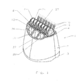
- a hair treatment device 1 shown in the accompanying figures is of the type intended to be attached to the blower end of a hair dryer.
- a hair dryer (not shown in the figures) generally comprises a tubular housing enclosing a fan which produces a flow of air between an air inlet end and a blown air outlet end, electric heating element arranged in the housing upstream of the air outlet orifice.
- the housing is extended downwards by a gripping handle enclosing the electrical control and connection part of the appliance to the power supply, the handle being furthermore provided with control and selection buttons for the operating mode (in particular adjustment of the supply air flow, the temperature) of the hair dryer.
- the hair treatment device 1 comprises a hollow housing 2, open at the ends, having a slightly flared shape from an air outlet end 4 to an end of air inlet 3.
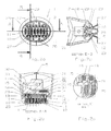
- the housing 2 comprises, at the air inlet end 3, means for attachment to the air outlet orifice of the hair dryer. These means may be, for example, grooves 5 ( Fig. 2b and Fig. 3b ) in which elastic fastening hooks belonging to the housing of the hair dryer are inserted.
- the device includes hair treatment elements in the form of clamping blades 7 arranged side by side and forming a row 8 disposed at the air outlet end 4 of the device, in particular diametrically or centered according to the largest longitudinal dimension of the opening of this end part.
- the row 8 of clamping blades 7 is formed of several pairs of blades side by side, each pair comprising a movable blade 10 and a fixed blade 11.
- the fixed blades 11 are integral with a housing 12 mounted fixed inside of the housing 2 of the device.
- the fixed blades 11 are advantageously made in one piece, by a plastic molding technique, with the housing 12.
- the fixed blades 11 have a trapezoidal shape, the base being fixed to the housing 12 and the front end being protruding relative to the latter and relative to the housing 2 of the device.
- the profile of the fixed blades 11 is rounded and slightly flared towards the base to allow better penetration into the hair of their front end.
- Air outlet openings 28 are provided between the inner walls of the housing 2 of the device and those of the housing 12, on either side of the row 8 of clamping blades 7.
- the movable blades 10 are carried by a walker 14. According to the invention, each movable blade 10 is mounted under the pressure of a compression spring 15, with possibility of movement in a specific housing 16 within the player 14.
- the player 14 is a generally L-shaped piece whose longest side forms the base 18 of the player and the shorter side forms a transverse arm 17 connected to an actuating system, as will be explained later.
- the base 18 of the player 14 comprises several vertical walls 19, neighboring walls delimiting, along the length of the base 18, housings 16 for receiving the movable blades 10.
- a housing 16 is thus provided to receive a movable blade 10 and its spring 15 (only two springs 15 have been shown in FIGS. figures 2b and 3b , but it is easy to understand that each housing 16 includes one).
- the shape of the base 18 of the player 14 and that of a vertical wall 19 are better visible at the Figure 2c where we also note the shape of the upper portion 20 of a movable blade 10 which is protruding relative to a vertical wall 19
- a movable blade 10 has a cross section ( fig.2b, 2d and 3B , 3d) of doubly bent shape, with the lower portion 21 slidably mounted within the player 14. More particularly, the lower portion 21 of the movable blade 10 is traversed by two parallel guide rods 23, carried by the vertical walls 19 of the Walkman 14. A movable blade 10 is thus caused to slide horizontally, under the pressure of a compression spring 15 inside a housing 16.
- the upper part 20 of a movable blade 10 has a rectangular shape with a rounded front end.
- the profile of a movable blade 10 is generally flat, of almost constant thickness over its height.
- a movable blade is advantageously made of a thermally conductive material, for example coated aluminum, at least in its upper part for contact with the hair to be treated, a ceramic material or a fine glass deposit.
- the movable blade may be made of a plastic material, possibly covered at its upper part, with a metal or thermally conductive deposit.
- the player 14 carrying the movable blades 10 is driven in motion by an actuating system 30.
- the actuating system 30 comprises an electromagnet 31 comprising a horizontal rod 32 fixed with the aid of a rivet 33 at the end of the arm 17 of the player 14.
- the electromagnet 31 is of the single-acting type
- the return to the rest position of the player 14 is done using a return spring 35.
- the return spring 35 is mounted between an abutment 36 of the mobile player 14 and the inner wall of a frame 37 fixedly mounted relative to the casing 12.
- the casing 12 can be fixed at its lower part by screws attachment to the frame 37 with which it forms a protective envelope of the blades of clamping and their actuating mechanism.
- FIGS. 1 to 2c represent the device of the invention with the clamping blades 7 in the open or rest position.
- two adjacent blades forming a clamp including a movable blade 10 and a fixed blade 11 define an interval 25 for introduction of the hair to be treated.
- a row 8 thus has several intervals 25 uniformly distributed along its length.
- the device also comprises pins 27 arranged on either side of the row 8. In the embodiment shown in the drawings, the pins are arranged in zigzag by group three of the width of a gap 25, which allows better seizure of the hair to channel them in the gap 25 for the purpose of treatment.
- the movable blades 10 have a width less than that of the fixed blades 11 and are made to be housed inside the latter in the rest position illustrated in FIGS. Figures 1 to 2c , which allows the hair to slide better between the open blades to easily enter the intervals 25.
- the device In operation, the device is attached to the outlet end of a hair dryer and is introduced into the hair.
- the fixed blades 11 can then penetrate to the scalp and support it.
- the closing of the clamping blades 7 can be controlled by a command sent to the electromagnet 31.
- the electromagnet 31 then attracts the rod 32 inwards, against the force of the return spring 35, which has the effect of moving the sliding device 14 with the movable blades 10 in the position shown in FIGS. Figures 3a and 3b .
- the movable blades 10 initially pressed by the force of the return spring 35 on fixed blades 11 on the left, move against the fixed blades 11 adjacent to the right.
- each movable blade 10 can move individually, against its own compression spring 15 depending on the thickness of the lock of hair that it presses against an adjacent fixed blade 11. This allows the set of clamping blades to apply a balanced force and thus a uniform treatment on each of the locks, this not being influenced by the thickness or the length of the lock, all the locks being thus correctly treated.
- the rest of the hair mass is then treated in the same way, starting from the base of the scalp and to the tip of the hair, which makes it possible to evenly treat even very short hair, these being seized as soon as possible. the closing of the clamping blades.
- the electromagnet 31 is connected to electrical supply and control means specific to the processing device 1, its actuation being triggered by the user by means of a control button located for example on the housing 2 of the device.
- the electromagnet 31 is connected to the electrical power supply and control means of the hair dryer, the device then comprising an electrical connector cooperating with a complementary connector belonging to the housing of the hair dryer.
- the control of the electromagnet could be done remotely from the handle of the hair dryer.
- FIGS. 4 and 5 illustrate a treatment device 1 according to a second embodiment of the invention in which it is noted: a casing 2 forming a protective fairing of a row 8 of nine pairs of clamping blades, each pair being formed of a blade fixed 10 and a movable blade 11 adjacent vis-à-vis.
- the movable blades 11 are supported by a walkman 14 itself mobile.
- each movable blade 11 is pivotally mounted, under the thrust of a compression spring 15, about an axis 40 integral with the player 14.
- a cover 41 is integral with the housing 2 and carries a pivot axis 42 a lever 43 for transmitting the movement of actuation of the player 14 from an actuating system external to the device, as will be explained later.
- the sliding movement of the player 14 is carried out in the direction of its length (perpendicular to the blades) and is received by the player 14 at its stop 44 by means of a return arm 45 of the lever 43 bent, the other actuating arm 46 of the lever 43 receiving the actuating movement according to the arrow F on the figure 2 .
- the movement according to the arrow F is advantageously received from an electromagnet (not shown in the drawings) disposed in the housing of the apparatus, in particular a hair dryer.
- the electromagnet in the housing thereof.
- the electromagnet then exerts a push along the arrow F of the figure 4 parallel to the longitudinal axis of the hair dryer housing (or parallel to the airflow blown by the hair dryer).
- the movement of the electromagnet in the direction F is converted by a lever 43 into a movement perpendicular to the direction F, or perpendicular to the direction of the air flow, corresponding to the direction of movement of the player 14.
- the movement of the player 14 is carried out under the thrust of a return spring 35 allowing the return of the player in the initial position when the electromagnet is no longer supplied.
- the electromagnet is dimensioned so as to exert a force greater than that of the compression spring 35, added to that of the nine compression springs 15 of the movable blades 11, while taking into account the reduction ratio of the lever 43.
- the fixed blades 10 are themselves held by a support 48 mounted fixed relative to the housing 2. Fixing screws 49 hold all of these components integral with the housing 2.
- the housing 2 has a fixing end 50 to the air outlet of the housing of a hair dryer, the opposite end having arches 51 for protecting the fixed blades 10.
- Two rows of pins 27 are disposed on either side of the arches, parallel to the row of blades. and are intended to grasp and align the hair before insertion between the blades of the treatment device 1.
- Air outlet orifices are made on the front of the housing 2, on both sides of the arches 51.
- the electromagnet thrust in the direction F the lever 43 converts this longitudinal movement (along the axis of the hair dryer housing) into a transverse movement of the player 14, compressing the spring 35.
- the springs of compression 15 of the movable blades 11 are also compressed by the force exerted on the blades by the hair introduced between the blades at the time of closure of the gap 25.
- the treatment device comprises means 7 for detecting the presence of the hair between the fixed blades 10 and mobile 11 of the device.
- the detection means comprise a transmitter and an infrared beam receiver disposed in the housing of the hair dryer, the infrared beam arriving at the processing device 1 via an optical guide 52.
- the IR beam from the transmitter of the housing arrives parallel to the blades of the device and is returned in a direction perpendicular to the blades by a transmitter prism 53 having a return angle of 45 °.
- the beam passes through a series of orifices 54 of oblong shape made throughout the series of blades, fixed and movable.
- the incident beam After passing through the series of blades, the incident beam encounters a plane mirror 55 arranged parallel to the blades and is returned by this mirror again towards the orifices 54 of the fixed and movable blades which it crosses before reaching the level of the guide optical 52 which leads to the IR receiver of the housing.
- the hair taking place in the intervals 25 they cut the beam of IR radius and IR receiver no longer detects emission, it actuates the electromagnet 35.
- the movable blades 10 are in the rest position within an interval 25, for example in a central position, their displacement can then be made on the right and / or left relative to this rest position to smooth the hair inserted on both sides of the movable blades.
- all the clamping blades of the row are movable, being carried by two different players controlled in opposite directions to approach and respectively separate two blades of a pair to open and close the gap between two adjacent blades.
- the actuating system may be a wax cylinder moved by heat, for example that from a hair dryer.
- the actuation system may comprise a compressed air cartridge for rapid action on the player.
- the treatment device may also be provided with a handle and may include its own power supply means, its own heating means and operation control.
Landscapes
- Cleaning And Drying Hair (AREA)
- Brushes (AREA)
- Massaging Devices (AREA)
Applications Claiming Priority (2)
| Application Number | Priority Date | Filing Date | Title |
|---|---|---|---|
| FR0507140A FR2888095B1 (fr) | 2005-07-05 | 2005-07-05 | Dispositif de traitement des cheveux et appareil de traitement des cheveux comportant un tel dispositif |
| EP06778783A EP1898740B1 (de) | 2005-07-05 | 2006-07-05 | Haarbehandlungsvorrichtung und damit versehenes haarbehandlungsgerät |
Related Parent Applications (1)
| Application Number | Title | Priority Date | Filing Date |
|---|---|---|---|
| EP06778783.8 Division | 2006-07-05 |
Publications (2)
| Publication Number | Publication Date |
|---|---|
| EP2258232A1 true EP2258232A1 (de) | 2010-12-08 |
| EP2258232B1 EP2258232B1 (de) | 2013-08-07 |
Family
ID=36125963
Family Applications (3)
| Application Number | Title | Priority Date | Filing Date |
|---|---|---|---|
| EP10172525.7A Expired - Lifetime EP2258232B1 (de) | 2005-07-05 | 2006-07-05 | Vorrichtung zur Haarbehandlung und Haarbehandlungsgerät, das eine solche Vorrichtung umfasst |
| EP06778783A Expired - Lifetime EP1898740B1 (de) | 2005-07-05 | 2006-07-05 | Haarbehandlungsvorrichtung und damit versehenes haarbehandlungsgerät |
| EP06778784A Withdrawn EP1898741A1 (de) | 2005-07-05 | 2006-07-05 | Verbesserte frisiervorrichtung |
Family Applications After (2)
| Application Number | Title | Priority Date | Filing Date |
|---|---|---|---|
| EP06778783A Expired - Lifetime EP1898740B1 (de) | 2005-07-05 | 2006-07-05 | Haarbehandlungsvorrichtung und damit versehenes haarbehandlungsgerät |
| EP06778784A Withdrawn EP1898741A1 (de) | 2005-07-05 | 2006-07-05 | Verbesserte frisiervorrichtung |
Country Status (8)
| Country | Link |
|---|---|
| EP (3) | EP2258232B1 (de) |
| CN (2) | CN101822457B (de) |
| AT (1) | ATE508657T1 (de) |
| BR (1) | BRPI0614203A2 (de) |
| ES (1) | ES2364346T3 (de) |
| FR (1) | FR2888095B1 (de) |
| RU (1) | RU2407414C2 (de) |
| WO (2) | WO2007003795A2 (de) |
Families Citing this family (21)
| Publication number | Priority date | Publication date | Assignee | Title |
|---|---|---|---|---|
| FR2916945B1 (fr) * | 2007-06-05 | 2009-07-17 | Seb Sa | Appareil de traitement des cheveux |
| FR2916946B1 (fr) * | 2007-06-05 | 2009-07-17 | Seb Sa | Appareil de lissage des cheveux |
| FR2916947B1 (fr) * | 2007-06-05 | 2009-08-14 | Seb Sa | Appareil de lissage des cheveux |
| US8800163B2 (en) * | 2007-08-21 | 2014-08-12 | Heidi Schmid | Hair care appliance and method of using same |
| DE102008028566A1 (de) * | 2008-06-16 | 2009-12-17 | BSH Bosch und Siemens Hausgeräte GmbH | Vorrichtung zum Glätten vo Haaren |
| FR2933852B1 (fr) | 2008-07-21 | 2011-03-25 | Seb Sa | Dispositif de lissage des cheveux integrant des moyens de chauffage |
| US8424543B2 (en) | 2010-06-30 | 2013-04-23 | Elc Management Llc | Red light emitting device for use with hair product and blow dryer |
| FR2968511B1 (fr) | 2010-12-08 | 2013-10-18 | Seb Sa | Accessoire de mise en forme de cheveux |
| DE202011050030U1 (de) * | 2011-05-04 | 2012-08-06 | Wik Far East Ltd. | Haarformvorrichtung |
| DE202011050034U1 (de) * | 2011-05-04 | 2012-08-06 | Wik Far East Ltd. | Haarformvorrichtung |
| FR2980084B1 (fr) | 2011-09-19 | 2015-04-24 | Seb Sa | Accessoire de coiffure pour seche-cheveux |
| US8881423B2 (en) | 2012-08-24 | 2014-11-11 | M. M. & R. Products, Inc. | Concentrator |
| FR3045286B1 (fr) * | 2015-12-18 | 2018-02-02 | L'oreal | Recharge de produit cosmetique pour dispositif de traitement de la chevelure a element chauffant et dispositif de traitement de la chevelure incluant une telle recharge |
| US11363871B2 (en) * | 2016-09-19 | 2022-06-21 | Diversame, Inc. | Hair styling device |
| FR3076189B1 (fr) * | 2017-12-29 | 2021-09-10 | Seb Sa | Appareil de coiffage a cinematique amelioree |
| EP3530139B1 (de) * | 2018-02-23 | 2020-10-07 | Kan Holding AS | Frisiervorrichtung |
| USD959053S1 (en) | 2018-03-09 | 2022-07-26 | M. M. & R. Products, Inc. | Hair styling apparatus |
| USD900391S1 (en) | 2018-03-09 | 2020-10-27 | M.M. & R. Products, Inc. | Hair styling apparatus |
| GB2630758A (en) * | 2023-06-06 | 2024-12-11 | Dyson Technology Ltd | Comb assembly and haircare appliance |
| WO2025049171A1 (en) * | 2023-08-25 | 2025-03-06 | Sharkninja Operating Llc | Heated hair comb attachment |
| GB2637020A (en) * | 2024-01-04 | 2025-07-09 | Dyson Technology Ltd | A hair care apparatus |
Citations (4)
| Publication number | Priority date | Publication date | Assignee | Title |
|---|---|---|---|---|
| US1002942A (en) * | 1910-08-29 | 1911-09-12 | Edward Hiram Taylor | Hair-ironing comb. |
| US5553632A (en) | 1995-03-03 | 1996-09-10 | Burkhardt; Charles W. | Hair styling device |
| EP1124466A1 (de) | 1998-10-30 | 2001-08-22 | Seb S.A. | Zubehör zum glätten von haaren |
| WO2004066779A1 (en) * | 2003-01-30 | 2004-08-12 | Dickson Industrial Co. Ltd. | Hair styling attachment |
Family Cites Families (5)
| Publication number | Priority date | Publication date | Assignee | Title |
|---|---|---|---|---|
| US1002715A (en) * | 1911-04-29 | 1911-09-05 | Frank J Lilak | Auger-gage. |
| DE4117708A1 (de) * | 1990-06-07 | 1991-12-12 | Wella Ag | Behandlungsgeraet in offener bauweise fuer menschliche kopfhaare |
| CN2111023U (zh) * | 1992-01-08 | 1992-07-29 | 吴盛兴 | 吹风梳子 |
| DE4306429A1 (de) * | 1993-03-02 | 1994-09-29 | Wella Ag | Verfahren zum Behandeln eines Objekts mit einem Warmluftstrom und Handgerät zur Durchführung des Verfahrens |
| CN2568033Y (zh) * | 2002-09-06 | 2003-08-27 | 何小波 | 一种多功能电吹按摩器 |
-
2005
- 2005-07-05 FR FR0507140A patent/FR2888095B1/fr not_active Expired - Fee Related
-
2006
- 2006-07-05 EP EP10172525.7A patent/EP2258232B1/de not_active Expired - Lifetime
- 2006-07-05 EP EP06778783A patent/EP1898740B1/de not_active Expired - Lifetime
- 2006-07-05 EP EP06778784A patent/EP1898741A1/de not_active Withdrawn
- 2006-07-05 AT AT06778783T patent/ATE508657T1/de not_active IP Right Cessation
- 2006-07-05 ES ES06778783T patent/ES2364346T3/es not_active Expired - Lifetime
- 2006-07-05 RU RU2008104267/12A patent/RU2407414C2/ru not_active IP Right Cessation
- 2006-07-05 WO PCT/FR2006/001603 patent/WO2007003795A2/fr not_active Ceased
- 2006-07-05 WO PCT/FR2006/001604 patent/WO2007003796A1/fr not_active Ceased
- 2006-07-05 CN CN2010101167649A patent/CN101822457B/zh not_active Expired - Fee Related
- 2006-07-05 CN CN2006800244461A patent/CN101212915B/zh not_active Expired - Fee Related
- 2006-07-05 BR BRPI0614203-6A patent/BRPI0614203A2/pt not_active IP Right Cessation
Patent Citations (4)
| Publication number | Priority date | Publication date | Assignee | Title |
|---|---|---|---|---|
| US1002942A (en) * | 1910-08-29 | 1911-09-12 | Edward Hiram Taylor | Hair-ironing comb. |
| US5553632A (en) | 1995-03-03 | 1996-09-10 | Burkhardt; Charles W. | Hair styling device |
| EP1124466A1 (de) | 1998-10-30 | 2001-08-22 | Seb S.A. | Zubehör zum glätten von haaren |
| WO2004066779A1 (en) * | 2003-01-30 | 2004-08-12 | Dickson Industrial Co. Ltd. | Hair styling attachment |
Also Published As
| Publication number | Publication date |
|---|---|
| ES2364346T3 (es) | 2011-08-31 |
| CN101822457A (zh) | 2010-09-08 |
| CN101822457B (zh) | 2012-05-23 |
| WO2007003795A3 (fr) | 2007-02-22 |
| ATE508657T1 (de) | 2011-05-15 |
| EP2258232B1 (de) | 2013-08-07 |
| WO2007003795A2 (fr) | 2007-01-11 |
| FR2888095B1 (fr) | 2007-09-07 |
| EP1898741A1 (de) | 2008-03-19 |
| BRPI0614203A2 (pt) | 2011-04-05 |
| CN101212915A (zh) | 2008-07-02 |
| RU2008104267A (ru) | 2009-08-10 |
| FR2888095A1 (fr) | 2007-01-12 |
| WO2007003796A1 (fr) | 2007-01-11 |
| RU2407414C2 (ru) | 2010-12-27 |
| EP1898740A2 (de) | 2008-03-19 |
| EP1898740B1 (de) | 2011-05-11 |
| CN101212915B (zh) | 2010-05-19 |
Similar Documents
| Publication | Publication Date | Title |
|---|---|---|
| EP2258232B1 (de) | Vorrichtung zur Haarbehandlung und Haarbehandlungsgerät, das eine solche Vorrichtung umfasst | |
| EP2378915B1 (de) | Frisiergerät | |
| EP2312967B1 (de) | Haarglättungsvorrichtung mit einem eingebauten heizmittel | |
| EP2120629B1 (de) | Frisiervorrichtung | |
| FR2913317A1 (fr) | Appareil de coiffure | |
| EP2152117B1 (de) | Haarbehandlungsvorrichtung | |
| WO2008129172A2 (fr) | Appareil de coiffure | |
| EP2145557A1 (de) | Frisierapparat mit konstantem Druck | |
| EP3100633B1 (de) | Elektrisches haarpflegegerät | |
| WO1995017122A1 (fr) | Grille-pain electrique comportant un chariot de commande a double detente | |
| EP2152116B1 (de) | Haarglättungsvorrichtung | |
| EP2152115A2 (de) | Haarkräftigungsmittel | |
| EP3240453B1 (de) | Multifunktionshaarfrisiervorrichtung in form einer drehbürste | |
| WO2019129874A1 (fr) | Appareil de coiffage automatique | |
| FR2713907A1 (fr) | Grille-pain électrique à double chariot porte-pain. |
Legal Events
| Date | Code | Title | Description |
|---|---|---|---|
| PUAI | Public reference made under article 153(3) epc to a published international application that has entered the european phase |
Free format text: ORIGINAL CODE: 0009012 |
|
| AC | Divisional application: reference to earlier application |
Ref document number: 1898740 Country of ref document: EP Kind code of ref document: P |
|
| AK | Designated contracting states |
Kind code of ref document: A1 Designated state(s): AT BE BG CH CY CZ DE DK EE ES FI FR GB GR HU IE IS IT LI LT LU LV MC NL PL PT RO SE SI SK TR |
|
| AX | Request for extension of the european patent |
Extension state: AL BA HR MK RS |
|
| 17P | Request for examination filed |
Effective date: 20110525 |
|
| GRAP | Despatch of communication of intention to grant a patent |
Free format text: ORIGINAL CODE: EPIDOSNIGR1 |
|
| GRAS | Grant fee paid |
Free format text: ORIGINAL CODE: EPIDOSNIGR3 |
|
| GRAA | (expected) grant |
Free format text: ORIGINAL CODE: 0009210 |
|
| AC | Divisional application: reference to earlier application |
Ref document number: 1898740 Country of ref document: EP Kind code of ref document: P |
|
| AK | Designated contracting states |
Kind code of ref document: B1 Designated state(s): AT BE BG CH CY CZ DE DK EE ES FI FR GB GR HU IE IS IT LI LT LU LV MC NL PL PT RO SE SI SK TR |
|
| REG | Reference to a national code |
Ref country code: GB Ref legal event code: FG4D Free format text: NOT ENGLISH |
|
| REG | Reference to a national code |
Ref country code: AT Ref legal event code: REF Ref document number: 625319 Country of ref document: AT Kind code of ref document: T Effective date: 20130815 Ref country code: CH Ref legal event code: EP |
|
| REG | Reference to a national code |
Ref country code: IE Ref legal event code: FG4D Free format text: LANGUAGE OF EP DOCUMENT: FRENCH |
|
| REG | Reference to a national code |
Ref country code: DE Ref legal event code: R096 Ref document number: 602006037782 Country of ref document: DE Effective date: 20131002 |
|
| REG | Reference to a national code |
Ref country code: AT Ref legal event code: MK05 Ref document number: 625319 Country of ref document: AT Kind code of ref document: T Effective date: 20130807 |
|
| REG | Reference to a national code |
Ref country code: NL Ref legal event code: VDEP Effective date: 20130807 |
|
| REG | Reference to a national code |
Ref country code: LT Ref legal event code: MG4D |
|
| PG25 | Lapsed in a contracting state [announced via postgrant information from national office to epo] |
Ref country code: AT Free format text: LAPSE BECAUSE OF FAILURE TO SUBMIT A TRANSLATION OF THE DESCRIPTION OR TO PAY THE FEE WITHIN THE PRESCRIBED TIME-LIMIT Effective date: 20130807 Ref country code: LT Free format text: LAPSE BECAUSE OF FAILURE TO SUBMIT A TRANSLATION OF THE DESCRIPTION OR TO PAY THE FEE WITHIN THE PRESCRIBED TIME-LIMIT Effective date: 20130807 Ref country code: SE Free format text: LAPSE BECAUSE OF FAILURE TO SUBMIT A TRANSLATION OF THE DESCRIPTION OR TO PAY THE FEE WITHIN THE PRESCRIBED TIME-LIMIT Effective date: 20130807 Ref country code: IS Free format text: LAPSE BECAUSE OF FAILURE TO SUBMIT A TRANSLATION OF THE DESCRIPTION OR TO PAY THE FEE WITHIN THE PRESCRIBED TIME-LIMIT Effective date: 20131207 Ref country code: CY Free format text: LAPSE BECAUSE OF FAILURE TO SUBMIT A TRANSLATION OF THE DESCRIPTION OR TO PAY THE FEE WITHIN THE PRESCRIBED TIME-LIMIT Effective date: 20130911 Ref country code: PT Free format text: LAPSE BECAUSE OF FAILURE TO SUBMIT A TRANSLATION OF THE DESCRIPTION OR TO PAY THE FEE WITHIN THE PRESCRIBED TIME-LIMIT Effective date: 20131209 |
|
| PG25 | Lapsed in a contracting state [announced via postgrant information from national office to epo] |
Ref country code: NL Free format text: LAPSE BECAUSE OF FAILURE TO SUBMIT A TRANSLATION OF THE DESCRIPTION OR TO PAY THE FEE WITHIN THE PRESCRIBED TIME-LIMIT Effective date: 20130807 Ref country code: GR Free format text: LAPSE BECAUSE OF FAILURE TO SUBMIT A TRANSLATION OF THE DESCRIPTION OR TO PAY THE FEE WITHIN THE PRESCRIBED TIME-LIMIT Effective date: 20131108 Ref country code: FI Free format text: LAPSE BECAUSE OF FAILURE TO SUBMIT A TRANSLATION OF THE DESCRIPTION OR TO PAY THE FEE WITHIN THE PRESCRIBED TIME-LIMIT Effective date: 20130807 Ref country code: PL Free format text: LAPSE BECAUSE OF FAILURE TO SUBMIT A TRANSLATION OF THE DESCRIPTION OR TO PAY THE FEE WITHIN THE PRESCRIBED TIME-LIMIT Effective date: 20130807 Ref country code: LV Free format text: LAPSE BECAUSE OF FAILURE TO SUBMIT A TRANSLATION OF THE DESCRIPTION OR TO PAY THE FEE WITHIN THE PRESCRIBED TIME-LIMIT Effective date: 20130807 Ref country code: SI Free format text: LAPSE BECAUSE OF FAILURE TO SUBMIT A TRANSLATION OF THE DESCRIPTION OR TO PAY THE FEE WITHIN THE PRESCRIBED TIME-LIMIT Effective date: 20130807 |
|
| PG25 | Lapsed in a contracting state [announced via postgrant information from national office to epo] |
Ref country code: CY Free format text: LAPSE BECAUSE OF FAILURE TO SUBMIT A TRANSLATION OF THE DESCRIPTION OR TO PAY THE FEE WITHIN THE PRESCRIBED TIME-LIMIT Effective date: 20130807 |
|
| PG25 | Lapsed in a contracting state [announced via postgrant information from national office to epo] |
Ref country code: DK Free format text: LAPSE BECAUSE OF FAILURE TO SUBMIT A TRANSLATION OF THE DESCRIPTION OR TO PAY THE FEE WITHIN THE PRESCRIBED TIME-LIMIT Effective date: 20130807 Ref country code: RO Free format text: LAPSE BECAUSE OF FAILURE TO SUBMIT A TRANSLATION OF THE DESCRIPTION OR TO PAY THE FEE WITHIN THE PRESCRIBED TIME-LIMIT Effective date: 20130807 Ref country code: SK Free format text: LAPSE BECAUSE OF FAILURE TO SUBMIT A TRANSLATION OF THE DESCRIPTION OR TO PAY THE FEE WITHIN THE PRESCRIBED TIME-LIMIT Effective date: 20130807 Ref country code: EE Free format text: LAPSE BECAUSE OF FAILURE TO SUBMIT A TRANSLATION OF THE DESCRIPTION OR TO PAY THE FEE WITHIN THE PRESCRIBED TIME-LIMIT Effective date: 20130807 Ref country code: CZ Free format text: LAPSE BECAUSE OF FAILURE TO SUBMIT A TRANSLATION OF THE DESCRIPTION OR TO PAY THE FEE WITHIN THE PRESCRIBED TIME-LIMIT Effective date: 20130807 |
|
| PG25 | Lapsed in a contracting state [announced via postgrant information from national office to epo] |
Ref country code: IT Free format text: LAPSE BECAUSE OF FAILURE TO SUBMIT A TRANSLATION OF THE DESCRIPTION OR TO PAY THE FEE WITHIN THE PRESCRIBED TIME-LIMIT Effective date: 20130807 Ref country code: ES Free format text: LAPSE BECAUSE OF FAILURE TO SUBMIT A TRANSLATION OF THE DESCRIPTION OR TO PAY THE FEE WITHIN THE PRESCRIBED TIME-LIMIT Effective date: 20130807 |
|
| PLBE | No opposition filed within time limit |
Free format text: ORIGINAL CODE: 0009261 |
|
| STAA | Information on the status of an ep patent application or granted ep patent |
Free format text: STATUS: NO OPPOSITION FILED WITHIN TIME LIMIT |
|
| 26N | No opposition filed |
Effective date: 20140508 |
|
| REG | Reference to a national code |
Ref country code: DE Ref legal event code: R097 Ref document number: 602006037782 Country of ref document: DE Effective date: 20140508 |
|
| REG | Reference to a national code |
Ref country code: DE Ref legal event code: R119 Ref document number: 602006037782 Country of ref document: DE |
|
| PG25 | Lapsed in a contracting state [announced via postgrant information from national office to epo] |
Ref country code: LU Free format text: LAPSE BECAUSE OF FAILURE TO SUBMIT A TRANSLATION OF THE DESCRIPTION OR TO PAY THE FEE WITHIN THE PRESCRIBED TIME-LIMIT Effective date: 20140705 |
|
| REG | Reference to a national code |
Ref country code: CH Ref legal event code: PL |
|
| GBPC | Gb: european patent ceased through non-payment of renewal fee |
Effective date: 20140705 |
|
| REG | Reference to a national code |
Ref country code: IE Ref legal event code: MM4A |
|
| PG25 | Lapsed in a contracting state [announced via postgrant information from national office to epo] |
Ref country code: LI Free format text: LAPSE BECAUSE OF NON-PAYMENT OF DUE FEES Effective date: 20140731 Ref country code: DE Free format text: LAPSE BECAUSE OF NON-PAYMENT OF DUE FEES Effective date: 20150203 Ref country code: CH Free format text: LAPSE BECAUSE OF NON-PAYMENT OF DUE FEES Effective date: 20140731 |
|
| REG | Reference to a national code |
Ref country code: DE Ref legal event code: R119 Ref document number: 602006037782 Country of ref document: DE Effective date: 20150203 |
|
| PG25 | Lapsed in a contracting state [announced via postgrant information from national office to epo] |
Ref country code: GB Free format text: LAPSE BECAUSE OF NON-PAYMENT OF DUE FEES Effective date: 20140705 |
|
| PG25 | Lapsed in a contracting state [announced via postgrant information from national office to epo] |
Ref country code: IE Free format text: LAPSE BECAUSE OF NON-PAYMENT OF DUE FEES Effective date: 20140705 |
|
| PG25 | Lapsed in a contracting state [announced via postgrant information from national office to epo] |
Ref country code: MC Free format text: LAPSE BECAUSE OF FAILURE TO SUBMIT A TRANSLATION OF THE DESCRIPTION OR TO PAY THE FEE WITHIN THE PRESCRIBED TIME-LIMIT Effective date: 20130807 |
|
| PG25 | Lapsed in a contracting state [announced via postgrant information from national office to epo] |
Ref country code: BG Free format text: LAPSE BECAUSE OF FAILURE TO SUBMIT A TRANSLATION OF THE DESCRIPTION OR TO PAY THE FEE WITHIN THE PRESCRIBED TIME-LIMIT Effective date: 20130807 |
|
| PG25 | Lapsed in a contracting state [announced via postgrant information from national office to epo] |
Ref country code: HU Free format text: LAPSE BECAUSE OF FAILURE TO SUBMIT A TRANSLATION OF THE DESCRIPTION OR TO PAY THE FEE WITHIN THE PRESCRIBED TIME-LIMIT; INVALID AB INITIO Effective date: 20060705 Ref country code: BE Free format text: LAPSE BECAUSE OF FAILURE TO SUBMIT A TRANSLATION OF THE DESCRIPTION OR TO PAY THE FEE WITHIN THE PRESCRIBED TIME-LIMIT Effective date: 20140731 Ref country code: TR Free format text: LAPSE BECAUSE OF FAILURE TO SUBMIT A TRANSLATION OF THE DESCRIPTION OR TO PAY THE FEE WITHIN THE PRESCRIBED TIME-LIMIT Effective date: 20130807 |
|
| REG | Reference to a national code |
Ref country code: FR Ref legal event code: PLFP Year of fee payment: 11 |
|
| REG | Reference to a national code |
Ref country code: FR Ref legal event code: CA Effective date: 20170518 |
|
| REG | Reference to a national code |
Ref country code: FR Ref legal event code: PLFP Year of fee payment: 12 |
|
| REG | Reference to a national code |
Ref country code: FR Ref legal event code: PLFP Year of fee payment: 13 |
|
| P01 | Opt-out of the competence of the unified patent court (upc) registered |
Effective date: 20230517 |
|
| PGFP | Annual fee paid to national office [announced via postgrant information from national office to epo] |
Ref country code: FR Payment date: 20230727 Year of fee payment: 18 |
|
| PG25 | Lapsed in a contracting state [announced via postgrant information from national office to epo] |
Ref country code: FR Free format text: LAPSE BECAUSE OF NON-PAYMENT OF DUE FEES Effective date: 20240731 |