EP2258461A1 - CO2-Rückgewinnungsvorrichtung - Google Patents
CO2-Rückgewinnungsvorrichtung Download PDFInfo
- Publication number
- EP2258461A1 EP2258461A1 EP09174655A EP09174655A EP2258461A1 EP 2258461 A1 EP2258461 A1 EP 2258461A1 EP 09174655 A EP09174655 A EP 09174655A EP 09174655 A EP09174655 A EP 09174655A EP 2258461 A1 EP2258461 A1 EP 2258461A1
- Authority
- EP
- European Patent Office
- Prior art keywords
- absorbing liquid
- absorber
- flue gas
- regenerator
- recovering apparatus
- Prior art date
- Legal status (The legal status is an assumption and is not a legal conclusion. Google has not performed a legal analysis and makes no representation as to the accuracy of the status listed.)
- Granted
Links
- 239000007788 liquid Substances 0.000 claims abstract description 73
- 239000002904 solvent Substances 0.000 claims abstract description 35
- UGFAIRIUMAVXCW-UHFFFAOYSA-N Carbon monoxide Chemical compound [O+]#[C-] UGFAIRIUMAVXCW-UHFFFAOYSA-N 0.000 claims abstract description 34
- 239000003546 flue gas Substances 0.000 claims abstract description 34
- 239000006096 absorbing agent Substances 0.000 claims abstract description 32
- 239000002184 metal Substances 0.000 claims description 3
- 239000012765 fibrous filler Substances 0.000 claims description 2
- 239000002657 fibrous material Substances 0.000 claims description 2
- QVGXLLKOCUKJST-UHFFFAOYSA-N atomic oxygen Chemical compound [O] QVGXLLKOCUKJST-UHFFFAOYSA-N 0.000 description 21
- 229910052760 oxygen Inorganic materials 0.000 description 21
- 239000001301 oxygen Substances 0.000 description 21
- 239000007789 gas Substances 0.000 description 15
- XLYOFNOQVPJJNP-UHFFFAOYSA-N water Substances O XLYOFNOQVPJJNP-UHFFFAOYSA-N 0.000 description 6
- 238000000034 method Methods 0.000 description 5
- 150000001412 amines Chemical class 0.000 description 3
- 238000010792 warming Methods 0.000 description 3
- NINIDFKCEFEMDL-UHFFFAOYSA-N Sulfur Chemical compound [S] NINIDFKCEFEMDL-UHFFFAOYSA-N 0.000 description 2
- 239000003054 catalyst Substances 0.000 description 2
- 238000006243 chemical reaction Methods 0.000 description 2
- 238000002485 combustion reaction Methods 0.000 description 2
- 239000000498 cooling water Substances 0.000 description 2
- 230000000694 effects Effects 0.000 description 2
- 239000002803 fossil fuel Substances 0.000 description 2
- 239000003595 mist Substances 0.000 description 2
- 238000000926 separation method Methods 0.000 description 2
- 239000000126 substance Substances 0.000 description 2
- 229910052717 sulfur Inorganic materials 0.000 description 2
- 239000011593 sulfur Substances 0.000 description 2
- 238000005406 washing Methods 0.000 description 2
- IJGRMHOSHXDMSA-UHFFFAOYSA-N Atomic nitrogen Chemical compound N#N IJGRMHOSHXDMSA-UHFFFAOYSA-N 0.000 description 1
- 239000000470 constituent Substances 0.000 description 1
- 230000007797 corrosion Effects 0.000 description 1
- 238000005260 corrosion Methods 0.000 description 1
- 230000006866 deterioration Effects 0.000 description 1
- 238000010586 diagram Methods 0.000 description 1
- 238000005516 engineering process Methods 0.000 description 1
- 239000000835 fiber Substances 0.000 description 1
- 239000000945 filler Substances 0.000 description 1
- 239000000463 material Substances 0.000 description 1
- 238000011084 recovery Methods 0.000 description 1
- 230000001172 regenerating effect Effects 0.000 description 1
- 239000007787 solid Substances 0.000 description 1
Images

Classifications
-
- B—PERFORMING OPERATIONS; TRANSPORTING
- B01—PHYSICAL OR CHEMICAL PROCESSES OR APPARATUS IN GENERAL
- B01D—SEPARATION
- B01D53/00—Separation of gases or vapours; Recovering vapours of volatile solvents from gases; Chemical or biological purification of waste gases, e.g. engine exhaust gases, smoke, fumes, flue gases, aerosols
- B01D53/14—Separation of gases or vapours; Recovering vapours of volatile solvents from gases; Chemical or biological purification of waste gases, e.g. engine exhaust gases, smoke, fumes, flue gases, aerosols by absorption
- B01D53/1456—Removing acid components
- B01D53/1475—Removing carbon dioxide
-
- B—PERFORMING OPERATIONS; TRANSPORTING
- B01—PHYSICAL OR CHEMICAL PROCESSES OR APPARATUS IN GENERAL
- B01D—SEPARATION
- B01D53/00—Separation of gases or vapours; Recovering vapours of volatile solvents from gases; Chemical or biological purification of waste gases, e.g. engine exhaust gases, smoke, fumes, flue gases, aerosols
- B01D53/14—Separation of gases or vapours; Recovering vapours of volatile solvents from gases; Chemical or biological purification of waste gases, e.g. engine exhaust gases, smoke, fumes, flue gases, aerosols by absorption
- B01D53/18—Absorbing units; Liquid distributors therefor
-
- B—PERFORMING OPERATIONS; TRANSPORTING
- B01—PHYSICAL OR CHEMICAL PROCESSES OR APPARATUS IN GENERAL
- B01D—SEPARATION
- B01D2256/00—Main component in the product gas stream after treatment
- B01D2256/22—Carbon dioxide
-
- B—PERFORMING OPERATIONS; TRANSPORTING
- B01—PHYSICAL OR CHEMICAL PROCESSES OR APPARATUS IN GENERAL
- B01D—SEPARATION
- B01D2257/00—Components to be removed
- B01D2257/50—Carbon oxides
- B01D2257/504—Carbon dioxide
-
- Y—GENERAL TAGGING OF NEW TECHNOLOGICAL DEVELOPMENTS; GENERAL TAGGING OF CROSS-SECTIONAL TECHNOLOGIES SPANNING OVER SEVERAL SECTIONS OF THE IPC; TECHNICAL SUBJECTS COVERED BY FORMER USPC CROSS-REFERENCE ART COLLECTIONS [XRACs] AND DIGESTS
- Y02—TECHNOLOGIES OR APPLICATIONS FOR MITIGATION OR ADAPTATION AGAINST CLIMATE CHANGE
- Y02C—CAPTURE, STORAGE, SEQUESTRATION OR DISPOSAL OF GREENHOUSE GASES [GHG]
- Y02C20/00—Capture or disposal of greenhouse gases
- Y02C20/40—Capture or disposal of greenhouse gases of CO2
-
- Y—GENERAL TAGGING OF NEW TECHNOLOGICAL DEVELOPMENTS; GENERAL TAGGING OF CROSS-SECTIONAL TECHNOLOGIES SPANNING OVER SEVERAL SECTIONS OF THE IPC; TECHNICAL SUBJECTS COVERED BY FORMER USPC CROSS-REFERENCE ART COLLECTIONS [XRACs] AND DIGESTS
- Y02—TECHNOLOGIES OR APPLICATIONS FOR MITIGATION OR ADAPTATION AGAINST CLIMATE CHANGE
- Y02E—REDUCTION OF GREENHOUSE GAS [GHG] EMISSIONS, RELATED TO ENERGY GENERATION, TRANSMISSION OR DISTRIBUTION
- Y02E20/00—Combustion technologies with mitigation potential
- Y02E20/32—Direct CO2 mitigation
Definitions
- the present invention relates to a CO 2 recovering apparatus for reducing an amount of O 2 accompanying oxygen absorbing liquid, and reducing the concentration of oxygen contained in the CO 2 gas regenerated in a regenerator.
- CO 2 is generated by any human activities combusting fossil fuels, and there are increasing demands for suppressing CO 2 emissions.
- researchers are energetically investigating a method for reducing and recovering CO 2 included in flue gas, to apply in a power plant that consumes a large amount of fossil fuels, such as a thermal plant.
- flue gas emitted from a steam generator is brought into contact with an amine-based CO 2 absorbing liquid to allow such absorbing liquid to absorb the CO 2 , and the recovered CO 2 is stored therein without being released into the air.
- Japanese Patent Application Laid-open No. H3-193116 brings flue gas into contact with the CO 2 absorbing liquid in an absorber, heats an absorbing liquid that has absorbed CO 2 in a regenerator, isolates CO 2 as well as regenerates the absorbing liquid, and circulates the absorbing liquid back to the absorber and reuses the absorbing liquid therein.
- a conventional CO 2 recovering apparatus 100 as mentioned above includes a flue gas cooler 14, a CO 2 absorber 16, and a regenerator 18.
- the flue gas cooler 14 cools flue gas 12 containing CO 2 and O 2 emitted from an industrial combustion facility 11, such as a steam generator or a gas turbine, with cooling water 13.
- the CO 2 absorber 16 further includes a CO 2 recovering unit 16A.
- the CO 2 recovering unit 16A brings the flue gas 12, containing the cooled CO 2 , into contact with CO 2 absorbing liquid (hereinafter, also referred to as "absorbing liquid") 15 that absorbs CO 2 , to reduce CO 2 in the flue gas 12.
- the regenerator 18 causes CO 2 absorbing liquid (hereinafter, also referred to as "rich solvent”) 17 that has absorbed CO 2 to release CO 2 to regenerate the CO 2 absorbing liquid.
- the regenerated CO 2 absorbing liquid (hereinafter, also referred to as "lean solvent”) 15 having CO 2 reduced in the regenerator 18 is reused in the CO 2 absorber 16 as the CO 2 absorbing liquid.
- a flue gas booster fan 20 raises the pressure of the flue gas 12 emitted from an industrial combustion facility such as a steam generator or a gas turbine and containing CO 2 .
- the flue gas 12 is then sent into the flue gas cooler 14, cooled by way of the cooling water 13, and then sent into the CO 2 absorber 16.
- the CO 2 absorber 16 then brings the flue gas 12 in a counter-current contact with the CO 2 absorbing liquid 15 that is based on amine-based solvent, allowing the CO 2 absorbing liquid 15 to absorb the CO 2 contained in the flue gas 12 by way of chemical reaction (R-NH 2 +H 2 O+CO 2 ⁇ R-NH 3 HCO 3 ).
- the condensate water 19 contains the CO 2 absorbing liquid, and is supplied via a nozzle included in a washing unit 16B. In this manner, the CO 2 absorbing liquid 15 that has accompanied the flue gas having CO 2 reduced is recovered. Flue gas 12 having CO 2 reduced is released out of the system.
- a rich solvent pump 22 increases the pressure of the rich solvent that is the CO 2 absorbing liquid 17 that has absorbed CO 2 . Then, a rich/lean solvent heat exchanger 23 heats the rich solvent by way of the CO 2 absorbing liquid 15 that is lean solvent regenerated by the regenerator 18, and supplied into the regenerator 18.
- the rich solvent discharged into the regenerator 18 through the top thereof causes an exothermal reaction, thus releasing a majority of CO 2 .
- the CO 2 absorbing liquid that has released some or a majority of CO 2 in the regenerator 18 is called semi-lean solvent.
- a regenerating heater 24 then heats the lean solvent by way of steam 25, supplying steam inside the regenerator 18.
- CO 2 gas 26 is guided out from the top of the regenerator 18, together with the steam that has been released from the rich solvent and semi-lean solvent in the regenerator 18.
- a condenser 27 then condenses steam contained in the CO 2 gas 26, and a separation drum 28 separates water from the CO 2 gas 26.
- the CO 2 gas 26 is then released out of the system, and recovered separately.
- the recovered CO 2 gas 26 is injected into an oilfield using enhanced oil recovery (EOR) method, or stored in an aquifer as a countermeasure for global warming.
- EOR enhanced oil recovery
- the water separated in the separation drum 28 is pumped up to the top of the regenerator 18 by way of a condensed-water circulating pump 29.
- the rich/lean solvent heat exchanger 23 cools the regenerated CO 2 absorbing liquid (lean solvent) 15 by way of the rich solvent 17.
- a lean solvent pump 30 then increases the pressure of the lean solvent 15. After being cooled down by a lean solvent cooler 31, the lean solvent 15 is supplied into the CO 2 absorber 16.
- the reference numeral 11a denotes a flue for the flue gas 12
- the reference numeral 11b denotes a stack
- the reference numeral 32 denotes steam-condensed water.
- the CO 2 recovering apparatus may be either added to an existing flue gas source to recover CO 2 , or installed with a flue gas source that is to be newly installed.
- a door that can be opened and closed is attached on the stack 11b. The door is closed while the CO 2 recovering apparatus is operating, and opened while the flue gas source is operating but the CO 2 recovering apparatus is not operating.
- the air bubble contains oxygen (O 2 ) that is also a constituent of the flue gas 12.
- oxygen O 2
- concentration of oxygen dissolved in the absorbing liquid is generally approximately 25 parts per million, the concentration of the oxygen in the air bubbles being caught in the absorbing liquid could reach approximately 100 parts per million.
- An object of the present invention is to provide a CO 2 recovering apparatus that can suppress air bubbles getting caught in CO 2 absorbing liquid.
- a CO 2 recovering apparatus includes: a CO 2 absorber that brings flue gas containing CO 2 and O 2 into contact with CO 2 absorbing liquid to reduce CO 2 in the flue gas; a regenerator that reduces CO 2 in rich solvent that has absorbed CO 2 in the CO 2 absorber to regenerate the CO 2 absorbing liquid, so that lean solvent having CO 2 reduced in the regenerator is reused in the CO 2 absorber; and an air-bubble gathering member being located in a lower liquid reservoir of the CO 2 absorber to gather air bubbles included in the CO 2 absorbing liquid.
- the air-bubble gathering member is made of an assemblage of wire or fibrous material, or filler or sintered metal.
- the air-bubble gathering member is arranged so as to be dipped near or below liquid surface of the lower liquid reservoir.
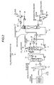
- Fig. 1 is a schematic diagram of a structure of the CO 2 recovering apparatus according to the first embodiment.
- the elements similar to those in CO 2 recovering apparatus shown in Fig. 2 are designated with the same reference numerals, and redundant explanations thereof are omitted.
- Fig. 1 indicates the CO 2 absorber 16 included in the CO 2 recovering apparatus 100.
- the CO 2 recovering apparatus includes: the CO 2 absorber 16 that brings the flue gas 12 containing CO 2 and O 2 into contact with the CO 2 absorbing liquid (hereinafter, also referred to as "absorbing liquid") to reduce the CO 2 contained in the flue gas 12; a regenerator that reduces CO 2 in the CO 2 absorbing liquid (hereinafter, also referred to as "rich solvent”) 17 that has absorbed the CO 2 in the CO 2 absorber 16, and regenerates the CO 2 absorbing liquid 17, so that the regenerated CO 2 absorbing liquid (hereinafter, also referred to as "lean solvent”) 15 having the CO 2 reduced in the regenerator can be reused in the CO 2 absorber 16; and air-bubble gathering member 51 that gathers air bubbles included in the absorbing liquid in a lower liquid reservoir 50 located at the bottom 16a of the CO 2 absorber 16.
- the CO 2 absorber 16 that brings the flue gas 12 containing CO 2 and O 2 into contact with the CO 2 absorbing liquid (hereinafter, also referred to as "absorbing liquid”) to reduce the
- the air-bubble gathering member 51 is arranged so as to be dipped near or below the liquid surface of the lower liquid reservoir 50 located at the bottom 16a of the absorber 16.
- the air-bubble gathering member 51 enables fine air bubbles included in the absorbing liquid, falling down into the lower liquid reservoir 50, to be gathered together. In this manner, the fine air bubbles are gathered into large ones so that the air bubbles floats onto the liquid surface. As a result, the air bubbles are removed from the lower liquid reservoir 50.
- the rich solvent 17 to be sent into the regenerator no longer contains air bubbles, and comes to contain only dissolved oxygen.
- Examples of the air-bubble gathering member 51 include a wire mesh (e.g., a demister that condenses mist in the air) or a fiber bed (e.g., a coalescer that condenses mist in the air).
- a wire mesh e.g., a demister that condenses mist in the air
- a fiber bed e.g., a coalescer that condenses mist in the air
- the examples include a filler or sintered metal.
- the air-bubble gathering member 51 made of such a material, fine air bubbles in the absorbing liquid can be gathered so that the air bubbles float onto the liquid surface.
- oxygen (O 2 ) and nitrogen (N 2 ) that are gas components included in the flue gas 12 can be reduced. In this manner, it is possible to dramatically reduce the amount of such gas components transported to the regenerator.
- the CO 2 recovering apparatus includes the lower liquid reservoir 50 of the CO 2 absorber 16 having the air-bubble gathering member 51. Therefore, the air bubbles can be caught in the absorbing liquid 15 and gathered together to be removed therefrom. As a result, the only oxygen contained in the rich solvent 17 to be sent into the regenerator is that dissolved therein. In this manner, the concentration of oxygen contained in the CO 2 gas recovered from the regenerator can be reduced. Accordingly, sulfur component can be prevented from becoming deposited while the CO 2 gas recovered from the regenerator is compressed. Furthermore, when the CO 2 gas is used for the chemical applications, a problem such as deterioration of a catalyst can be solved.
- the air-bubble gathering member 51 was arranged in the lower liquid reservoir 50 of the CO 2 absorber 16; CO 2 in flue gas was reduced using an amine-based CO 2 absorbing liquid; and the oxygen concentration was measured.
- the test demonstrated that, before installing the air-bubble gathering member 51, the oxygen concentration of the rich solvent 17 was 54 parts per million; on the contrary, after installing the air-bubble gathering member 51 the oxygen concentration of the rich solvent 17 was reduced to approximately 16 parts per million, achieving approximately 70% of oxygen reduction.
- the air-bubble gathering member is provided to gather fine air bubbles included in the CO 2 absorbing liquid falling down into the lower liquid reservoir of the CO 2 absorber. In this manner, the fine air bubbles are gathered into large ones so that the air bubbles floats onto the liquid surface, and removed from the absorbing liquid. As a result, it is possible to dramatically reduce the amount of gas components transported to the regenerator.
Landscapes
- Chemical & Material Sciences (AREA)
- Engineering & Computer Science (AREA)
- Analytical Chemistry (AREA)
- General Chemical & Material Sciences (AREA)
- Oil, Petroleum & Natural Gas (AREA)
- Chemical Kinetics & Catalysis (AREA)
- Treating Waste Gases (AREA)
- Gas Separation By Absorption (AREA)
- Carbon And Carbon Compounds (AREA)
- Degasification And Air Bubble Elimination (AREA)
Applications Claiming Priority (1)
| Application Number | Priority Date | Filing Date | Title |
|---|---|---|---|
| JP2009134947A JP5173941B2 (ja) | 2009-06-04 | 2009-06-04 | Co2回収装置 |
Publications (2)
| Publication Number | Publication Date |
|---|---|
| EP2258461A1 true EP2258461A1 (de) | 2010-12-08 |
| EP2258461B1 EP2258461B1 (de) | 2015-01-07 |
Family
ID=42101335
Family Applications (1)
| Application Number | Title | Priority Date | Filing Date |
|---|---|---|---|
| EP09174655.2A Not-in-force EP2258461B1 (de) | 2009-06-04 | 2009-10-30 | CO2-Rückgewinnungsvorrichtung |
Country Status (5)
| Country | Link |
|---|---|
| US (1) | US8398757B2 (de) |
| EP (1) | EP2258461B1 (de) |
| JP (1) | JP5173941B2 (de) |
| AU (1) | AU2009230803B1 (de) |
| CA (1) | CA2684156C (de) |
Cited By (7)
| Publication number | Priority date | Publication date | Assignee | Title |
|---|---|---|---|---|
| US8192530B2 (en) | 2007-12-13 | 2012-06-05 | Alstom Technology Ltd | System and method for regeneration of an absorbent solution |
| EP2514508A1 (de) * | 2011-04-21 | 2012-10-24 | Mitsubishi Heavy Industries, Ltd. | Kohlendioxidwiederherstellungssystem |
| US8864878B2 (en) | 2011-09-23 | 2014-10-21 | Alstom Technology Ltd | Heat integration of a cement manufacturing plant with an absorption based carbon dioxide capture process |
| US8911538B2 (en) | 2011-12-22 | 2014-12-16 | Alstom Technology Ltd | Method and system for treating an effluent stream generated by a carbon capture system |
| US9028654B2 (en) | 2012-02-29 | 2015-05-12 | Alstom Technology Ltd | Method of treatment of amine waste water and a system for accomplishing the same |
| US9101912B2 (en) | 2012-11-05 | 2015-08-11 | Alstom Technology Ltd | Method for regeneration of solid amine CO2 capture beds |
| US9133407B2 (en) | 2011-02-25 | 2015-09-15 | Alstom Technology Ltd | Systems and processes for removing volatile degradation products produced in gas purification |
Families Citing this family (71)
| Publication number | Priority date | Publication date | Assignee | Title |
|---|---|---|---|---|
| MY156350A (en) | 2008-03-28 | 2016-02-15 | Exxonmobil Upstream Res Co | Low emission power generation and hydrocarbon recovery systems and methods |
| MY153097A (en) | 2008-03-28 | 2014-12-31 | Exxonmobil Upstream Res Co | Low emission power generation and hydrocarbon recovery systems and methods |
| BRPI0920139A2 (pt) | 2008-10-14 | 2015-12-22 | Exxonmobil Upstream Res Co | sistema de combustão, método de controle de combustão, e, sistema de combustor. |
| CN102597418A (zh) | 2009-11-12 | 2012-07-18 | 埃克森美孚上游研究公司 | 低排放发电和烃采收系统及方法 |
| AU2011271636B2 (en) | 2010-07-02 | 2016-03-17 | Exxonmobil Upstream Research Company | Low emission power generation systems and methods |
| CA2801494C (en) | 2010-07-02 | 2018-04-17 | Exxonmobil Upstream Research Company | Stoichiometric combustion of enriched air with exhaust gas recirculation |
| EA029301B1 (ru) | 2010-07-02 | 2018-03-30 | Эксонмобил Апстрим Рисерч Компани | Интегрированные системы для получения со(варианты) и способ производства электроэнергии |
| MY160832A (en) | 2010-07-02 | 2017-03-31 | Exxonmobil Upstream Res Co | Stoichiometric combustion with exhaust gas recirculation and direct contact cooler |
| TWI564474B (zh) | 2011-03-22 | 2017-01-01 | 艾克頌美孚上游研究公司 | 於渦輪系統中控制化學計量燃燒的整合系統和使用彼之產生動力的方法 |
| TWI563165B (en) | 2011-03-22 | 2016-12-21 | Exxonmobil Upstream Res Co | Power generation system and method for generating power |
| TWI563166B (en) | 2011-03-22 | 2016-12-21 | Exxonmobil Upstream Res Co | Integrated generation systems and methods for generating power |
| TWI593872B (zh) | 2011-03-22 | 2017-08-01 | 艾克頌美孚上游研究公司 | 整合系統及產生動力之方法 |
| US9492786B2 (en) * | 2011-11-22 | 2016-11-15 | Fluor Corporation | Multi-purpose absorber |
| CN104428490B (zh) | 2011-12-20 | 2018-06-05 | 埃克森美孚上游研究公司 | 提高的煤层甲烷生产 |
| US9353682B2 (en) | 2012-04-12 | 2016-05-31 | General Electric Company | Methods, systems and apparatus relating to combustion turbine power plants with exhaust gas recirculation |
| US9784185B2 (en) | 2012-04-26 | 2017-10-10 | General Electric Company | System and method for cooling a gas turbine with an exhaust gas provided by the gas turbine |
| US10273880B2 (en) | 2012-04-26 | 2019-04-30 | General Electric Company | System and method of recirculating exhaust gas for use in a plurality of flow paths in a gas turbine engine |
| US9869279B2 (en) | 2012-11-02 | 2018-01-16 | General Electric Company | System and method for a multi-wall turbine combustor |
| US9599070B2 (en) | 2012-11-02 | 2017-03-21 | General Electric Company | System and method for oxidant compression in a stoichiometric exhaust gas recirculation gas turbine system |
| US9708977B2 (en) | 2012-12-28 | 2017-07-18 | General Electric Company | System and method for reheat in gas turbine with exhaust gas recirculation |
| US9611756B2 (en) | 2012-11-02 | 2017-04-04 | General Electric Company | System and method for protecting components in a gas turbine engine with exhaust gas recirculation |
| US10215412B2 (en) | 2012-11-02 | 2019-02-26 | General Electric Company | System and method for load control with diffusion combustion in a stoichiometric exhaust gas recirculation gas turbine system |
| US9631815B2 (en) | 2012-12-28 | 2017-04-25 | General Electric Company | System and method for a turbine combustor |
| US10100741B2 (en) | 2012-11-02 | 2018-10-16 | General Electric Company | System and method for diffusion combustion with oxidant-diluent mixing in a stoichiometric exhaust gas recirculation gas turbine system |
| US9574496B2 (en) | 2012-12-28 | 2017-02-21 | General Electric Company | System and method for a turbine combustor |
| US9803865B2 (en) | 2012-12-28 | 2017-10-31 | General Electric Company | System and method for a turbine combustor |
| US10107495B2 (en) | 2012-11-02 | 2018-10-23 | General Electric Company | Gas turbine combustor control system for stoichiometric combustion in the presence of a diluent |
| US10208677B2 (en) | 2012-12-31 | 2019-02-19 | General Electric Company | Gas turbine load control system |
| US9581081B2 (en) | 2013-01-13 | 2017-02-28 | General Electric Company | System and method for protecting components in a gas turbine engine with exhaust gas recirculation |
| US9512759B2 (en) | 2013-02-06 | 2016-12-06 | General Electric Company | System and method for catalyst heat utilization for gas turbine with exhaust gas recirculation |
| US9938861B2 (en) | 2013-02-21 | 2018-04-10 | Exxonmobil Upstream Research Company | Fuel combusting method |
| TW201502356A (zh) | 2013-02-21 | 2015-01-16 | Exxonmobil Upstream Res Co | 氣渦輪機排氣中氧之減少 |
| RU2637609C2 (ru) | 2013-02-28 | 2017-12-05 | Эксонмобил Апстрим Рисерч Компани | Система и способ для камеры сгорания турбины |
| TW201500635A (zh) | 2013-03-08 | 2015-01-01 | Exxonmobil Upstream Res Co | 處理廢氣以供用於提高油回收 |
| US9618261B2 (en) | 2013-03-08 | 2017-04-11 | Exxonmobil Upstream Research Company | Power generation and LNG production |
| WO2014137648A1 (en) | 2013-03-08 | 2014-09-12 | Exxonmobil Upstream Research Company | Power generation and methane recovery from methane hydrates |
| US20140250945A1 (en) | 2013-03-08 | 2014-09-11 | Richard A. Huntington | Carbon Dioxide Recovery |
| TWI654368B (zh) | 2013-06-28 | 2019-03-21 | 美商艾克頌美孚上游研究公司 | 用於控制在廢氣再循環氣渦輪機系統中的廢氣流之系統、方法與媒體 |
| US9835089B2 (en) | 2013-06-28 | 2017-12-05 | General Electric Company | System and method for a fuel nozzle |
| US9631542B2 (en) | 2013-06-28 | 2017-04-25 | General Electric Company | System and method for exhausting combustion gases from gas turbine engines |
| US9617914B2 (en) | 2013-06-28 | 2017-04-11 | General Electric Company | Systems and methods for monitoring gas turbine systems having exhaust gas recirculation |
| US9265267B2 (en) | 2013-07-22 | 2016-02-23 | Garry Parkinson Isaacs | Open top liquid/gas cyclone separator tube and process for same |
| US9587510B2 (en) | 2013-07-30 | 2017-03-07 | General Electric Company | System and method for a gas turbine engine sensor |
| US9903588B2 (en) | 2013-07-30 | 2018-02-27 | General Electric Company | System and method for barrier in passage of combustor of gas turbine engine with exhaust gas recirculation |
| US9951658B2 (en) | 2013-07-31 | 2018-04-24 | General Electric Company | System and method for an oxidant heating system |
| US10030588B2 (en) | 2013-12-04 | 2018-07-24 | General Electric Company | Gas turbine combustor diagnostic system and method |
| US9752458B2 (en) | 2013-12-04 | 2017-09-05 | General Electric Company | System and method for a gas turbine engine |
| US10227920B2 (en) | 2014-01-15 | 2019-03-12 | General Electric Company | Gas turbine oxidant separation system |
| US9863267B2 (en) | 2014-01-21 | 2018-01-09 | General Electric Company | System and method of control for a gas turbine engine |
| US9915200B2 (en) | 2014-01-21 | 2018-03-13 | General Electric Company | System and method for controlling the combustion process in a gas turbine operating with exhaust gas recirculation |
| US10079564B2 (en) | 2014-01-27 | 2018-09-18 | General Electric Company | System and method for a stoichiometric exhaust gas recirculation gas turbine system |
| US10047633B2 (en) | 2014-05-16 | 2018-08-14 | General Electric Company | Bearing housing |
| US10060359B2 (en) | 2014-06-30 | 2018-08-28 | General Electric Company | Method and system for combustion control for gas turbine system with exhaust gas recirculation |
| US10655542B2 (en) | 2014-06-30 | 2020-05-19 | General Electric Company | Method and system for startup of gas turbine system drive trains with exhaust gas recirculation |
| US9885290B2 (en) | 2014-06-30 | 2018-02-06 | General Electric Company | Erosion suppression system and method in an exhaust gas recirculation gas turbine system |
| US9819292B2 (en) | 2014-12-31 | 2017-11-14 | General Electric Company | Systems and methods to respond to grid overfrequency events for a stoichiometric exhaust recirculation gas turbine |
| US9869247B2 (en) | 2014-12-31 | 2018-01-16 | General Electric Company | Systems and methods of estimating a combustion equivalence ratio in a gas turbine with exhaust gas recirculation |
| US10788212B2 (en) | 2015-01-12 | 2020-09-29 | General Electric Company | System and method for an oxidant passageway in a gas turbine system with exhaust gas recirculation |
| US10253690B2 (en) | 2015-02-04 | 2019-04-09 | General Electric Company | Turbine system with exhaust gas recirculation, separation and extraction |
| US10316746B2 (en) | 2015-02-04 | 2019-06-11 | General Electric Company | Turbine system with exhaust gas recirculation, separation and extraction |
| US10094566B2 (en) | 2015-02-04 | 2018-10-09 | General Electric Company | Systems and methods for high volumetric oxidant flow in gas turbine engine with exhaust gas recirculation |
| US10267270B2 (en) | 2015-02-06 | 2019-04-23 | General Electric Company | Systems and methods for carbon black production with a gas turbine engine having exhaust gas recirculation |
| US10145269B2 (en) | 2015-03-04 | 2018-12-04 | General Electric Company | System and method for cooling discharge flow |
| US10480792B2 (en) | 2015-03-06 | 2019-11-19 | General Electric Company | Fuel staging in a gas turbine engine |
| US9962656B2 (en) | 2016-09-21 | 2018-05-08 | Nrgtek, Inc. | Method of using new solvents for forward osmosis |
| US9782719B1 (en) | 2016-08-09 | 2017-10-10 | Nrgtek, Inc. | Solvents and methods for gas separation from gas streams |
| CN105413411A (zh) * | 2016-01-12 | 2016-03-23 | 广西新天德能源有限公司 | 食用级二氧化碳精洗塔 |
| US9956522B2 (en) | 2016-08-09 | 2018-05-01 | Nrgtek, Inc. | Moisture removal from wet gases |
| US10143970B2 (en) | 2016-08-09 | 2018-12-04 | Nrgtek, Inc. | Power generation from low-temperature heat by hydro-osmotic processes |
| KR101859511B1 (ko) * | 2016-08-19 | 2018-05-23 | 한국에너지기술연구원 | 소포기가 구비된 혼합액 분리장치 |
| US10819944B2 (en) | 2016-12-16 | 2020-10-27 | Seagate Technology Llc | Mobile wireless drive storage for mobile phone used as car dashboard camera |
Citations (9)
| Publication number | Priority date | Publication date | Assignee | Title |
|---|---|---|---|---|
| US3516799A (en) * | 1967-02-02 | 1970-06-23 | Dow Chemical Co | Liquid degassing apparatus |
| GB2096916A (en) * | 1981-04-21 | 1982-10-27 | Uemura Kogyo Kk | Degassing assembly |
| JPH03193116A (ja) | 1989-12-25 | 1991-08-22 | Mitsubishi Heavy Ind Ltd | 燃焼排ガス中のco↓2の除去方法 |
| US6146603A (en) * | 1999-06-10 | 2000-11-14 | Praxair Technology, Inc. | System for recovering carbon dioxide from a lean feed |
| DE10002982A1 (de) * | 2000-01-24 | 2001-08-02 | Pannenborg Jens | Verfahren zur Filtration unter Vakuum in druckausgeglichenen Strömungssystemen |
| US20010026779A1 (en) * | 1999-06-10 | 2001-10-04 | Shrikar Chakravarti | Carbon dioxide recovery plant |
| US6689332B1 (en) * | 1992-09-16 | 2004-02-10 | The Kansai Electric Power Co, Inc. | Process for removing carbon dioxide from combustion gases |
| DE10310395A1 (de) * | 2003-03-07 | 2004-09-23 | Enginion Ag | Vorrichtung zur Entgasung von Speisewasser |
| US20050155925A1 (en) * | 2004-01-21 | 2005-07-21 | Thrush Co., Inc. | Apparatus for removing air and/or debris from a flow of liquid |
Family Cites Families (10)
| Publication number | Priority date | Publication date | Assignee | Title |
|---|---|---|---|---|
| US3075914A (en) * | 1960-08-18 | 1963-01-29 | Standard Oil Co | Liquid phase contacting of hydrocarbons |
| JPS6358611U (de) * | 1986-10-03 | 1988-04-19 | ||
| CA2177449C (en) * | 1996-05-20 | 2003-04-29 | Barry Steve Marjanovich | Process for treating a gas stream to selectively separate acid gases therefrom |
| US6174506B1 (en) * | 1999-06-10 | 2001-01-16 | Praxair Technology, Inc. | Carbon dioxide recovery from an oxygen containing mixture |
| NL1015827C2 (nl) * | 2000-07-27 | 2002-02-01 | Continental Engineering B V | Winning van zuiver CO2 uit rookgassen. |
| US6582498B1 (en) * | 2001-05-04 | 2003-06-24 | Battelle Memorial Institute | Method of separating carbon dioxide from a gas mixture using a fluid dynamic instability |
| NZ514666A (en) * | 2001-10-08 | 2003-01-31 | Canterprise Ltd | Apparatus for continuous carbon dioxide absorption comprising a reactor containing a carbon dioxide absorbent liquid recycled via a regenerator |
| US7326333B2 (en) * | 2001-12-20 | 2008-02-05 | Uop Llc | Apparatus and process for extracting sulfur compounds from a hydrocarbon stream |
| JP2007137725A (ja) * | 2005-11-18 | 2007-06-07 | Toshiba Corp | 二酸化炭素回収システムおよび二酸化炭素回収方法 |
| WO2009091437A1 (en) * | 2008-01-18 | 2009-07-23 | Powerspan Corp. | Removal of carbon dioxide from a flue gas stream |
-
2009
- 2009-06-04 JP JP2009134947A patent/JP5173941B2/ja not_active Expired - Fee Related
- 2009-10-28 AU AU2009230803A patent/AU2009230803B1/en not_active Ceased
- 2009-10-29 CA CA2684156A patent/CA2684156C/en not_active Expired - Fee Related
- 2009-10-29 US US12/608,286 patent/US8398757B2/en not_active Expired - Fee Related
- 2009-10-30 EP EP09174655.2A patent/EP2258461B1/de not_active Not-in-force
Patent Citations (10)
| Publication number | Priority date | Publication date | Assignee | Title |
|---|---|---|---|---|
| US3516799A (en) * | 1967-02-02 | 1970-06-23 | Dow Chemical Co | Liquid degassing apparatus |
| GB2096916A (en) * | 1981-04-21 | 1982-10-27 | Uemura Kogyo Kk | Degassing assembly |
| JPH03193116A (ja) | 1989-12-25 | 1991-08-22 | Mitsubishi Heavy Ind Ltd | 燃焼排ガス中のco↓2の除去方法 |
| US6689332B1 (en) * | 1992-09-16 | 2004-02-10 | The Kansai Electric Power Co, Inc. | Process for removing carbon dioxide from combustion gases |
| US6146603A (en) * | 1999-06-10 | 2000-11-14 | Praxair Technology, Inc. | System for recovering carbon dioxide from a lean feed |
| US20010026779A1 (en) * | 1999-06-10 | 2001-10-04 | Shrikar Chakravarti | Carbon dioxide recovery plant |
| DE10002982A1 (de) * | 2000-01-24 | 2001-08-02 | Pannenborg Jens | Verfahren zur Filtration unter Vakuum in druckausgeglichenen Strömungssystemen |
| JP2004524147A (ja) | 2001-01-31 | 2004-08-12 | プラクスエア・テクノロジー・インコーポレイテッド | 二酸化炭素回収プラント |
| DE10310395A1 (de) * | 2003-03-07 | 2004-09-23 | Enginion Ag | Vorrichtung zur Entgasung von Speisewasser |
| US20050155925A1 (en) * | 2004-01-21 | 2005-07-21 | Thrush Co., Inc. | Apparatus for removing air and/or debris from a flow of liquid |
Cited By (8)
| Publication number | Priority date | Publication date | Assignee | Title |
|---|---|---|---|---|
| US8192530B2 (en) | 2007-12-13 | 2012-06-05 | Alstom Technology Ltd | System and method for regeneration of an absorbent solution |
| US9133407B2 (en) | 2011-02-25 | 2015-09-15 | Alstom Technology Ltd | Systems and processes for removing volatile degradation products produced in gas purification |
| EP2514508A1 (de) * | 2011-04-21 | 2012-10-24 | Mitsubishi Heavy Industries, Ltd. | Kohlendioxidwiederherstellungssystem |
| US8845797B2 (en) | 2011-04-21 | 2014-09-30 | Mitsubishi Heavy Industries, Ltd. | Carbon dioxide recovery system |
| US8864878B2 (en) | 2011-09-23 | 2014-10-21 | Alstom Technology Ltd | Heat integration of a cement manufacturing plant with an absorption based carbon dioxide capture process |
| US8911538B2 (en) | 2011-12-22 | 2014-12-16 | Alstom Technology Ltd | Method and system for treating an effluent stream generated by a carbon capture system |
| US9028654B2 (en) | 2012-02-29 | 2015-05-12 | Alstom Technology Ltd | Method of treatment of amine waste water and a system for accomplishing the same |
| US9101912B2 (en) | 2012-11-05 | 2015-08-11 | Alstom Technology Ltd | Method for regeneration of solid amine CO2 capture beds |
Also Published As
| Publication number | Publication date |
|---|---|
| AU2009230803B1 (en) | 2010-12-16 |
| EP2258461B1 (de) | 2015-01-07 |
| US20100307344A1 (en) | 2010-12-09 |
| CA2684156A1 (en) | 2010-12-04 |
| JP5173941B2 (ja) | 2013-04-03 |
| US8398757B2 (en) | 2013-03-19 |
| CA2684156C (en) | 2012-06-26 |
| JP2010279897A (ja) | 2010-12-16 |
Similar Documents
| Publication | Publication Date | Title |
|---|---|---|
| EP2258461B1 (de) | CO2-Rückgewinnungsvorrichtung | |
| US8377184B2 (en) | CO2 recovery apparatus and CO2 recovery method | |
| EP2829311B1 (de) | Ammoniakstripper für ein Kohlenstoffabscheidungssystem zur Reduzierung des Energieverbrauchs | |
| JP6016513B2 (ja) | Co2回収装置およびco2回収方法 | |
| EP1970115B1 (de) | System zur Zurückgewinnung von Kohlendioxid und Verfahren zur Entfernung von Abfallprodukten | |
| EP2269711A1 (de) | CO2-Rückgewinnungsvorrichtung und Verfahren | |
| JP6071838B2 (ja) | Co2又はh2s又はその双方の回収装置及び方法 | |
| JP6057545B2 (ja) | 排ガス処理装置 | |
| EP2230000A1 (de) | Vorrichtung und Verfahren zur Abgasbehandlung mit Ammoniaklösung | |
| WO2010122830A1 (ja) | Co2回収装置及びco2回収方法 | |
| JP5931834B2 (ja) | リクレーミング装置及び方法、co2又はh2s又はその双方の回収装置 | |
| EP2537574A1 (de) | Luftverschmutzungskontrollsystem und Luftverschmutzungskontrollverfahren | |
| KR101726162B1 (ko) | 산성가스 포집을 위한 탈거장치의 에너지원 재사용 방법 | |
| US20260048360A1 (en) | Systems and methods for removing carbon dioxide from a carbon dioxide containing gas using a geothermal energy source |
Legal Events
| Date | Code | Title | Description |
|---|---|---|---|
| PUAI | Public reference made under article 153(3) epc to a published international application that has entered the european phase |
Free format text: ORIGINAL CODE: 0009012 |
|
| AK | Designated contracting states |
Kind code of ref document: A1 Designated state(s): AT BE BG CH CY CZ DE DK EE ES FI FR GB GR HR HU IE IS IT LI LT LU LV MC MK MT NL NO PL PT RO SE SI SK SM TR |
|
| AX | Request for extension of the european patent |
Extension state: AL BA RS |
|
| 17P | Request for examination filed |
Effective date: 20110608 |
|
| GRAP | Despatch of communication of intention to grant a patent |
Free format text: ORIGINAL CODE: EPIDOSNIGR1 |
|
| RIC1 | Information provided on ipc code assigned before grant |
Ipc: B01D 53/14 20060101AFI20140911BHEP Ipc: B01D 19/00 20060101ALI20140911BHEP Ipc: B01D 53/62 20060101ALI20140911BHEP Ipc: B01D 53/18 20060101ALI20140911BHEP |
|
| INTG | Intention to grant announced |
Effective date: 20140929 |
|
| GRAS | Grant fee paid |
Free format text: ORIGINAL CODE: EPIDOSNIGR3 |
|
| GRAA | (expected) grant |
Free format text: ORIGINAL CODE: 0009210 |
|
| AK | Designated contracting states |
Kind code of ref document: B1 Designated state(s): AT BE BG CH CY CZ DE DK EE ES FI FR GB GR HR HU IE IS IT LI LT LU LV MC MK MT NL NO PL PT RO SE SI SK SM TR |
|
| REG | Reference to a national code |
Ref country code: GB Ref legal event code: FG4D |
|
| REG | Reference to a national code |
Ref country code: CH Ref legal event code: EP |
|
| REG | Reference to a national code |
Ref country code: IE Ref legal event code: FG4D |
|
| REG | Reference to a national code |
Ref country code: AT Ref legal event code: REF Ref document number: 705295 Country of ref document: AT Kind code of ref document: T Effective date: 20150215 |
|
| REG | Reference to a national code |
Ref country code: DE Ref legal event code: R096 Ref document number: 602009028789 Country of ref document: DE Effective date: 20150226 |
|
| REG | Reference to a national code |
Ref country code: NO Ref legal event code: T2 Effective date: 20150107 |
|
| REG | Reference to a national code |
Ref country code: NL Ref legal event code: VDEP Effective date: 20150107 |
|
| REG | Reference to a national code |
Ref country code: AT Ref legal event code: MK05 Ref document number: 705295 Country of ref document: AT Kind code of ref document: T Effective date: 20150107 |
|
| REG | Reference to a national code |
Ref country code: LT Ref legal event code: MG4D |
|
| PG25 | Lapsed in a contracting state [announced via postgrant information from national office to epo] |
Ref country code: FI Free format text: LAPSE BECAUSE OF FAILURE TO SUBMIT A TRANSLATION OF THE DESCRIPTION OR TO PAY THE FEE WITHIN THE PRESCRIBED TIME-LIMIT Effective date: 20150107 Ref country code: SE Free format text: LAPSE BECAUSE OF FAILURE TO SUBMIT A TRANSLATION OF THE DESCRIPTION OR TO PAY THE FEE WITHIN THE PRESCRIBED TIME-LIMIT Effective date: 20150107 Ref country code: BG Free format text: LAPSE BECAUSE OF FAILURE TO SUBMIT A TRANSLATION OF THE DESCRIPTION OR TO PAY THE FEE WITHIN THE PRESCRIBED TIME-LIMIT Effective date: 20150407 Ref country code: HR Free format text: LAPSE BECAUSE OF FAILURE TO SUBMIT A TRANSLATION OF THE DESCRIPTION OR TO PAY THE FEE WITHIN THE PRESCRIBED TIME-LIMIT Effective date: 20150107 Ref country code: LT Free format text: LAPSE BECAUSE OF FAILURE TO SUBMIT A TRANSLATION OF THE DESCRIPTION OR TO PAY THE FEE WITHIN THE PRESCRIBED TIME-LIMIT Effective date: 20150107 Ref country code: ES Free format text: LAPSE BECAUSE OF FAILURE TO SUBMIT A TRANSLATION OF THE DESCRIPTION OR TO PAY THE FEE WITHIN THE PRESCRIBED TIME-LIMIT Effective date: 20150107 |
|
| PG25 | Lapsed in a contracting state [announced via postgrant information from national office to epo] |
Ref country code: NL Free format text: LAPSE BECAUSE OF FAILURE TO SUBMIT A TRANSLATION OF THE DESCRIPTION OR TO PAY THE FEE WITHIN THE PRESCRIBED TIME-LIMIT Effective date: 20150107 Ref country code: GR Free format text: LAPSE BECAUSE OF FAILURE TO SUBMIT A TRANSLATION OF THE DESCRIPTION OR TO PAY THE FEE WITHIN THE PRESCRIBED TIME-LIMIT Effective date: 20150408 Ref country code: PL Free format text: LAPSE BECAUSE OF FAILURE TO SUBMIT A TRANSLATION OF THE DESCRIPTION OR TO PAY THE FEE WITHIN THE PRESCRIBED TIME-LIMIT Effective date: 20150107 Ref country code: AT Free format text: LAPSE BECAUSE OF FAILURE TO SUBMIT A TRANSLATION OF THE DESCRIPTION OR TO PAY THE FEE WITHIN THE PRESCRIBED TIME-LIMIT Effective date: 20150107 Ref country code: LV Free format text: LAPSE BECAUSE OF FAILURE TO SUBMIT A TRANSLATION OF THE DESCRIPTION OR TO PAY THE FEE WITHIN THE PRESCRIBED TIME-LIMIT Effective date: 20150107 Ref country code: IS Free format text: LAPSE BECAUSE OF FAILURE TO SUBMIT A TRANSLATION OF THE DESCRIPTION OR TO PAY THE FEE WITHIN THE PRESCRIBED TIME-LIMIT Effective date: 20150507 |
|
| REG | Reference to a national code |
Ref country code: DE Ref legal event code: R097 Ref document number: 602009028789 Country of ref document: DE |
|
| PG25 | Lapsed in a contracting state [announced via postgrant information from national office to epo] |
Ref country code: CZ Free format text: LAPSE BECAUSE OF FAILURE TO SUBMIT A TRANSLATION OF THE DESCRIPTION OR TO PAY THE FEE WITHIN THE PRESCRIBED TIME-LIMIT Effective date: 20150107 Ref country code: SK Free format text: LAPSE BECAUSE OF FAILURE TO SUBMIT A TRANSLATION OF THE DESCRIPTION OR TO PAY THE FEE WITHIN THE PRESCRIBED TIME-LIMIT Effective date: 20150107 Ref country code: DK Free format text: LAPSE BECAUSE OF FAILURE TO SUBMIT A TRANSLATION OF THE DESCRIPTION OR TO PAY THE FEE WITHIN THE PRESCRIBED TIME-LIMIT Effective date: 20150107 Ref country code: EE Free format text: LAPSE BECAUSE OF FAILURE TO SUBMIT A TRANSLATION OF THE DESCRIPTION OR TO PAY THE FEE WITHIN THE PRESCRIBED TIME-LIMIT Effective date: 20150107 Ref country code: RO Free format text: LAPSE BECAUSE OF FAILURE TO SUBMIT A TRANSLATION OF THE DESCRIPTION OR TO PAY THE FEE WITHIN THE PRESCRIBED TIME-LIMIT Effective date: 20150107 |
|
| PLBE | No opposition filed within time limit |
Free format text: ORIGINAL CODE: 0009261 |
|
| STAA | Information on the status of an ep patent application or granted ep patent |
Free format text: STATUS: NO OPPOSITION FILED WITHIN TIME LIMIT |
|
| 26N | No opposition filed |
Effective date: 20151008 |
|
| PG25 | Lapsed in a contracting state [announced via postgrant information from national office to epo] |
Ref country code: SI Free format text: LAPSE BECAUSE OF FAILURE TO SUBMIT A TRANSLATION OF THE DESCRIPTION OR TO PAY THE FEE WITHIN THE PRESCRIBED TIME-LIMIT Effective date: 20150107 |
|
| PG25 | Lapsed in a contracting state [announced via postgrant information from national office to epo] |
Ref country code: BE Free format text: LAPSE BECAUSE OF FAILURE TO SUBMIT A TRANSLATION OF THE DESCRIPTION OR TO PAY THE FEE WITHIN THE PRESCRIBED TIME-LIMIT Effective date: 20150107 Ref country code: LU Free format text: LAPSE BECAUSE OF FAILURE TO SUBMIT A TRANSLATION OF THE DESCRIPTION OR TO PAY THE FEE WITHIN THE PRESCRIBED TIME-LIMIT Effective date: 20151030 |
|
| REG | Reference to a national code |
Ref country code: CH Ref legal event code: PL |
|
| PG25 | Lapsed in a contracting state [announced via postgrant information from national office to epo] |
Ref country code: MC Free format text: LAPSE BECAUSE OF FAILURE TO SUBMIT A TRANSLATION OF THE DESCRIPTION OR TO PAY THE FEE WITHIN THE PRESCRIBED TIME-LIMIT Effective date: 20150107 |
|
| REG | Reference to a national code |
Ref country code: IE Ref legal event code: MM4A |
|
| PG25 | Lapsed in a contracting state [announced via postgrant information from national office to epo] |
Ref country code: CH Free format text: LAPSE BECAUSE OF NON-PAYMENT OF DUE FEES Effective date: 20151031 Ref country code: LI Free format text: LAPSE BECAUSE OF NON-PAYMENT OF DUE FEES Effective date: 20151031 |
|
| REG | Reference to a national code |
Ref country code: FR Ref legal event code: ST Effective date: 20160630 |
|
| PG25 | Lapsed in a contracting state [announced via postgrant information from national office to epo] |
Ref country code: FR Free format text: LAPSE BECAUSE OF NON-PAYMENT OF DUE FEES Effective date: 20151102 |
|
| PG25 | Lapsed in a contracting state [announced via postgrant information from national office to epo] |
Ref country code: IE Free format text: LAPSE BECAUSE OF NON-PAYMENT OF DUE FEES Effective date: 20151030 |
|
| PG25 | Lapsed in a contracting state [announced via postgrant information from national office to epo] |
Ref country code: SM Free format text: LAPSE BECAUSE OF FAILURE TO SUBMIT A TRANSLATION OF THE DESCRIPTION OR TO PAY THE FEE WITHIN THE PRESCRIBED TIME-LIMIT Effective date: 20150107 Ref country code: HU Free format text: LAPSE BECAUSE OF FAILURE TO SUBMIT A TRANSLATION OF THE DESCRIPTION OR TO PAY THE FEE WITHIN THE PRESCRIBED TIME-LIMIT; INVALID AB INITIO Effective date: 20091030 |
|
| PG25 | Lapsed in a contracting state [announced via postgrant information from national office to epo] |
Ref country code: CY Free format text: LAPSE BECAUSE OF FAILURE TO SUBMIT A TRANSLATION OF THE DESCRIPTION OR TO PAY THE FEE WITHIN THE PRESCRIBED TIME-LIMIT Effective date: 20150107 |
|
| PG25 | Lapsed in a contracting state [announced via postgrant information from national office to epo] |
Ref country code: MT Free format text: LAPSE BECAUSE OF FAILURE TO SUBMIT A TRANSLATION OF THE DESCRIPTION OR TO PAY THE FEE WITHIN THE PRESCRIBED TIME-LIMIT Effective date: 20150107 Ref country code: TR Free format text: LAPSE BECAUSE OF FAILURE TO SUBMIT A TRANSLATION OF THE DESCRIPTION OR TO PAY THE FEE WITHIN THE PRESCRIBED TIME-LIMIT Effective date: 20150107 |
|
| PGFP | Annual fee paid to national office [announced via postgrant information from national office to epo] |
Ref country code: NO Payment date: 20171010 Year of fee payment: 9 Ref country code: DE Payment date: 20171025 Year of fee payment: 9 |
|
| PGFP | Annual fee paid to national office [announced via postgrant information from national office to epo] |
Ref country code: GB Payment date: 20171025 Year of fee payment: 9 Ref country code: IT Payment date: 20171024 Year of fee payment: 9 |
|
| PG25 | Lapsed in a contracting state [announced via postgrant information from national office to epo] |
Ref country code: MK Free format text: LAPSE BECAUSE OF FAILURE TO SUBMIT A TRANSLATION OF THE DESCRIPTION OR TO PAY THE FEE WITHIN THE PRESCRIBED TIME-LIMIT Effective date: 20150107 Ref country code: PT Free format text: LAPSE BECAUSE OF FAILURE TO SUBMIT A TRANSLATION OF THE DESCRIPTION OR TO PAY THE FEE WITHIN THE PRESCRIBED TIME-LIMIT Effective date: 20150107 |
|
| REG | Reference to a national code |
Ref country code: DE Ref legal event code: R119 Ref document number: 602009028789 Country of ref document: DE |
|
| REG | Reference to a national code |
Ref country code: NO Ref legal event code: MMEP |
|
| GBPC | Gb: european patent ceased through non-payment of renewal fee |
Effective date: 20181030 |
|
| PG25 | Lapsed in a contracting state [announced via postgrant information from national office to epo] |
Ref country code: NO Free format text: LAPSE BECAUSE OF NON-PAYMENT OF DUE FEES Effective date: 20181031 Ref country code: DE Free format text: LAPSE BECAUSE OF NON-PAYMENT OF DUE FEES Effective date: 20190501 |
|
| PG25 | Lapsed in a contracting state [announced via postgrant information from national office to epo] |
Ref country code: GB Free format text: LAPSE BECAUSE OF NON-PAYMENT OF DUE FEES Effective date: 20181030 Ref country code: IT Free format text: LAPSE BECAUSE OF NON-PAYMENT OF DUE FEES Effective date: 20181030 |