EP2258480A2 - Plaque détachable pour protéger le drainage d'un appareil d'essai multipuits - Google Patents
Plaque détachable pour protéger le drainage d'un appareil d'essai multipuits Download PDFInfo
- Publication number
- EP2258480A2 EP2258480A2 EP10178410A EP10178410A EP2258480A2 EP 2258480 A2 EP2258480 A2 EP 2258480A2 EP 10178410 A EP10178410 A EP 10178410A EP 10178410 A EP10178410 A EP 10178410A EP 2258480 A2 EP2258480 A2 EP 2258480A2
- Authority
- EP
- European Patent Office
- Prior art keywords
- plate
- microarray
- spout
- plate liner
- liner
- Prior art date
- Legal status (The legal status is an assumption and is not a legal conclusion. Google has not performed a legal analysis and makes no representation as to the accuracy of the status listed.)
- Withdrawn
Links
- 238000002493 microarray Methods 0.000 title claims abstract description 64
- 230000015572 biosynthetic process Effects 0.000 claims abstract description 17
- 239000012530 fluid Substances 0.000 claims description 55
- 239000000463 material Substances 0.000 claims description 43
- 230000003287 optical effect Effects 0.000 claims description 13
- 230000008878 coupling Effects 0.000 claims description 11
- 238000010168 coupling process Methods 0.000 claims description 11
- 238000005859 coupling reaction Methods 0.000 claims description 11
- 238000011144 upstream manufacturing Methods 0.000 claims description 4
- 230000000694 effects Effects 0.000 claims description 3
- 238000004806 packaging method and process Methods 0.000 claims description 3
- 238000001914 filtration Methods 0.000 abstract description 21
- 238000000926 separation method Methods 0.000 description 24
- 239000012528 membrane Substances 0.000 description 14
- 230000001681 protective effect Effects 0.000 description 14
- 238000013459 approach Methods 0.000 description 10
- 238000000034 method Methods 0.000 description 8
- 230000008901 benefit Effects 0.000 description 7
- 239000007788 liquid Substances 0.000 description 7
- 239000000853 adhesive Substances 0.000 description 5
- 230000001070 adhesive effect Effects 0.000 description 5
- 238000011534 incubation Methods 0.000 description 5
- 230000037361 pathway Effects 0.000 description 5
- 229920000642 polymer Polymers 0.000 description 5
- 239000000126 substance Substances 0.000 description 5
- 238000010276 construction Methods 0.000 description 4
- 229920001577 copolymer Polymers 0.000 description 4
- 230000002093 peripheral effect Effects 0.000 description 4
- 125000006850 spacer group Chemical group 0.000 description 4
- 238000011282 treatment Methods 0.000 description 4
- 238000004458 analytical method Methods 0.000 description 3
- 238000003556 assay Methods 0.000 description 3
- 238000011109 contamination Methods 0.000 description 3
- 239000000975 dye Substances 0.000 description 3
- 239000000706 filtrate Substances 0.000 description 3
- 239000004417 polycarbonate Substances 0.000 description 3
- 229920000515 polycarbonate Polymers 0.000 description 3
- 229920000098 polyolefin Polymers 0.000 description 3
- 230000008569 process Effects 0.000 description 3
- 238000004659 sterilization and disinfection Methods 0.000 description 3
- 238000003860 storage Methods 0.000 description 3
- 229920001187 thermosetting polymer Polymers 0.000 description 3
- 241000894006 Bacteria Species 0.000 description 2
- 239000002033 PVDF binder Substances 0.000 description 2
- 239000004793 Polystyrene Substances 0.000 description 2
- PPBRXRYQALVLMV-UHFFFAOYSA-N Styrene Chemical compound C=CC1=CC=CC=C1 PPBRXRYQALVLMV-UHFFFAOYSA-N 0.000 description 2
- GWEVSGVZZGPLCZ-UHFFFAOYSA-N Titan oxide Chemical compound O=[Ti]=O GWEVSGVZZGPLCZ-UHFFFAOYSA-N 0.000 description 2
- 239000011358 absorbing material Substances 0.000 description 2
- 239000011324 bead Substances 0.000 description 2
- 230000005540 biological transmission Effects 0.000 description 2
- 229960000074 biopharmaceutical Drugs 0.000 description 2
- 239000003153 chemical reaction reagent Substances 0.000 description 2
- 238000000576 coating method Methods 0.000 description 2
- 230000000295 complement effect Effects 0.000 description 2
- 238000012864 cross contamination Methods 0.000 description 2
- 238000005520 cutting process Methods 0.000 description 2
- 238000013461 design Methods 0.000 description 2
- 239000013536 elastomeric material Substances 0.000 description 2
- 239000000945 filler Substances 0.000 description 2
- 238000007689 inspection Methods 0.000 description 2
- 238000004519 manufacturing process Methods 0.000 description 2
- 238000012986 modification Methods 0.000 description 2
- 230000004048 modification Effects 0.000 description 2
- 239000000049 pigment Substances 0.000 description 2
- 229920002492 poly(sulfone) Polymers 0.000 description 2
- -1 polypropylene Polymers 0.000 description 2
- 229920002223 polystyrene Polymers 0.000 description 2
- 229920002981 polyvinylidene fluoride Polymers 0.000 description 2
- 230000002028 premature Effects 0.000 description 2
- 238000003825 pressing Methods 0.000 description 2
- 230000002265 prevention Effects 0.000 description 2
- 238000012545 processing Methods 0.000 description 2
- 230000001737 promoting effect Effects 0.000 description 2
- 102000004169 proteins and genes Human genes 0.000 description 2
- 108090000623 proteins and genes Proteins 0.000 description 2
- 238000011160 research Methods 0.000 description 2
- 229920005989 resin Polymers 0.000 description 2
- 239000011347 resin Substances 0.000 description 2
- 230000000717 retained effect Effects 0.000 description 2
- 230000001954 sterilising effect Effects 0.000 description 2
- 229920001169 thermoplastic Polymers 0.000 description 2
- 239000004416 thermosoftening plastic Substances 0.000 description 2
- 238000000108 ultra-filtration Methods 0.000 description 2
- 239000000020 Nitrocellulose Substances 0.000 description 1
- 239000004698 Polyethylene Substances 0.000 description 1
- 239000004743 Polypropylene Substances 0.000 description 1
- 239000004699 Ultra-high molecular weight polyethylene Substances 0.000 description 1
- 241000700605 Viruses Species 0.000 description 1
- 239000003082 abrasive agent Substances 0.000 description 1
- 230000002378 acidificating effect Effects 0.000 description 1
- NIXOWILDQLNWCW-UHFFFAOYSA-N acrylic acid group Chemical group C(C=C)(=O)O NIXOWILDQLNWCW-UHFFFAOYSA-N 0.000 description 1
- 229920000122 acrylonitrile butadiene styrene Polymers 0.000 description 1
- 230000009471 action Effects 0.000 description 1
- 239000000654 additive Substances 0.000 description 1
- 239000002390 adhesive tape Substances 0.000 description 1
- 239000000443 aerosol Substances 0.000 description 1
- 238000013019 agitation Methods 0.000 description 1
- 150000001298 alcohols Chemical class 0.000 description 1
- 239000000956 alloy Substances 0.000 description 1
- 229910045601 alloy Inorganic materials 0.000 description 1
- 238000003491 array Methods 0.000 description 1
- 230000027455 binding Effects 0.000 description 1
- 239000006229 carbon black Substances 0.000 description 1
- 239000003518 caustics Substances 0.000 description 1
- 229920002678 cellulose Polymers 0.000 description 1
- 239000001913 cellulose Substances 0.000 description 1
- 229920002301 cellulose acetate Polymers 0.000 description 1
- 230000008859 change Effects 0.000 description 1
- 238000001311 chemical methods and process Methods 0.000 description 1
- 238000006243 chemical reaction Methods 0.000 description 1
- 229920000457 chlorinated polyvinyl chloride Polymers 0.000 description 1
- 239000011248 coating agent Substances 0.000 description 1
- 150000001875 compounds Chemical class 0.000 description 1
- 230000001066 destructive effect Effects 0.000 description 1
- 238000001514 detection method Methods 0.000 description 1
- 238000011161 development Methods 0.000 description 1
- 238000006073 displacement reaction Methods 0.000 description 1
- 238000004049 embossing Methods 0.000 description 1
- 238000005530 etching Methods 0.000 description 1
- 238000000605 extraction Methods 0.000 description 1
- 230000009969 flowable effect Effects 0.000 description 1
- 229920002313 fluoropolymer Polymers 0.000 description 1
- 239000004811 fluoropolymer Substances 0.000 description 1
- 239000012634 fragment Substances 0.000 description 1
- 230000006870 function Effects 0.000 description 1
- 239000000499 gel Substances 0.000 description 1
- 239000003365 glass fiber Substances 0.000 description 1
- 238000003306 harvesting Methods 0.000 description 1
- 231100001261 hazardous Toxicity 0.000 description 1
- 229920001903 high density polyethylene Polymers 0.000 description 1
- 239000004700 high-density polyethylene Substances 0.000 description 1
- 230000006872 improvement Effects 0.000 description 1
- 239000000976 ink Substances 0.000 description 1
- 238000000608 laser ablation Methods 0.000 description 1
- 238000003698 laser cutting Methods 0.000 description 1
- 229920001684 low density polyethylene Polymers 0.000 description 1
- 239000004702 low-density polyethylene Substances 0.000 description 1
- 238000010297 mechanical methods and process Methods 0.000 description 1
- 230000005226 mechanical processes and functions Effects 0.000 description 1
- 230000007246 mechanism Effects 0.000 description 1
- 125000005395 methacrylic acid group Chemical group 0.000 description 1
- 238000001471 micro-filtration Methods 0.000 description 1
- 230000000116 mitigating effect Effects 0.000 description 1
- 239000000203 mixture Substances 0.000 description 1
- 238000012544 monitoring process Methods 0.000 description 1
- 229920001220 nitrocellulos Polymers 0.000 description 1
- 229920001778 nylon Polymers 0.000 description 1
- 239000003973 paint Substances 0.000 description 1
- 239000013618 particulate matter Substances 0.000 description 1
- 238000001782 photodegradation Methods 0.000 description 1
- 229920003023 plastic Polymers 0.000 description 1
- 239000004033 plastic Substances 0.000 description 1
- 229920000728 polyester Polymers 0.000 description 1
- 229920000573 polyethylene Polymers 0.000 description 1
- 229920001155 polypropylene Polymers 0.000 description 1
- 229920001343 polytetrafluoroethylene Polymers 0.000 description 1
- 239000004810 polytetrafluoroethylene Substances 0.000 description 1
- 229920002635 polyurethane Polymers 0.000 description 1
- 239000004814 polyurethane Substances 0.000 description 1
- 229920000915 polyvinyl chloride Polymers 0.000 description 1
- 230000008092 positive effect Effects 0.000 description 1
- SCUZVMOVTVSBLE-UHFFFAOYSA-N prop-2-enenitrile;styrene Chemical compound C=CC#N.C=CC1=CC=CC=C1 SCUZVMOVTVSBLE-UHFFFAOYSA-N 0.000 description 1
- 239000011241 protective layer Substances 0.000 description 1
- 238000009877 rendering Methods 0.000 description 1
- 238000007788 roughening Methods 0.000 description 1
- 238000012216 screening Methods 0.000 description 1
- 238000007789 sealing Methods 0.000 description 1
- 230000035945 sensitivity Effects 0.000 description 1
- 239000007787 solid Substances 0.000 description 1
- 239000002904 solvent Substances 0.000 description 1
- 230000009870 specific binding Effects 0.000 description 1
- 230000007480 spreading Effects 0.000 description 1
- 238000003892 spreading Methods 0.000 description 1
- 229920000638 styrene acrylonitrile Polymers 0.000 description 1
- 229920001909 styrene-acrylic polymer Polymers 0.000 description 1
- 230000000153 supplemental effect Effects 0.000 description 1
- 239000004094 surface-active agent Substances 0.000 description 1
- ISXSCDLOGDJUNJ-UHFFFAOYSA-N tert-butyl prop-2-enoate Chemical compound CC(C)(C)OC(=O)C=C ISXSCDLOGDJUNJ-UHFFFAOYSA-N 0.000 description 1
- 238000012360 testing method Methods 0.000 description 1
- 230000008646 thermal stress Effects 0.000 description 1
- 239000004408 titanium dioxide Substances 0.000 description 1
- 230000007704 transition Effects 0.000 description 1
- 229920000785 ultra high molecular weight polyethylene Polymers 0.000 description 1
- 239000002699 waste material Substances 0.000 description 1
- XLYOFNOQVPJJNP-UHFFFAOYSA-N water Substances O XLYOFNOQVPJJNP-UHFFFAOYSA-N 0.000 description 1
Images


Classifications
-
- B—PERFORMING OPERATIONS; TRANSPORTING
- B01—PHYSICAL OR CHEMICAL PROCESSES OR APPARATUS IN GENERAL
- B01L—CHEMICAL OR PHYSICAL LABORATORY APPARATUS FOR GENERAL USE
- B01L3/00—Containers or dishes for laboratory use, e.g. laboratory glassware; Droppers
- B01L3/50—Containers for the purpose of retaining a material to be analysed, e.g. test tubes
- B01L3/502—Containers for the purpose of retaining a material to be analysed, e.g. test tubes with fluid transport, e.g. in multi-compartment structures
- B01L3/5025—Containers for the purpose of retaining a material to be analysed, e.g. test tubes with fluid transport, e.g. in multi-compartment structures for parallel transport of multiple samples
- B01L3/50255—Multi-well filtration
-
- B—PERFORMING OPERATIONS; TRANSPORTING
- B01—PHYSICAL OR CHEMICAL PROCESSES OR APPARATUS IN GENERAL
- B01L—CHEMICAL OR PHYSICAL LABORATORY APPARATUS FOR GENERAL USE
- B01L2200/00—Solutions for specific problems relating to chemical or physical laboratory apparatus
- B01L2200/06—Fluid handling related problems
- B01L2200/0615—Loss of fluid by dripping
-
- B—PERFORMING OPERATIONS; TRANSPORTING
- B01—PHYSICAL OR CHEMICAL PROCESSES OR APPARATUS IN GENERAL
- B01L—CHEMICAL OR PHYSICAL LABORATORY APPARATUS FOR GENERAL USE
- B01L2300/00—Additional constructional details
- B01L2300/08—Geometry, shape and general structure
- B01L2300/0809—Geometry, shape and general structure rectangular shaped
- B01L2300/0829—Multi-well plates; Microtitration plates
Definitions
- an assay as part of its protocol, requires a fluid filtration step, for example, to either purify or isolate a particular biochemical target.
- a fluid filtration step for example, to either purify or isolate a particular biochemical target.
- multiwell plates have become the tool of choice. These are now mass produced and obtainable easily from several commercial venues ( e.g. , Millipore Corporation of Billerica, Massachusetts). They are generally fast, easy to use, comparatively inexpensive, and amenable to automated robotic processes.
- Multiwell plates are frequently used, for example, to incubate microcultures or to separate biological or biochemical material followed by further processing to harvest the material.
- Each well in a typical multiwell plate is provided with separation material so that, upon application of suitable force (e.g. , a vacuum) to one side of the plate, fluid in each well is expressed through the filter, leaving solids (e.g. , bacteria, precipitated protein, and the like) entrapped therein.
- the separation material can also act as a membrane such that the predetermined target is selectively bonded or otherwise retained. The retained target can thereafter be harvested by means of a further solvent.
- the liquid expressed from the individual wells through the separation material can be collected in a common collecting vessel (e.g. , in instances wherein the liquid is not needed for further processing), or alternatively, in individual collecting containers.
- each well in a multiwell plate is provided with a corresponding underdrain downstream of the separation material.
- the underdrain -- often provided with a spout -- essentially controls or otherwise affects the nature of and manner in which fluid is discharged out each well.
- Multiwell plates having underdrains with spouts are disclosed, for example, in U.S. Pat. No. 4, 902,481, issued to P. Clark et al. on February 20, 1990 ; U.S. Pat. No. 5, 264,184, issued to J.E. Aysta et al. on November 23, 1993 ; U.S. Pat. No. 5,464,541, issued to J.E. Aysta et al. on November 7, 1995 ; U.S. Pat. No. 5, 108,704, issued to W.F. Bowers et al. on April 28, 1992 ; U.S. Pat. App. Pub. No. 2002/0,195,386, filed by S.G. Young et al. on June 25, 2002 ; U.S.
- fluid is often expressed (intentionally or not) through a multiwell plate in drops.
- the nature of drop formation will affect the conduct of robotic automation, for example, the speed, precision, and sensitivity thereof.
- Undesirable drop formation and dripping can lead, for example, to sample loss, leakage, splattering, cross contamination ( i . e ., cross talk), exposure to hazardous media, downstream equipment contamination, and the like.
- Loss of information, diagnostic failures, and other (potentially catastrophic) inaccuracies can result.
- the present invention is directed to means for controlling pendant drop formation in microarrays, and in particular, to a detachably engageable plate liner.
- the present invention provides a plate liner suited for controlling pendant drop formation.
- the plate liner is configured to engage firmly, but detachably, onto a specific pre-defined microarray such that the force required to manually detach (i.e., "disengage") it from the microarray is substantially less than the force that would result in the disengagement, fracturing, division, or otherwise separation of the complementary array of wells and underdrains that constitute the microarray.
- the plate liner in particular, comprises an array of hermetic spout isolators that will register "one-for-one" with the underdrains when the plate liner is engaged onto said specific pre-defined microarray. When engaged, any fluid placed in said wells and passing into said underdrains is hermetically blocked from flowing past the hermetic spout isolators.
- the plate liner is pre-configured to "engage” via two alternative approaches.
- the plate liner is engineered to "engage detachably” by means of friction-fitted coupling of the hermetic spout isolators with the underdrain spouts.
- the plate liner is engineered such that it “engages detachably” by means of friction-fitted peripheral edge coupling of the plate liner onto the microarray.
- the invention is provided as a kit that contains, within a sanitary package, the following: (a) a sample plate comprising an array of wells; (b) a drain plate comprising an array of underdrains detachably or permanently attached onto said sample plate such that the underdrains are in register with said wells; and (c) the plate liner.
- the plate liner is desirably pre-sterilized and -- as mentioned - designed for firm, yet detachable, engagement.
- the hermetic spout isolators of the plate liner are formed as micro-receptacles optically configured to enable, for example, automated optical interrogation of fluid captured therein.
- the hermetic spout isolators of the plate liner are formed as micro-receptacles optically configured to enable, for example, automated optical interrogation of fluid captured therein and the web between the isolators is rendered opaque so as to reduce or eliminate light scatter between the wells.
- the hermetic spout isolators of the plate liner are formed so that their inner bottom surface is closely adjacent to or touching the spout of the underdrain above, effectively preventing any drop to form or any appreciable amount of liquid to leave the underdrain or well above it.
- physical agitation i . e ., shaking
- microfiltration protocols that involve low surface tension fluids (e.g. , low molecular weight alcohols and surfactants).
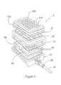
- FIGS. 1 to 3 illustrate a representative embodiment of a plate liner 12, each well-suited for controlling pendant drop formation in the broad class of microarrays that comprise -- in general -- an array of wells 310 in a sample plate 300 and an array of underdrains 150.
- the plate liner 12 is designed to engage detachably onto said specific pre-defined microarray, such that the force required to manually disengage the plate liner 12 from said specific pre-defined microarray is substantially less than the force required to separate the wells from the underdrains 150.
- the plate liner 12 comprises an array of hermetic spout isolators 16 that will align or otherwise register well with the underdrains 150 when the plate liner is engaged.
- the close and structurally- appropriate conformity with which the plate liner 12 registers and engages the microarray is central to the invention's control of pendant drop formation. Fluid samples placed in wells 310 and passing into the underdrains 150 are hermetically blocked from flowing past the hermetic spout isolators 16.
- the plate liner 12 is pre-configured to "detachably engage" a microarray by means of two basic alternative approaches.
- the plate liner 12 is engineered to "engage detachably" by means of a friction-fitted coupling of the hermetic spout isolators 16 with underdrain spouts 10. Examples of such "detachable engagement" are illustrated in Figures 1 and 3 .
- the hermetic spout isolators 16 follow closely the contours of the underdrain spouts 10, with the plate liner 12 facing flush against the underdrain plate 150.
- the hermetic spout isolators 16 also follow closely the contours of the underdrain spouts 10, but also conform to accommodate the presence of protective circular collars 140 that protrude from the planar underdrain support 150.
- the plate liner 12 is engineered such that it “engages detachably” by means of one or more friction-fitted, peripheral edge couplings 14 of the plate liner 12 onto the microarray.
- the spout isolators in micro-receptacle form 16 are intended to capture only the substantially smaller volumes of fluid that drip incidentally out of the samples wells 310 through the spouts 10 during, for example, long sample incubation steps.
- each spout isolator in micro-receptacle form 16 will generally be "substantially less" than the volume of each sample well 310, if not "negligible" ( i . e ., approximately .025 ml to approximately .125 ml).
- Such small volume receptacles result in a relatively low profile plate liner 12 that can be engaged inconspicuously and/or unobtrusively onto a microarray, thereby promoting broader microarray stackability and mechanical compatibility with legacy and/or extant array handling, incubation, and sensing devices and hardware.
- the means should be constructed such that the force required to manually disengage the plate liner 12 from said drain plate 150 is substantially less than the force required to disengage or otherwise separate said drain plate 150 from said sample plate 300.
- the force should be sufficient to "hold” the plate liner 12 securely in place, forming good water-tight seals, across a reasonably broad range of handling conditions.
- ease of detachment is particularly important.
- the force required to disengage the plate liner 12 should still be kept relatively low to promote and/or facilitate gentle, non-disruptive manual disengagement.
- the principal functionality of the hermetic spout isolators 16 is to either (a) prevent the formation of pendant drops altogether or (b) contain pendant drops that do form. "Prevention" is best accomplished by a hermetic spout isolator 16 that closely conforms and engages with an underdrain spout 10 such that the aperture of said spout 10 is sealed by the isolator 16, as illustrated by the embodiment of Figure 1 .
- a hermetic spout isolator 16 formed as a micro-receptacle that is capable of hermetically capturing fluid drops expressed out of said spouts 10 in a volume substantially less than the volume of said wells 310.
- Creating an air-tight hermetic seal outside and proximate the spout 10 can also prevent liquid from dripping into the spout isolators in micro-receptacle form because air trapped therein cannot be displaced.
- hermetic spout isolator 16 In configuring the hermetic spout isolator 16, it is desirable to consider pendant drop theory and the maximum volumes that a spout of a given size and material can sustain. For example, a hermetic spout isolating micro-receptacle 16 should be deep enough to prevent drops of a certain size from contacting the plate liner and "touching off". Such contact has been shown to initiate flow from the device and can potentially drain the well of liquid. Certain spout sizes are capable of sustaining drops up to 20 microliters with heights of .100". A "" spout isolating micro-receptacle 16 would need to be at least .100" tall to prevent "touch off'.
- the flow of fluid through a spout 10 is hermetically isolated by a physical water-tight seal that forms at or around the spout 10 when the plate liner 12 is detachably engaged onto the microarray.
- a physical water-tight seal that forms at or around the spout 10 when the plate liner 12 is detachably engaged onto the microarray.
- Plate liner 12 is preferably cast, molded, or otherwise formed from polymeric material, such as thermoplastics and/or thermosets.
- the polymeric material should have high structural resolution, so that it is capable of forming thin wall structures, thereby reducing the liner's overall bulk.
- certain other factors that may be considered include, for example, rigidity and elasticity; structural and thermal durability; weight; and cost. Rigidity and elasticity will influence, among other things, the "detachable engageability" of plate liner 12, as well as its ability to form good hermetic seals at or proximate the underdrain spouts 10.
- Structural and thermal durability promotes better resistance to the mechanical and thermal stresses often encountered, for example, during automated mechanical handling, autoclaving, steam sterilization, and the like. Weight to some extent will influence “detachable engageability”. Lighter weight materials are preferred because they are less prone to premature detachment during vigorous handling. Finally, because microarrays are generally "single-use" items, the material and manufacturing costs of a plate liner 12 should coincide well with its likely disposability.
- suitable polymeric material include, but are not limited to, polycarbonates, polyesters, nylons, PTFE resins and other fluoropolymers, acrylic and methacrylic resins and copolymers, polysulphones, polyethersulphones, polyaryl-sulphones, polystyrenes, polyvinyl chlorides, chlorinated polyvinyl chlorides, ABS and its alloys and blends, polyurethanes, thermoset polymers, polyolefins ( e.g. , low density polyethylene, high density polyethylene, and ultrahigh molecular weight polyethylene and copolymers thereof), polypropylene and copolymers thereof, and metallocene generated polyolefins.
- Preferred polymers are polyolefins, in particular polyethylenes and their copolymers, polystyrenes, and polycarbonates.
- the plate liner 12 is, for certain applications, desirably formed (entirely or partially) of an elastomeric material capable of facilitating and/or promoting good seal formation.
- the elastomeric material is overmolded or otherwise deposited on a base thermoplastic or thermoset plate liner at or proximate the boundaries circumscribing each hermetic spout isolator 16.
- the hermetic spout isolators 16 of the plate liner 12 are formed as micro-receptacles that are particularly configured to enable automated optical interrogation of fluid captured therein.
- the use of light transmissive materials affords the possibility of forming or otherwise integrating optical elements and/or functionality into the design of the hermetic spout isolator 16.
- the floor of the hermetic spout isolator can be shaped in the form of, for example, a concave, convex, spherical, or cylindrical lens.
- An integrated optical element can assist, enable, and or facilitate the optical identification, monitoring, detection, or analysis of the hermetic spout isolator 16 and/or its fluid charge.
- Preferred optical polymers include, but are not limited to, styrene, styrene acrylonitrile, and acrylics.
- Optical attenuation can be achieved in said optical elements, for example, by the inclusion of pigments, dyes, fillers and other light absorbing materials.
- Common materials include carbon black, titanium dioxide and the like all of which are well known to one of ordinary skill in the industry.
- Figure 5 shows one such embodiment of an optically interrogatible plate liner 400.
- the areas of the plate liner 400 that are at least the bottom surfaces 402 of the spout isolators 404 are made of an optical polymer described above.
- the sidewalls 406 of the isolators 404 as well as the web area 408 between the isolators 404 are formed of an optically attenuating material such as a polymer containing a dye, pigment, filler or other light absorbing material.
- the issue of light crosstalk is limited only to the web area 408 and the sidewalls 406 may a desired be clear and may even optically transmissive if desired (not shown).
- Such plate liners can be made by a variety of techniques depending on the format desired and the material used. For example one can co-mold two plastics, one of which contains the optically attenuating material for at least the web area and optionally the sidewalls as well.
- the liner can be made of an optically transmissive polymer and the web area and optionally the sidewalls can then be coated with the optically attenuating material of choice.
- Other methods of forming the device according to this embodiment can be used as well and would be well known to one of ordinary skill in the art.
- the present invention provides a kit that includes pre-selected compatible components suited for the accomplishment of said protocols.
- the kit by design targets pre-selected modes of practicing the invention, the inclusion of pre-selected compatible components promotes ease of use, consistency of results, and comparatively lower user costs.
- the microarray kit comprises, within sanitary packaging, a sample plate 300; a drain plate 150, and a plate liner 12, each of which are desirably "pre-sterilized”.
- the sample plate 300 and drain plate 150 comprise, respectively, an array of wells 310 and array of underdrains 10.
- the drain plate 150 is detachably engaged or engageable onto said sample plate 300 such that, when engaged, the array of underdrains 10 are sufficiently in register with said wells 310 to enable flow of fluid from said well 310 immediately into said underdrains without cross-contamination.
- the “matching”, plate liner 12 comprises an array of hermetic spout isolators 16, and is detachably engaged or engageable manually onto said drain plate 150.
- the hermetic spout isolators 16 When engaged, the hermetic spout isolators 16 are in register with said underdrains 10, such that (a) the flow of fluid placed in said wells 310 and passing into said underdrains 10 is hermetically blocked from flowing past the hermetic spout isolators 16; and (b) the force required to manually disengage the plate liner 12 from said drain plate 150 is substantially less than the force required to disengage said drain plate 150 from said sample plate 300.
- Pre-sterilization of the component parts of the inventive kit can be accomplished, for example, by steam sterilization, photo- irradiation, and/or by chemical treatment.
- each component part can be individually and sanitarily packaged within a larger outer sanitary package.
- the plate liner 12 of the present invention can be provided as a "stand-alone" item, or -- more preferably -- as a pre-matched component of the aforementioned kit.
- the microarray device to which it engages will in general comprise an array of underdrains 10 and an array of sample wells 310. For purposes of illustration, representative examples of such microarray device are provided in Figures 1 to 3 .
- an underdrain -- having a monolithic construction -- is provided with certain structural features above and below (i . e ., upstream and downstream, respectively) a planar support 150. These structural features substantially encircle (or otherwise surround) a central funnel-shaped opening 142 that leads into and through the planar support 150.
- a tube-shaped spout 10 aligned co-axially with and below the funnel-shaped opening 142 and optionally -- as shown in Figure 3 - a protective circular collar 140 co-axially surrounding the tubular spout 10 with a plurality of spacers 152a and 152b formed between the lower surface of the planar support 150 and the outer wall of the protective circular collar 140.
- circular engaging means 130 for fixing a well to the underdrain, the circular engaging means being aligned co-axially with and above the funnel-shaped opening 142.
- the tubular spout 10, the funnel-shaped opening 142, and the circular engaging means 130 are all co-axial in Figures 1 to 3 , such alignment is not pivotal. An offset arrangement can be employed if desired.
- the underdrain spouts 10 of the drain plate 150 packaged within the inventive kit are desirably configured with straight side walls.
- the outer side wall of spout 10 should run substantially parallel to the spout's central axis, wherein said central axis generally corresponds to the flow path through the spout 10.
- the outer side wall(s) of spout 10 configured as such will likely also be substantially parallel to the direction in which fluid is expressed out of the spout 10 into a receiving element. This -- it is felt -- provides distinct advantage.
- the length of said wall should be fairly substantial. While it is not required that the entire length of the outer side surface of spout 10 be straight, little advantage is offered where the straight side walls occupies, for example, only the rim of the spout. While there is no particular absolute "cut off' in respect of length, it is envisaged that in most circumstances, the outer side surface will run substantially parallel to said central axis of the spout ( i . e ., "straight") from its furthest downstream end to at least a point corresponding to midway the spout 10's fluid pathway.
- a further impediment to pendant drop up-crawl is provided by the roughly textured outer side and end surfaces of the spout 10.
- the spout may likely be already made of (or coated with) a polymeric material that inherently possesses some measure of hydrophobicity.
- a roughly textured outer surface which in accordance with the present invention comprises a coarse microstructure of cracks, crevices, pits, ridges, bumps, and/or like peaks and valleys -- can enhance this inherent hydrophobicity, by disrupting, reducing, and/or rendering more tortuous the surface area(s) upon which a drop of aqueous fluid could otherwise "crawl" (for example, by capillary action).
- hydrophilicization repeatable and consistent empirical data were collected validating the positive effect of a roughened spout surface on pendant drop formation.
- the coarse microstructure can be provided on the spout either during the forming of the underdrain (for example, by use of an appropriately roughly textured mold), or subsequently, by well-known mechanical and chemical surface roughening processes.
- Mechanical processes include, but are not limited to, embossing, etching, and treatment with abrasives.
- Chemical processes include, but are not limited to, treatment with caustic, acidic or other corrosive solutions, thermal and/or photodegradation, and laser ablation.
- Funnel-shaped opening 142 provides a gradual transition for fluid to flow from a comparatively more spacious well (e.g. , well 310) into the much more constricted fluid pathway of spout 10.
- the furthest downstream end of funnel-shaped opening 142 merges smoothly into fluid pathway of tubular spout 10, at which point the diameter of opening 142 is equal to that of fluid pathway.
- the diameter of the fluid pathway 18 should be sufficiently small, such that -- with the combined influence of the material surface properties of the underdrain -- fluid within funnel-shaped opening 142 (and hence, fluid within a filtration device) will not flow therethrough until a sufficient predetermined driving force (e.g. , vacuum pressure, positive pressure, centrifugal force, etc.) is attained.
- a sufficient predetermined driving force e.g. , vacuum pressure, positive pressure, centrifugal force, etc.
- the protective circular collar 140 serves a number of functions.
- the protective circular collar 140 serves as an alignment guide, which is useful in instances wherein underdrain is to be aligned with a downstream fluid receptacle.
- the protective circular collar 140 is formed to enable the nesting thereof within the corresponding, comparatively large volume, fluid collection receptacle 46 into which filtrate is to be transferred downstream. Lateral movement of the fluid collection receptacle is repressed by the protective circular collar which is generally tightly seated within said receptacle 46.
- the protective circular collar 140 serves also to minimize any contamination between wells and/or surrounding areas by guarding against aerosols or the splashing of the liquid filtrate as it is dispensed through the spout 10.
- the protective circular collar 140 can be constructed such that it protrudes from planar support 150 to an extent further than the tubular spout 10, thus offering some measure of physical protection to the tubular spout 10 from damage that may be encountered during assembly, use, or possible disassembly of a filtration device.
- Spacers 152a and 152b are block-like structures that radiate outwardly from the outer wall of the protective circular collar 140. In addition to providing some lateral support to the protective circular collar 140, spacers 152a and 152b also prevent a lower corresponding fluid collection receptacle 46 from pressing completely up against planar support 150, and creating an air tight seal that would prevent or otherwise frustrate the evacuation of a fluid though the filtration device 5. Provision of intermittently positioned spacers provides air gaps, enabling the displacement of air throughout the device, as is needed, for example, in both vacuum- and centrifugally-driven filtration.
- Well engaging means 130 on the upstream side of the planar support 150 is configured as an annular seat into which a well can be pushed into, in a manner comparable to the aforementioned relationship between the protective circular collar 140 and the fluid receptacle 46.
- a well 310 is typically fixed within annular well-engaging means 150 by friction.
- annular well engaging means 130 "fits" around the well 310's bottom end, rather than the well 310 fitting around the well engaging means 130.
- the permanency of the fixation of a well 310 onto the underdrain 100 by said well engaging means 130 depends on intended use.
- advantage is realized by engineering the well-engaging means 150 such that the fixation of a well therewith is "sufficiently tight” to enable “clean” clinically-acceptable filtration, yet “sufficiently loose” to enable a relatively non-destructive disassembly of the resultant filtration device.
- Such disassembly can provide a practitioner additional avenues (not otherwise available) for observing, testing, or otherwise inspecting the separation material (e.g. , a membrane) interposed between the mated well and underdrain. Such inspection often yields meaningful information.
- Each well 310 of the plate 300 is preferably matched in a 1:1 ratio to each underdrain in the underdrain plate. Separation material is provided between the plates, for example, in the form of several individual membranes 200 discretely interposed between each coupled well/underdrain pair.
- the microarray filtration device comprises a plate-like array of wells and a corresponding plate-like array of underdrains
- the underdrains need not in all instances be provided collectively in one component.
- a filtration device is contemplated wherein discrete underdrains are individually “press fitted" onto the bottom end of the plate's wells.
- multiwell plates can be made in formats containing 6-wells, 96-wells, 384-wells, or up to 1536-wells and above.
- the number of wells used is not critical to the invention.
- the wells are typically arranged in mutually perpendicular rows. For example, a 96 well plate will have 8 rows of 12 wells. Each of the 8 rows is parallel and spaced apart from each other. Likewise, each of the 12 wells in a row is spaced apart from each other and is in parallel with the wells in the adjacent rows.
- a plate containing 1536 wells typically has 128 rows of 192 wells.
- the separation material 200 is placed substantially between the well(s) and the underdrain(s), such that fluid placed in a well is flowable first into and through the separation material 200, then into and ultimately out of the underdrain.
- the separation material can be any material specifically engineered for, and thus, capable of isolating, screening, binding, removing, or otherwise separating a predetermined target (e.g. , viruses, proteins, bacteria, particulate matter, charged or otherwise labeled compounds, biochemical fragments, etc.) from a fluid stream passing therethrough.
- a predetermined target e.g. , viruses, proteins, bacteria, particulate matter, charged or otherwise labeled compounds, biochemical fragments, etc.
- the determinants of separation can be based, for example, on the size, weight, surface affinities, chemical properties, and/or electrical properties of the predetermined target.
- the separation material is preferably located at or close to the bottom of the well. Such placement -- it is felt -- can reduce incidence of so-called "vapor locking" that can occur when a well is repetitively filled and vacuum filtered.
- the preferred separation material is a filtration membrane.
- the filtration membrane can be bonded to the well (or the underdrain) or can be held in position by being compressed between the well and the underdrain. Any bonding method can be utilized.
- Representative suitable membranes are the so-called "microporous" type made from, for example, nitrocellulose, cellulose acetate, polycarbonate, and polyvinylidene fluoride.
- the membranes can comprise an ultrafiltration membrane, which membranes are useful for retaining objects as small as about 100 daltons and as large as about 2,000,000 daltons. Examples of such ultrafiltration membranes include polysulfone, polyvinylidene fluoride, cellulose, and the like.
- separation materials include, depth filter media (such as those made from cellulosic or glass fibers), loose or matrix-embedded chromatographic beads, frits and other porous partially-fused vitreous substance, electrophoretic gels, etc.
- depth filter media such as those made from cellulosic or glass fibers
- chromatographic beads such as those made from cellulosic or glass fibers
- frits such as those made from cellulosic or glass fibers
- frits such as those made from cellulosic or glass fibers
- porous partially-fused vitreous substance such as electrophoretic gels, etc.
- electrophoretic gels etc.
- These separation materials -- as well as membranes -- can further comprise or be coated with or otherwise include filter aids and like additives, or other materials, which amplify, reduced, change, or otherwise modify the separation characteristics and qualities of the base underlying material, such as for example the grafting of target specific binding sites onto a chromatographic bead.
- the separation material When incorporated into a microarray filtration device, the separation material can be interposed between the paired wells and underdrains either "expansively" (e.g. , using one membrane sheet to cover all pairs) or “discretely” (e.g. ., using separate and discrete membranes for each pair).
- the separation material is interposed expansively, care should be taken to minimize or otherwise frustrate fluid "cross-talk" between the pairs that can occur as fluid spreads laterally through the separation material, such as by using the well-known separations materials that are constructed specifically to contain (as in zones), mitigate, frustrate, or prevent lateral cross-flow.
- a filter sheet By means of other cutting techniques, such as laser cutting, cutting by means of water jets, or by providing sharp edges circumscribing the bottom opening of the wells or circumscribing the upper opening of the underdrain.
- an appropriately-sized, well-fitting discrete filter element can be simultaneously punched out and appropriately positioned in each well/underdrain pair by placing an expansive sheet between the array of wells and the array of underdrains, and then pressing them tightly together.
- the sheet in this regard can be initially bonded or secured to the array of wells, or the array of underdrains, or neither ( i . e ., loose).
- a monolithic microarray filtration device is contemplated wherein the wells and underdrains thereof are not formed separately. Rather, each well in said monolithic microarray filtration device is provided with an underdrain that is formed continuously therewith. Separation material is installed within the device, for example, in the same manufacturing step (or steps) in which the underdrain-bearing well is formed, and such that, in the resultant monolithic microarray filtration device, the flow path of fluid therethrough will be essentially the same as the flow path provided by a two-piece construction.
- the detachably engageable plate liner 12 can engage onto either the underdrain spouts or onto a peripheral edge of the monolithic construction.
- the monolithic microarray filtration device cannot be easily separated like the two-piece construction for inspection and analysis of enclosed separation material, it tends to be more structurally robust, and is better suited for robotic handling, and is less likely to leak, and is less vulnerable to interwell cross-talk.
- microarray filtration device 5 is drained typically (though not necessarily) by drawing a vacuum through the device 5 such the fluid sample in each well 310 flows into and out of each respective underdrain 100 through separation material 200.
- FIG 4 An example of a vacuum manifold assembly suitable for such the conduct of such process is shown in Figure 4 .
- the vacuum manifold assembly of Figure 4 comprises a base 37, which acts as a vacuum chamber and contains hose barb 65 for connection to an external vacuum source through hose 67.
- liquid collection means such as either a collection tray 44 and/or a receiving plate 42 having a plurality of receptacles 46 for collecting fluid flowing out of each corresponding underdrain.
- the individual chambers 46 are associated each with a single well 310 in the well array 300 of the microarray filtration device 5.
- a microarray support 36 holding the microarray filtration device 5 above the fluid collection means is separated by gaskets 32 and 34 which form an airtight seal in the presence of a vacuum.
Landscapes
- Health & Medical Sciences (AREA)
- Chemical & Material Sciences (AREA)
- Analytical Chemistry (AREA)
- General Health & Medical Sciences (AREA)
- Hematology (AREA)
- Clinical Laboratory Science (AREA)
- Chemical Kinetics & Catalysis (AREA)
- Automatic Analysis And Handling Materials Therefor (AREA)
- Sampling And Sample Adjustment (AREA)
- Filtering Materials (AREA)
- Investigating Or Analysing Biological Materials (AREA)
Applications Claiming Priority (3)
| Application Number | Priority Date | Filing Date | Title |
|---|---|---|---|
| US58263604P | 2004-06-24 | 2004-06-24 | |
| US67647205P | 2005-04-29 | 2005-04-29 | |
| EP05105544A EP1611956A3 (fr) | 2004-06-24 | 2005-06-22 | Plaque détachable pour protéger le drainage d'un appareil d'essai multipuits |
Related Parent Applications (1)
| Application Number | Title | Priority Date | Filing Date |
|---|---|---|---|
| EP05105544.0 Division | 2005-06-22 |
Publications (2)
| Publication Number | Publication Date |
|---|---|
| EP2258480A2 true EP2258480A2 (fr) | 2010-12-08 |
| EP2258480A3 EP2258480A3 (fr) | 2011-03-30 |
Family
ID=35005812
Family Applications (2)
| Application Number | Title | Priority Date | Filing Date |
|---|---|---|---|
| EP10178410A Withdrawn EP2258480A3 (fr) | 2004-06-24 | 2005-06-22 | Plaque détachable pour protéger le drainage d'un appareil d'essai multipuits |
| EP05105544A Withdrawn EP1611956A3 (fr) | 2004-06-24 | 2005-06-22 | Plaque détachable pour protéger le drainage d'un appareil d'essai multipuits |
Family Applications After (1)
| Application Number | Title | Priority Date | Filing Date |
|---|---|---|---|
| EP05105544A Withdrawn EP1611956A3 (fr) | 2004-06-24 | 2005-06-22 | Plaque détachable pour protéger le drainage d'un appareil d'essai multipuits |
Country Status (2)
| Country | Link |
|---|---|
| US (1) | US7618592B2 (fr) |
| EP (2) | EP2258480A3 (fr) |
Families Citing this family (7)
| Publication number | Priority date | Publication date | Assignee | Title |
|---|---|---|---|---|
| US6117394A (en) * | 1996-04-10 | 2000-09-12 | Smith; James C. | Membrane filtered pipette tip |
| GB0521117D0 (en) * | 2005-10-18 | 2005-11-23 | Amersham Biosciences Ab | Multiwell plate |
| FR2897783B1 (fr) * | 2006-02-24 | 2008-05-30 | Millipore Corp | Dispositif pour le controle microbiologique, ensembles de controle et d'incubation le comportant et procede le mettant en oeuvre |
| USD623300S1 (en) | 2009-01-30 | 2010-09-07 | Edge Biosystems | Filterplate |
| WO2011005801A1 (fr) * | 2009-07-08 | 2011-01-13 | Speware Corporation | Elément de scellement luer pour colonnes d'extraction en phase solide |
| US10119112B2 (en) * | 2010-03-02 | 2018-11-06 | Universite Technologie de Compiegne—UTC | Multi-reactor unit for dynamic cell culture |
| US11504716B2 (en) | 2020-06-05 | 2022-11-22 | Pall Corporation | Multiwell device and method of use |
Citations (13)
| Publication number | Priority date | Publication date | Assignee | Title |
|---|---|---|---|---|
| US4902481A (en) | 1987-12-11 | 1990-02-20 | Millipore Corporation | Multi-well filtration test apparatus |
| US4948564A (en) | 1986-10-28 | 1990-08-14 | Costar Corporation | Multi-well filter strip and composite assemblies |
| US5108704A (en) | 1988-09-16 | 1992-04-28 | W. R. Grace & Co.-Conn. | Microfiltration apparatus with radially spaced nozzles |
| US5141719A (en) | 1990-07-18 | 1992-08-25 | Bio-Rad Laboratories, Inc. | Multi-sample filtration plate assembly |
| US5264184A (en) | 1991-03-19 | 1993-11-23 | Minnesota Mining And Manufacturing Company | Device and a method for separating liquid samples |
| US6159368A (en) | 1998-10-29 | 2000-12-12 | The Perkin-Elmer Corporation | Multi-well microfiltration apparatus |
| WO2001045844A1 (fr) | 1999-12-23 | 2001-06-28 | 3M Innovative Properties Company | Plaque a microtitration et procede de fabrication associe |
| WO2001051206A1 (fr) | 1999-12-23 | 2001-07-19 | 3M Innovative Properties Company | Plaque microtitre a elements filtrants et procede de fabrication associe |
| US6391241B1 (en) | 1997-06-06 | 2002-05-21 | Corning Incorporated | Method of manufacture for a multiwell plate and/or filter plate |
| US6419827B1 (en) | 1998-10-29 | 2002-07-16 | Applera Corporation | Purification apparatus and method |
| US20020155034A1 (en) | 1999-12-23 | 2002-10-24 | 3M Innovative Properties Company | Well-less filtration device |
| WO2002096563A2 (fr) | 2001-05-31 | 2002-12-05 | Pall Corporation | Puits servant a traiter un fluide |
| US20020195386A1 (en) | 2001-06-25 | 2002-12-26 | Young Stephen G. | Filtration and separation apparatus and method of assembly |
Family Cites Families (7)
| Publication number | Priority date | Publication date | Assignee | Title |
|---|---|---|---|---|
| US4895706A (en) | 1986-10-28 | 1990-01-23 | Costar Corporation | Multi-well filter strip and composite assemblies |
| US5342581A (en) * | 1993-04-19 | 1994-08-30 | Sanadi Ashok R | Apparatus for preventing cross-contamination of multi-well test plates |
| US6517781B1 (en) * | 1997-06-02 | 2003-02-11 | Aurora Biosciences Corporation | Low fluorescence assay platforms and related methods for drug discovery |
| US20030226796A1 (en) * | 2002-06-11 | 2003-12-11 | 3M Innovative Properties Company | Modular system for separating components of a liquid sample |
| CA2467131C (fr) | 2003-05-13 | 2013-12-10 | Becton, Dickinson & Company | Appareil et methode de traitement d'echantillons biologiques et chimiques |
| US7063216B2 (en) * | 2003-09-04 | 2006-06-20 | Millipore Corporation | Underdrain useful in the construction of a filtration device |
| US8753588B2 (en) | 2003-10-15 | 2014-06-17 | Emd Millipore Corporation | Support and stand-off ribs for underdrain for multi-well device |
-
2005
- 2005-06-01 US US11/142,542 patent/US7618592B2/en not_active Expired - Fee Related
- 2005-06-22 EP EP10178410A patent/EP2258480A3/fr not_active Withdrawn
- 2005-06-22 EP EP05105544A patent/EP1611956A3/fr not_active Withdrawn
Patent Citations (16)
| Publication number | Priority date | Publication date | Assignee | Title |
|---|---|---|---|---|
| US4948564A (en) | 1986-10-28 | 1990-08-14 | Costar Corporation | Multi-well filter strip and composite assemblies |
| US4902481A (en) | 1987-12-11 | 1990-02-20 | Millipore Corporation | Multi-well filtration test apparatus |
| US5108704A (en) | 1988-09-16 | 1992-04-28 | W. R. Grace & Co.-Conn. | Microfiltration apparatus with radially spaced nozzles |
| US5141719A (en) | 1990-07-18 | 1992-08-25 | Bio-Rad Laboratories, Inc. | Multi-sample filtration plate assembly |
| US5264184A (en) | 1991-03-19 | 1993-11-23 | Minnesota Mining And Manufacturing Company | Device and a method for separating liquid samples |
| US5464541A (en) | 1991-03-19 | 1995-11-07 | Minnesota Mining And Manufacturing Company | Device and a method for separating liquid samples |
| US20020104795A1 (en) | 1997-06-06 | 2002-08-08 | Cote Richard Alexander | Multiwell filter and/or plate |
| US6391241B1 (en) | 1997-06-06 | 2002-05-21 | Corning Incorporated | Method of manufacture for a multiwell plate and/or filter plate |
| US6338802B1 (en) | 1998-10-29 | 2002-01-15 | Pe Corporation (Ny) | Multi-well microfiltration apparatus |
| US6419827B1 (en) | 1998-10-29 | 2002-07-16 | Applera Corporation | Purification apparatus and method |
| US6159368A (en) | 1998-10-29 | 2000-12-12 | The Perkin-Elmer Corporation | Multi-well microfiltration apparatus |
| WO2001045844A1 (fr) | 1999-12-23 | 2001-06-28 | 3M Innovative Properties Company | Plaque a microtitration et procede de fabrication associe |
| WO2001051206A1 (fr) | 1999-12-23 | 2001-07-19 | 3M Innovative Properties Company | Plaque microtitre a elements filtrants et procede de fabrication associe |
| US20020155034A1 (en) | 1999-12-23 | 2002-10-24 | 3M Innovative Properties Company | Well-less filtration device |
| WO2002096563A2 (fr) | 2001-05-31 | 2002-12-05 | Pall Corporation | Puits servant a traiter un fluide |
| US20020195386A1 (en) | 2001-06-25 | 2002-12-26 | Young Stephen G. | Filtration and separation apparatus and method of assembly |
Also Published As
| Publication number | Publication date |
|---|---|
| EP2258480A3 (fr) | 2011-03-30 |
| EP1611956A2 (fr) | 2006-01-04 |
| US20050287046A1 (en) | 2005-12-29 |
| EP1611956A3 (fr) | 2006-06-07 |
| US7618592B2 (en) | 2009-11-17 |
Similar Documents
| Publication | Publication Date | Title |
|---|---|---|
| EP0403679B1 (fr) | Dispositif d'essai de filtration à godets multiples | |
| US5116496A (en) | Membrane-containing wells for microtitration and microfiltration | |
| JP3899049B2 (ja) | マイクロプレートを保護するトレー用の裏蓋 | |
| KR100923482B1 (ko) | 유체처리용 웰 | |
| US7413910B2 (en) | Multi-well apparatus | |
| US8007743B2 (en) | Multifunctional vacuum manifold | |
| JPH02187110A (ja) | マイクロフィルトレーション装置とその方法 | |
| JP2002511931A (ja) | フィルタプレート | |
| US7063216B2 (en) | Underdrain useful in the construction of a filtration device | |
| JP2011092937A (ja) | マルチウェルデバイス用の下部排液装置のための支持体およびスタンドオフリブ | |
| JPWO2007123100A1 (ja) | フィルター付きマイクロプレート | |
| US7618592B2 (en) | Detachable engageable microarray plate liner | |
| JP4794582B2 (ja) | 多機能真空マニフォールド | |
| US6896144B2 (en) | Filtration and separation apparatus and method of assembly | |
| US20030226796A1 (en) | Modular system for separating components of a liquid sample | |
| CN110869102B (zh) | 具有可变压缩密封件的多孔板 | |
| US20240116051A1 (en) | Device and Method for Separating Blood Plasma from Whole Blood | |
| EP3416737A1 (fr) | Contenant pour un ensemble de filtration | |
| AU2002247290A1 (en) | Multi-well apparatus |
Legal Events
| Date | Code | Title | Description |
|---|---|---|---|
| PUAI | Public reference made under article 153(3) epc to a published international application that has entered the european phase |
Free format text: ORIGINAL CODE: 0009012 |
|
| 17P | Request for examination filed |
Effective date: 20100922 |
|
| AC | Divisional application: reference to earlier application |
Ref document number: 1611956 Country of ref document: EP Kind code of ref document: P |
|
| AK | Designated contracting states |
Kind code of ref document: A2 Designated state(s): DE FR GB |
|
| PUAL | Search report despatched |
Free format text: ORIGINAL CODE: 0009013 |
|
| AK | Designated contracting states |
Kind code of ref document: A3 Designated state(s): DE FR GB |
|
| RAP1 | Party data changed (applicant data changed or rights of an application transferred) |
Owner name: EMD MILLIPORE CORPORATION |
|
| STAA | Information on the status of an ep patent application or granted ep patent |
Free format text: STATUS: THE APPLICATION IS DEEMED TO BE WITHDRAWN |
|
| 18D | Application deemed to be withdrawn |
Effective date: 20130103 |