EP2258518A2 - Appareil adaptable à cartouche de vis - Google Patents
Appareil adaptable à cartouche de vis Download PDFInfo
- Publication number
- EP2258518A2 EP2258518A2 EP10003233A EP10003233A EP2258518A2 EP 2258518 A2 EP2258518 A2 EP 2258518A2 EP 10003233 A EP10003233 A EP 10003233A EP 10003233 A EP10003233 A EP 10003233A EP 2258518 A2 EP2258518 A2 EP 2258518A2
- Authority
- EP
- European Patent Office
- Prior art keywords
- conveyor
- carriage
- screw magazine
- screw
- guide
- Prior art date
- Legal status (The legal status is an assumption and is not a legal conclusion. Google has not performed a legal analysis and makes no representation as to the accuracy of the status listed.)
- Granted
Links
Images



Classifications
-
- B—PERFORMING OPERATIONS; TRANSPORTING
- B25—HAND TOOLS; PORTABLE POWER-DRIVEN TOOLS; MANIPULATORS
- B25B—TOOLS OR BENCH DEVICES NOT OTHERWISE PROVIDED FOR, FOR FASTENING, CONNECTING, DISENGAGING, OR HOLDING
- B25B23/00—Details of, or accessories for, spanners, wrenches, screwdrivers
- B25B23/02—Arrangements for handling screws or nuts
- B25B23/04—Arrangements for handling screws or nuts for feeding screws or nuts
- B25B23/045—Arrangements for handling screws or nuts for feeding screws or nuts using disposable strips or discs carrying the screws or nuts
Definitions
- the invention relates to a screw magazine attachment for a motor-driven screwdriver for screwing in screws, with a coupled by means of a coupling device to the screwdriver base and a tool guide for guiding a drivable by the screwdriver tool, with a supportable against a workpiece, along a carriage Displacement axis slidably guided on a carriage guide of the body guided carriage on which a magazine guide for guiding a strip-shaped, the screws providing screw magazine is arranged, wherein on the carriage for advancing the screw magazine a conveyor with a conveyor pawl part is arranged, which cooperates by a cooperating with the main body feed gear engages in a displacement stroke of the carriage relative to the base body in the screw magazine and this promotes.
- screw magazine attachments are well known in the field of hand tool machines in the meantime.
- the screw magazine is pre-conveyed by means of a pawl, so that after screwing a first screw a second, sequentially arranged after this in the screw magazine screw gets into the front of the screwdriver tool. Then, in a next displacement stroke of the carriage, the screwdriver tool again in engagement with the screw and screw them into a base. The carriage is supported on the ground.
- a basic idea of the invention is that the conveyor pawl part expediently performs a kind of oscillating movement between the engagement position and the release position.
- the pawl pivot axis or pendulum axis runs transversely, preferably at right angles, to the carriage displacement axis. This makes it possible, for example, that the conveyor pawl part at several points, preferably two places, engages in the screw magazine, if it promotes this. This effectively prevents jamming or distortion of the screw magazine in the magazine guide.
- the conveyor pawl part for example, not laterally pivots away from the carriage, for which, for example, a corresponding space must be provided laterally next to the carriage on the body or a free space for Ausschwenkamba.
- the conveyor pawl part for example swings inside the carriage.
- the arrangement according to the invention allows the conveying angle part that this can be conveniently pivoted from the engagement position to the release position, so that an operator can move the screw magazine. Namely, the conveyor is then advantageously completely free the screw magazine.
- the main body is expediently coupled fixedly with the screwdriver.
- a screw magazine guide for the screw magazine is arranged on the base body, so that the screw magazine is guided both on the guide of the main body and on the magazine guide of the carriage.
- the conveyor pawl part could be designed in the manner of a pinion.
- an embodiment in which the conveyor pawl part is designed as a latch lever or comprises a latch lever is preferred.
- the conveyor pawl expediently has at least two or exactly two engagement projections for simultaneous engagement in the screw magazine, expediently on mutually opposite sides of a respective screw to be conveyed.
- the engagement projections are expediently arranged parallel to the pawl pivot axis.
- the engagement projections are advantageously designed like a fork.
- the conveyor pawl part is spring-loaded in the engagement position by a spring arrangement.
- the spring arrangement comprises, for example, a spiral spring made of metal.
- the conveyor pawl part can also be pivoted by the conveyor gear of the attachment from the engagement position to the release position and / or vice versa, even if this is not the case in the embodiment.
- the spring-loaded variant has the advantage that the conveyor pawl part engages due to the load of the spring assembly in the screw magazine, if the conveyor pawl part facing an engagement receiving the screw magazine.
- At least one engagement projection, suitably all engagement projections, of the screw magazine attachment for engagement in the screw magazine and a support stop for supporting the spring arrangement are expediently arranged on opposite sides of the conveyor latch member. It is understood that the one or more engagement projections may also be loaded directly by the spring arrangement, which is not realized in the embodiment.
- the conveyor pawl part expediently has at least one operating handle for manual actuation between the engagement position and the release position.
- the conveyor pawl member has a T-shaped configuration, opposite side arms forming at least one engagement projection and a support stop for the spring arrangement, while an arm disposed between the side arms comprises or forms the operating handle.
- a manual operating handle is possible, for example, on a side facing away from the engagement projection side of the conveyor latch part.
- the conveyor pawl part may be integral, but also in another embodiment a plurality Components may have.
- the or the engagement projections made of metal while other component areas, such as the operating handle, are mechanically less loaded and are therefore advantageously made of plastic.
- the pawl pivot axis preferably forms an axis of rotation of a rotary part of the conveyor gear.
- the rotary part is for example at least one gear, at least one roller or the like.
- the conveyor pawl part is preferably mounted pivotably on a rotary axle which rotatably supports the rotary part.
- the conveyor pawl part can pivot about the Drehachs Published by the Machine pawl part.
- the Drehachs Supreme may be a rotation axis in the preferred embodiment of the invention, at the longitudinal end of each of which a rotary member, in particular a roller or a gear, is fixed or rotatable.
- the conveyor pawl part is expediently arranged on a sleeve penetrated by the rotary axis piece and rotatable relative to the rotary axis piece.
- the conveyor pawl member is preferably rotatably arranged, wherein a fixed arrangement of this sleeve is also possible.
- the sleeve preferably extends between the two aforementioned rotary parts, for example, the rollers or unrealized in the embodiment gears.
- the conveyor pawl part is preferably arranged in a receptacle, for example a receiving chamber, of the carriage.
- This receptacle is expediently closable by means of a closure part.
- the closure part is operated without tools in a preferred variant. This facilitates a tool-free disassembly of the screw magazine attachment, for example, for maintenance and / or if a component has jammed.
- the main body and / or the carriage expediently each have a housing.
- the aforementioned receiving chamber may be arranged for the conveyor latch part. It is understood that alternatively a frame-like configuration of both the carriage and the base body are possible in principle.
- the closure part for the receptacle or the receiving chamber expediently forms an abutment for the spring arrangement or comprises such an abutment.
- the spring tension can be canceled directly by removing the closure part, which facilitates disassembly.
- the bearing assembly stores the conveyor pawl expediently not only pivotable, but also displaceable. This can be realized for example by means of one or more slots.
- the one or more elongated holes may, as in the exemplary embodiment, have a straight course, but also a curved course or section. Thus, therefore, with the help of the elongated hole, a movement path of the conveyor latch part relative to the carriage can be specified.
- the bearing arrangement for mounting the conveyor pawl part is expediently open on one side and can be closed by means of a closure part.
- the bearing assembly for example, receives the Drehachs Fantasy. It is preferred if the bearing arrangement has at least one, preferably two laterally open slots.
- the conveyor pawl part is preferably arranged between the aforementioned oblong holes.
- the conveyor gear comprises a sliding gear and a slide track on the base body and a slide follower, for example a roller, roller or the like, is arranged on the carriage.
- a slide follower for example a roller, roller or the like
- the gate follower could for example be a slider.
- the slide follower or the slide followers are expediently turned parts, such as rollers, gears or the like.
- the link follower is rotatably mounted on a carriage in a preferred variant.
- the conveyor gear for example, the aforementioned slide track, the conveyor pawl part at a respective displacement stroke expediently before a high-low motion in which the conveyor pawl member is moved to the screw magazine in the direction of a next vorzu specialnde screw along.
- the slide track has an angular, suitably obliquely extending to the slide-displacement axis oblique section.
- the conveyor pawl part expediently slides along this high-depth movement, preferably against the force of a spring arrangement, particularly preferably the force of the spring assembly loading it in the direction of the screw magazine, until it can latch or latch into the next catch opening of the screw magazine.
- the screwdriver tool sets the screw magazine upon pivoting of the conveyor latch part from the engagement position into the release position and / or during the high-low movement of the conveyor latch part.
- the conveyor pawl part disengages from the screw magazine, without this continues to move.
- the screwdriver tool penetrates the screw magazine. But even then, when the screwdriver tool only penetrates into the head of the respective screw, it is set against a conveying movement.
- the conveyor gear is expediently designed so that the conveyor pawl part only determines the high-low motion when the screwdriver tool is in engagement with a screw and / or a screw magazine, that is, when the screwdriver tool sets the screw magazine against a conveying movement.
- the carriage is expediently spring-loaded in a screwing-in direction.
- the screw magazine attachment has a manually operable, in particular arranged on the carriage guide lock for holding the carriage in the carriage guide of the body.
- the guide lock can also be arranged on the base body.
- the guide lock spring-loaded in the locking position, alternatively, it would also be conceivable that the guide lock, for example, between a locking position and a release position can be latched.
- the carriage guide is expediently open at a side opposite the coupling device, which is advantageous for removing or receiving the carriage.
- the carriage expediently has at least two tool guides for the screwdriver tool.
- the guides may be, for example, laterally open guides, but are preferably guide eyes. This measure contributes to an optimal guidance of the screwdriver tool on the carriage.
- the magazine guide of the carriage expediently has an open at both ends, penetratable by the screws longitudinal slot.
- the screw magazine is freely movable in opposite directions and can be removed in any direction from the screw magazine attachment.
- a screw magazine attachment 10 may, as in FIG. 1 represented fixed on a screwing device 11 by means of a coupling device 12.
- the attachment 10 serves to provide and pre-promotion of screws 13 which are mounted on a strip-shaped screw magazine 14.
- the attachment 10 enables efficient and fast work, since it advances the screw magazine 14 by one position with a respective screwing of a screw 13, so that the next screw 13 is ready for screwing by means of the screwing 11.
- the screwdriver 11 is for example a cordless screwdriver or a network-connected screwdriver and can be easily grasped by the operator on an operating handle 15.
- the attachment 10 is arranged on a front side of the screwdriver 12.
- a rear side 16 of the attachment 10 is a Recording 17 on a receiving part 18 for a front end of the screwing device 11, namely a not visible in the drawing gear housing of the screwdriver 11 is provided.
- the receptacle 17 is a plug-in receptacle.
- a collar 19 of the coupling device 12 is accommodated on a main body housing 20 of a main body 21 of the attachment 10.
- a thread is present, in which a threaded portion of the receiving part 18 is screwed.
- the adjusting ring 19 is coupled for movement with an indicator part 22, which is arranged in a window 23 of the main body housing 20 and indicates the respective screw-in depth.
- the adjusting ring 19 is latching.
- a detent spring 24 engages in corresponding locking receptacles 93 on the adjusting ring 19 a.
- the main body housing 20 is constructed in two parts in the present case. Housing parts 25 are connected to each other by means of screws 26.
- the main body housing 20 has a gun-like shape. From a guide housing part 27 of the main body housing 20, which serves to guide a carriage 28, is a guide arm 29 with a main body magazine guide 30 for guiding the screw magazine 13 at an angle, in the present case approximately at right angles, from.
- the magazine guide 30 extends from the lower, free end of the guide arm 29 arcuately toward the carriage 28, which in turn also has a magazine guide 31 for guiding the screw magazine 14.
- the screws 13 are arranged successively or one behind the other.
- the screws 13 penetrate in a conventional manner, a band 32 of the screw magazine 14, wherein shanks 33 on the one hand project in front of the band 32 and on the other side of the belt 32, the heads 34 of the screws 13th issue.
- the screws 13 are screwed into a workpiece 35, their heads 34 penetrate the screw magazine belt 32.
- the two magazine guides 30, 31 each have a guide track 36, which has a longitudinal slot 37 on the front side.
- the screw magazine belt 32 is completely received in the guide track, that is, the two magazine guides 30, 31 engage over side edges 38 of the screw magazine belt 32, while the shafts 33 of the screws 13 longitudinal slots 37 of the two magazine guides 30, 31 penetrate.
- Both longitudinal slots 37 each extend from beginning to end of the magazine guide 30, 31, so that the screw magazine strip 32 equipped with the screws 13 can be pulled freely through the magazine guides 30, 31 not only in a conveying direction 39 but also in the opposite direction at least when a conveyor releases the screw magazine 14.
- the conveyor 40 is arranged substantially on the carriage 28.
- An essential component of the conveyor 40 is a conveyor pawl portion 41 which engages with engaging projections 42 in driving openings 43 on the side edges of the screw magazine belt 32 and thus the screw magazine 14 in the conveying direction 39 promotes ( FIGS. 4a-4e ).
- a slide guide 45 for guiding the carriage 28 is arranged in an inner space 44 of the main body housing 20, in particular of the guide housing part 27, a slide guide 45 for guiding the carriage 28 is arranged.
- the slide guide 45 comprises guide channels 46, which extend along a slide displacement axis 47 in the inner space 44.
- the carriage 28 is guided displaceably along the carriage displacement axis 47 on the base body 21.
- the stopper 49 has a U-shaped configuration. Side arms 50 of the stop 49 are guided longitudinally adjustable on stop guides 51 of the carriage 28, in this case of the carriage housing 48, so that an adaptation of the stopper 49 to a respective shaft length of a shaft 33 is possible.
- the stop 49 can be fixed by means of a holding device 52 in a respective longitudinal position.
- the holding device 52 comprises a locking part 53, the side arms project laterally in front of the carriage housing 48 in the region of the stop guides 51 and engage in locking receptacles 54 on the side arms 50.
- the locking member 53 can be manually pressed against the force of the locking member 54 in its locking position loading spring 55, so that the side arms of the locking member 53 out of engagement with the locking receptacles 54 and the workpiece stop 49 can be moved longitudinally.
- the side arms 50 of the workpiece stop 49 engage in the guide channels 46 and are guided in this along the carriage-displacement axis 47.
- the carriage 28 is guided linearly by means of the workpiece stop 49 on the main body 21.
- the carriage 28 is penetrated by a screwdriver tool 56 which extends parallel to the carriage-displacement axis 47 in the interior 44 of the base body 21.
- a rotary driving head of the screwdriver tool 56 is not visible in the drawing in the region of the coupling device 12 to be there rotatably coupled to the screwdriver 11.
- a shaft region 57 of the screwdriver tool 56 is guided on a tool guide 58 of the attachment 10, preferably on the one hand the coupling device 12 and on the other hand on Carriage 28.
- the screwdriver tool 56 penetrates the carriage 28, wherein a lateral guide along a carriage designed according to the invention is entirely conceivable.
- the carriage 28 When screwing in a screw 13, the carriage 28 is displaced against the force of a carriage 28 in the screwing direction loading slide spring 60 to the coupling device 12 back along the slide displacement axis 47 with respect to the base body 21.
- the slide spring 60 is supported on the one hand on the main body 21, for example on a rear wall in the region of the coupling device 12, and on the other hand on the carriage 28, for example in the region of a guide projection 61.
- the guide projection 61 penetrates into an interior of the present case designed as a helical spring spring 60 a.
- one of the two guide eyes 59 is arranged in the interior of the guide projection 61.
- the conveyor pawl part 41 is pivotable about a pawl pivot axis 62, which runs transversely, in the exemplary embodiment, at right angles to the carriage displacement axis 47.
- the pawl part 41 is mounted so as to be linearly displaceable both about the pawl pivot axis 62 and about a pawl sliding axis 63 relative to the carriage 28, in particular of the carriage housing 48.
- a type of carriage frame or slide body may be provided in an attachment according to the invention.
- the respective conveyor pawl part with respect to a carriage main body not only to the pawl pivot axis, but also to a latch axis on a respective Storage arrangement, for example in the manner of a bearing assembly 64 of the carriage 28, is mounted.
- the bearing arrangement 64 comprises bearing receptacles 65 on side walls 66 of the carriage housing 48.
- the two bearing receptacles 65 are configured in the form of oblong holes.
- the bearing receivers 65 are in the drawing downwards, that is open at a side facing away from the tool guide 58 side of the carriage 28, so that from there bearing parts of the conveyor latch part 41 can be inserted.
- bearing parts are presently formed by a sleeve 67 and a sleeve 67 penetrating Drehachs Georgia 68.
- the sleeve 67 is rotatably mounted on the conveyor pawl part 41 in a bearing receptacle 69.
- the Drehachs Indiana 68 in turn is rotatably received in the sleeve 67.
- the Drehachs Indiana 68 forms in this case a rotary shaft, at the respective ends rollers 70 are arranged.
- the rollers 70 are provided with tires 71, for example made of rubber, an elastic plastic or the like.
- the rollers 70 project laterally in front of the carriage housing 48.
- the sleeve 67 is received with their respective laterally projecting in front of the conveyor pawl portion 41 areas in the bearing seat 65 and can be linearly moved in this to the latch shaft 64.
- the conveyor pawl part 41 which can optionally also be fixedly arranged on the sleeve 67, can be pivoted about the pawl pivot axis 62 defined for the rotary axis piece 68.
- the conveyor pawl part 41 is received in a lockable by a closure member 73 receiving chamber 72 of the carriage 28.
- the side walls 66 bound the receiving chamber 72 laterally.
- the closure part 73 also closes the bearing arrangement 64, in particular the two bearing receptacles 65.
- a transverse width of the conveying pawl part 41 corresponds approximately to an inner spacing of the receiving chamber 72 in the region of the side walls 66.
- the closure member 73 also forms an abutment for a spring assembly 74 which loads the conveyor pawl member 41 in an engagement position E, in which the conveyor pawl member 41 engages the driving openings 43 of the screw magazine belt 32.
- the spring arrangement 74 comprises a spring 75, in the present case a helical spring, which is supported on the one hand on a support arm 76 of the conveyor latch part 41 and on the other hand on the inside of the closure part 73 facing the receiving chamber 72.
- a projection is arranged on the closure part 73, which penetrates into an inner space of the spring 75.
- the spring arrangement 74 also has a locking part 73 on the carriage housing 48 securing effect.
- guide projections and guide recesses are arranged with a course such that the spring 75 presses a guide projection or a plurality of guide projections against respective ends of one or more guide tracks.
- projections are arranged on the closure part 73, which engage in L-shaped, in the direction of the open side of the receiving chamber 73 ending receiving channels on the carriage housing 48.
- a projection or other support for the spring 75 is also provided on the conveyor pawl portion 41.
- the conveyor pawl member 41 can be manually adjusted from its engagement position E in a release position F, in which it does not engage in the driving openings 43 of the belt 32. Then, the band 32 can be pulled through the both sides open longitudinal slots 37 of the magazine guides 30, 31 even with screws 13 located on it.
- the conveyor pawl member 41 has an actuating arm 77 extending away from the support arm 76 and the Eingreifvorsprüngen 42 in the drawing down to a Insertion opening 78 for insertion of the conveyor pawl portion 41 extends into the receiving chamber 72 toward. There is then the free end of the actuating arm 77 actuated by an operator.
- the conveyor pawl part in side view, see for example FIG. 2a a substantially T-shaped shape.
- the bearing receiver 69 is arranged on the actuating arm 77 in the vicinity of the support arm 76.
- the conveyor pawl portion 41 pivots expediently about its center.
- the two engagement projections 42 are arranged on a base body 79 of the conveyor pawl part 41 comprising the actuating arm 77 and the support arm 76.
- the engagement projections 42 are preferably made of metal.
- the base body 79 is made of lightweight, plastically easily moldable plastic.
- the two engagement projections 42 are formed by an engagement member 80 which is fixed to the base body 79, for example by means of a screw.
- the two engagement projections 42 are fork-shaped, so that they engage on both sides, in particular next to a respective screw to be conveyed 13, in driving openings 43 on opposite edge sides of the screw magazine belt 32.
- the band 32 can be pre-conveyed tension-free and / or without jamming and seized in several places in the conveying direction 39.
- a conveyor gear 81 For actuating the conveyor pawl part 41 to a respective conveying operation of the screw magazine 14, a conveyor gear 81 is provided.
- the conveyor gear 81 comprises a slide mechanism 82, which predetermines the conveyor pawl part 41 to move up and down along the pawl slide axis 63 during a respective displacement stroke of the carriage 28.
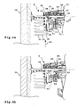
- the conveyor pawl part 41 is on the one hand from the engagement position E in a release position F swung out, see FIG.
- the two rollers 70 which form the slide follower, roll along guide tracks 84.
- the two slide tracks 84 are provided next to the slide guide channels 46 on the base body 21.
- Both the carriage guide channels 46 and the slide track 48 are suitably made of metal, whereas the main body housing 20 is advantageously made of plastic.
- the slide tracks 84 and the slide guide channels 46 are provided by metallic insert elements 87.
- the insert elements 87 are arranged on the inner sides of the main body housing 20 in the inner space 44.
- the slide tracks 84 have the screw end of the attachment towards slanting sections and subsequently in the direction of the coupling device 12 parallel sections 86.
- the slide tracks 84 extend in the region of the parallel sections 86 parallel to the slide displacement axis 47, in the region of the oblique sections 85 at an angle thereto.
- the removal of the conveyor pawl part 41 from the carriage housing 48 is particularly simple, in which the closure part 73 is removed from the carriage housing 48 without tools.
- the carriage housing 48 or the carriage 28 can be removed just as easily and without tools from the main body 21.
- the main body housing 20 is namely open at its side facing away from the coupling device 12 screw side, so that the carriage 28 can be introduced so to speak from the front into the main body housing 20.
- a guide lock 88 for locking the carriage 28 and for holding the carriage 28 on the main body 21 and the main body housing 20 is a guide lock 88, which is manually operable. If the guide lock 88 is unlocked, the carriage 28 can be removed from the main body 21.
- the guide lock 88 includes a locking member 89 movably mounted on the carriage 28.
- the locking member 89 is defined by a window at the top of the Carriage housing 48 actuated by pressure by an operator.
- the locking member 89 is loaded in its locking position by a spring 89.
- locking projections 91 of the locking member 89 are positioned so that they abut against locking stops 92 of the base body 21 and the carriage 28 is held on the housing 28.
- the locking projections 91 and the associated locking stops 92 limit that the carriage 28 is moved out of the main body housing 20 under the load of the carriage spring 60.
- the guide lock 88 can be manually operated by pressing a button, so that a disassembly of the attachment 10 is possible without tools.
- the bearing receptacle 69 for the sleeve 67 and the Drehachs republic 68 is open at the side, so that a simple removal is possible.
- the locking members 53 and 89 are also easily accessible when the carriage 28 is moved into the main body housing 20 inside.
- the spring assembly 74 also serves to move the conveyor pawl member 41 from its remote from the screwdriver tool 56, in the drawing lower position back towards the screwdriver tool 56, namely in the context of a delivery stroke in which the conveyor pawl member 41 is in engagement position E, that is engages the screw magazine belt 32 and promotes the next screw to be screwed 13 in the direction of the screwdriver tool 56.
- the inventive alignment of the pawl pivot axis 62 proves to be advantageous in that the spring assembly 74, so to speak central between the two Eingreifvorsprüngen 42 acts on the conveyor pawl part 41, so that any tensions, jams or the like are not to be feared.
Landscapes
- Engineering & Computer Science (AREA)
- Mechanical Engineering (AREA)
- Portable Nailing Machines And Staplers (AREA)
- Details Of Spanners, Wrenches, And Screw Drivers And Accessories (AREA)
- Automatic Tool Replacement In Machine Tools (AREA)
Applications Claiming Priority (1)
| Application Number | Priority Date | Filing Date | Title |
|---|---|---|---|
| DE102009024112.4A DE102009024112B4 (de) | 2009-06-06 | 2009-06-06 | Schraubenmagazin-Vorsatzgerät |
Publications (3)
| Publication Number | Publication Date |
|---|---|
| EP2258518A2 true EP2258518A2 (fr) | 2010-12-08 |
| EP2258518A3 EP2258518A3 (fr) | 2018-03-14 |
| EP2258518B1 EP2258518B1 (fr) | 2019-08-21 |
Family
ID=42855025
Family Applications (1)
| Application Number | Title | Priority Date | Filing Date |
|---|---|---|---|
| EP10003233.3A Active EP2258518B1 (fr) | 2009-06-06 | 2010-03-26 | Appareil adaptable à cartouche de vis |
Country Status (2)
| Country | Link |
|---|---|
| EP (1) | EP2258518B1 (fr) |
| DE (1) | DE102009024112B4 (fr) |
Cited By (26)
| Publication number | Priority date | Publication date | Assignee | Title |
|---|---|---|---|---|
| US8382414B2 (en) | 2010-01-11 | 2013-02-26 | National Nail Corp. | Threaded fastener and related method of installation |
| USD677147S1 (en) | 2010-01-13 | 2013-03-05 | National Nail Corp. | Screw |
| USD704018S1 (en) | 2012-01-04 | 2014-05-06 | National Nail Corp. | Fastener installation tool |
| EP2789426A1 (fr) * | 2013-03-14 | 2014-10-15 | Black & Decker Inc. | Embout et chargeur pour visseuse électrique |
| US8955210B2 (en) | 2010-01-13 | 2015-02-17 | National Nail Corp. | Fastener, installation tool and related method of use |
| USD725981S1 (en) | 2013-10-29 | 2015-04-07 | Black & Decker Inc. | Screwdriver with nosepiece |
| US9120214B2 (en) | 2010-01-13 | 2015-09-01 | National Nail Corp. | Fastener, installation tool and related method of use |
| US9144896B2 (en) | 2010-01-13 | 2015-09-29 | National Nail Corp. | Fastener, installation tool and related method of use |
| EP2489473A3 (fr) * | 2011-02-15 | 2017-01-25 | Metabowerke GmbH | Système de tournevis doté d'une pièce saillante de vissage de cartouche |
| US9802300B2 (en) | 2010-01-13 | 2017-10-31 | National Nail Corp. | Fastener, installation tool and related method of use |
| TWI632991B (zh) * | 2016-02-19 | 2018-08-21 | 國家釘子股份有限公司 | 張力饋送固定件安裝工具及其使用之相關方法 |
| USD842086S1 (en) | 2018-02-26 | 2019-03-05 | National Nail Corp. | Screw |
| US10286529B2 (en) | 2013-06-27 | 2019-05-14 | Makita Corporation | Screw-tightening power tool |
| US10821594B2 (en) | 2013-10-29 | 2020-11-03 | Black & Decker Inc. | Power tool with ergonomic handgrip |
| USD924044S1 (en) | 2019-11-20 | 2021-07-06 | National Nail Corp. | Fastener positioning device |
| US11149445B2 (en) | 2017-08-15 | 2021-10-19 | National Nail Corp. | Hidden fastener unit and related method of use |
| USD945870S1 (en) | 2020-11-17 | 2022-03-15 | National Nail Corp. | Fastener positioning device |
| US11603670B2 (en) | 2017-08-15 | 2023-03-14 | National Nail Corp. | Hidden fastener unit and related method of use |
| US11731252B2 (en) | 2021-01-29 | 2023-08-22 | National Nail Corp. | Screw guide and related method of use |
| US11840848B2 (en) | 2017-08-15 | 2023-12-12 | National Nail Corp. | Hidden fastener unit and related method of use |
| US11898357B2 (en) | 2017-08-15 | 2024-02-13 | National Nail Corp. | Hidden fastener unit and related method of use |
| US11920618B2 (en) | 2017-08-15 | 2024-03-05 | National Nail Corp. | Hidden fastener unit and related method of use |
| USD1019365S1 (en) | 2023-05-31 | 2024-03-26 | National Nail Corp. | Fastener positioning device |
| US11938596B1 (en) | 2023-01-26 | 2024-03-26 | National Nail Corp. | Fastener installation tool and related method of use |
| USD1022684S1 (en) | 2023-02-23 | 2024-04-16 | National Nail Corp. | Fastener positioning device |
| US12233523B2 (en) | 2020-12-07 | 2025-02-25 | Black & Decker Inc. | Power tool with multiple modes of operation and ergonomic handgrip |
Families Citing this family (3)
| Publication number | Priority date | Publication date | Assignee | Title |
|---|---|---|---|---|
| DE102009049011A1 (de) | 2009-10-10 | 2011-04-21 | Festool Gmbh | Hand-Werkzeugmaschine mit einer Hakenanordnung |
| DE102010026023A1 (de) | 2010-07-03 | 2012-01-05 | Festool Gmbh | Hand-Werkzeugmaschine mit einem Energiespeicher |
| US12297649B2 (en) | 2022-10-27 | 2025-05-13 | Primesource Building Products, Inc. | Deck clip |
Family Cites Families (8)
| Publication number | Priority date | Publication date | Assignee | Title |
|---|---|---|---|---|
| WO1999014017A2 (fr) * | 1997-09-12 | 1999-03-25 | Jalbert David B | Dispositif tournevis actionne par moteur |
| DE10047455A1 (de) * | 2000-09-26 | 2002-04-11 | Hilti Ag | Schraubvorrichtung für ein streifenförmiges Schraubenmagazin |
| DE20214489U1 (de) * | 2002-09-19 | 2004-02-19 | Helfer & Co. Kg | Gerät zum Eintreiben von Befestigern, insbesondere Schrauben o.dgl. |
| US6862963B2 (en) * | 2002-11-08 | 2005-03-08 | G. Lyle Habermehl | Split nosepiece for driving collated screws |
| DE102004025725B4 (de) | 2004-05-26 | 2007-10-18 | Fujitsu Siemens Computers Gmbh | Computergehäusebefestigungssystem |
| WO2006132684A2 (fr) | 2005-02-25 | 2006-12-14 | Duraspin Products Llc | Outil d'entrainement de vis portatif presentant une extremite frontale retractable |
| EP1932623A1 (fr) | 2006-12-13 | 2008-06-18 | Kwantex Research Inc. | Combinaison d'un bandeau à vis et son mécanisme d'avance pour un outil de vissage |
| DE102007026551A1 (de) | 2007-06-08 | 2008-12-11 | Evonik Degussa Gmbh | Pigmentpräparation, Verfahren zu deren Herstellung und Verwendung |
-
2009
- 2009-06-06 DE DE102009024112.4A patent/DE102009024112B4/de not_active Expired - Fee Related
-
2010
- 2010-03-26 EP EP10003233.3A patent/EP2258518B1/fr active Active
Non-Patent Citations (1)
| Title |
|---|
| None |
Cited By (47)
| Publication number | Priority date | Publication date | Assignee | Title |
|---|---|---|---|---|
| US8382414B2 (en) | 2010-01-11 | 2013-02-26 | National Nail Corp. | Threaded fastener and related method of installation |
| US8925644B2 (en) | 2010-01-13 | 2015-01-06 | National Nail Corp. | Fastener, installation tool and related method of use |
| US9051726B2 (en) | 2010-01-13 | 2015-06-09 | National Nail Corp. | Fastener, installation tool and related method of use |
| USD693210S1 (en) | 2010-01-13 | 2013-11-12 | National Nail Corp. | Screw |
| US8672204B2 (en) | 2010-01-13 | 2014-03-18 | National Nail Corp. | Fastener, installation tool and related method of use |
| US9751197B2 (en) | 2010-01-13 | 2017-09-05 | National Nail Corp. | Fastener, installation tool and related method of use |
| US8747043B2 (en) | 2010-01-13 | 2014-06-10 | National Nail Corp. | Fastener, installation tool and related method of use |
| US8480343B2 (en) | 2010-01-13 | 2013-07-09 | National Nail Corp. | Fastener, installation tool and related method of use |
| US10315295B2 (en) | 2010-01-13 | 2019-06-11 | National Nail Corp. | Fastener, installation tool and related method of use |
| US8955210B2 (en) | 2010-01-13 | 2015-02-17 | National Nail Corp. | Fastener, installation tool and related method of use |
| US9144896B2 (en) | 2010-01-13 | 2015-09-29 | National Nail Corp. | Fastener, installation tool and related method of use |
| USD677147S1 (en) | 2010-01-13 | 2013-03-05 | National Nail Corp. | Screw |
| US9120214B2 (en) | 2010-01-13 | 2015-09-01 | National Nail Corp. | Fastener, installation tool and related method of use |
| US9802300B2 (en) | 2010-01-13 | 2017-10-31 | National Nail Corp. | Fastener, installation tool and related method of use |
| US9784296B2 (en) | 2010-01-13 | 2017-10-10 | National Nail Corp. | Fastener, installation tool and related method of use |
| EP2489473A3 (fr) * | 2011-02-15 | 2017-01-25 | Metabowerke GmbH | Système de tournevis doté d'une pièce saillante de vissage de cartouche |
| USD704018S1 (en) | 2012-01-04 | 2014-05-06 | National Nail Corp. | Fastener installation tool |
| US11673241B2 (en) | 2013-03-14 | 2023-06-13 | Black & Decker Inc. | Nosepiece and magazine for power screwdriver |
| EP3050675A1 (fr) * | 2013-03-14 | 2016-08-03 | Black & Decker Inc. | Embout nasal et chargeur pour visseuse électrique |
| EP2789426A1 (fr) * | 2013-03-14 | 2014-10-15 | Black & Decker Inc. | Embout et chargeur pour visseuse électrique |
| US10406661B2 (en) | 2013-03-14 | 2019-09-10 | Black & Decker Inc. | Nosepiece and magazine for power screwdriver |
| US9616557B2 (en) | 2013-03-14 | 2017-04-11 | Black & Decker Inc. | Nosepiece and magazine for power screwdriver |
| US11090784B2 (en) | 2013-06-27 | 2021-08-17 | Makita Corporation | Screw-tightening power tool |
| US10286529B2 (en) | 2013-06-27 | 2019-05-14 | Makita Corporation | Screw-tightening power tool |
| USD739200S1 (en) | 2013-10-29 | 2015-09-22 | Black & Decker Inc. | Screwdriver |
| USD737647S1 (en) | 2013-10-29 | 2015-09-01 | Black & Decker Inc. | Nosepiece for screwdriver |
| USD725981S1 (en) | 2013-10-29 | 2015-04-07 | Black & Decker Inc. | Screwdriver with nosepiece |
| US10821594B2 (en) | 2013-10-29 | 2020-11-03 | Black & Decker Inc. | Power tool with ergonomic handgrip |
| TWI632991B (zh) * | 2016-02-19 | 2018-08-21 | 國家釘子股份有限公司 | 張力饋送固定件安裝工具及其使用之相關方法 |
| US11603670B2 (en) | 2017-08-15 | 2023-03-14 | National Nail Corp. | Hidden fastener unit and related method of use |
| US12221794B2 (en) | 2017-08-15 | 2025-02-11 | National Nail Corp. | Hidden fastener unit and related method of use |
| US11149445B2 (en) | 2017-08-15 | 2021-10-19 | National Nail Corp. | Hidden fastener unit and related method of use |
| US11840848B2 (en) | 2017-08-15 | 2023-12-12 | National Nail Corp. | Hidden fastener unit and related method of use |
| US11898357B2 (en) | 2017-08-15 | 2024-02-13 | National Nail Corp. | Hidden fastener unit and related method of use |
| US11920618B2 (en) | 2017-08-15 | 2024-03-05 | National Nail Corp. | Hidden fastener unit and related method of use |
| US12607020B2 (en) | 2017-08-15 | 2026-04-21 | National Nail Corp. | Hidden fastener unit and related method of use |
| US12264483B2 (en) | 2017-08-15 | 2025-04-01 | National Nail Corp. | Hidden fastener unit and related method of use |
| US12234654B2 (en) | 2017-08-15 | 2025-02-25 | National Nail Corp. | Hidden fastener unit and related method of use |
| USD842086S1 (en) | 2018-02-26 | 2019-03-05 | National Nail Corp. | Screw |
| USD924044S1 (en) | 2019-11-20 | 2021-07-06 | National Nail Corp. | Fastener positioning device |
| USD945870S1 (en) | 2020-11-17 | 2022-03-15 | National Nail Corp. | Fastener positioning device |
| US12233523B2 (en) | 2020-12-07 | 2025-02-25 | Black & Decker Inc. | Power tool with multiple modes of operation and ergonomic handgrip |
| US11731252B2 (en) | 2021-01-29 | 2023-08-22 | National Nail Corp. | Screw guide and related method of use |
| US11969863B2 (en) | 2021-01-29 | 2024-04-30 | National Nail Corp. | Screw guide and related method of use |
| US11938596B1 (en) | 2023-01-26 | 2024-03-26 | National Nail Corp. | Fastener installation tool and related method of use |
| USD1022684S1 (en) | 2023-02-23 | 2024-04-16 | National Nail Corp. | Fastener positioning device |
| USD1019365S1 (en) | 2023-05-31 | 2024-03-26 | National Nail Corp. | Fastener positioning device |
Also Published As
| Publication number | Publication date |
|---|---|
| EP2258518B1 (fr) | 2019-08-21 |
| EP2258518A3 (fr) | 2018-03-14 |
| DE102009024112A1 (de) | 2010-12-09 |
| DE102009024112B4 (de) | 2021-12-30 |
Similar Documents
| Publication | Publication Date | Title |
|---|---|---|
| EP2258518B1 (fr) | Appareil adaptable à cartouche de vis | |
| EP2851497B1 (fr) | Dispositif de montage réglable pour un élément coulissant et dispositif coulissant | |
| AT516391B1 (de) | Ausstoßvorrichtung für ein bewegbares Möbelteil | |
| DE102007045177B4 (de) | Verriegelungsvorrichtung | |
| DE19707235A1 (de) | Setzgerät mit Magazin für Befestigungselemente | |
| DE3038565C2 (de) | Heftapparat | |
| DE202018105217U1 (de) | Antriebsschlitten für ein Tor sowie Torantrieb | |
| AT18047U1 (de) | Möbelantrieb | |
| EP2449332B1 (fr) | Mécanisme d'armement et de désarmement pour arme à feu | |
| DE3141248C2 (de) | Einrichtung zum Zuführen von Schrauben für einen motorbetriebenen Schraubenzieher | |
| DE3623495A1 (de) | Handgeraet zum anbringen von schildchen | |
| DE2749342A1 (de) | Werkzeug zum spannen und schneiden von selbstverriegelungsbaendern | |
| EP1642686A2 (fr) | Support de perçage | |
| DE102018112183B3 (de) | Ratschenschlüssel | |
| DE10160096C1 (de) | Verschluss zum gegenseitigen Verriegeln zweier Bauteile | |
| DE19512273A1 (de) | Schloß mit umwendbarer Falle | |
| DE19943315B4 (de) | Vorrichtung zum lösbaren Festsetzen eines beweglichen Fahrzeugteils an einem stationären Fahrzeugteil | |
| DE4014042A1 (de) | Treibstangenschloss | |
| EP4245187A2 (fr) | Guide télescopique pour un élément de meuble mobile | |
| DE7710841U1 (de) | Klemme zum festklemmen von werkstuecken | |
| DE102010020655A1 (de) | Wasserpumpenzange | |
| DE102008004452B3 (de) | Verstellbarer Schraubenschlüssel | |
| EP3735919B1 (fr) | Instrument médical | |
| DE3205110A1 (de) | Zweiarmige handhebelpresse | |
| EP2039480B1 (fr) | Pistolet à boulons |
Legal Events
| Date | Code | Title | Description |
|---|---|---|---|
| PUAI | Public reference made under article 153(3) epc to a published international application that has entered the european phase |
Free format text: ORIGINAL CODE: 0009012 |
|
| AK | Designated contracting states |
Kind code of ref document: A2 Designated state(s): AT BE BG CH CY CZ DE DK EE ES FI FR GB GR HR HU IE IS IT LI LT LU LV MC MK MT NL NO PL PT RO SE SI SK SM TR |
|
| AX | Request for extension of the european patent |
Extension state: AL BA ME RS |
|
| RAP1 | Party data changed (applicant data changed or rights of an application transferred) |
Owner name: FESTOOL GROUP GMBH & CO. KG |
|
| RAP1 | Party data changed (applicant data changed or rights of an application transferred) |
Owner name: FESTOOL GMBH |
|
| PUAL | Search report despatched |
Free format text: ORIGINAL CODE: 0009013 |
|
| AK | Designated contracting states |
Kind code of ref document: A3 Designated state(s): AT BE BG CH CY CZ DE DK EE ES FI FR GB GR HR HU IE IS IT LI LT LU LV MC MK MT NL NO PL PT RO SE SI SK SM TR |
|
| AX | Request for extension of the european patent |
Extension state: AL BA ME RS |
|
| RIC1 | Information provided on ipc code assigned before grant |
Ipc: B25B 23/04 20060101AFI20180208BHEP |
|
| STAA | Information on the status of an ep patent application or granted ep patent |
Free format text: STATUS: REQUEST FOR EXAMINATION WAS MADE |
|
| 17P | Request for examination filed |
Effective date: 20180831 |
|
| RBV | Designated contracting states (corrected) |
Designated state(s): AT BE BG CH CY CZ DE DK EE ES FI FR GB GR HR HU IE IS IT LI LT LU LV MC MK MT NL NO PL PT RO SE SI SK SM TR |
|
| GRAP | Despatch of communication of intention to grant a patent |
Free format text: ORIGINAL CODE: EPIDOSNIGR1 |
|
| STAA | Information on the status of an ep patent application or granted ep patent |
Free format text: STATUS: GRANT OF PATENT IS INTENDED |
|
| INTG | Intention to grant announced |
Effective date: 20190424 |
|
| RIN1 | Information on inventor provided before grant (corrected) |
Inventor name: GRULICH, PETR |
|
| GRAS | Grant fee paid |
Free format text: ORIGINAL CODE: EPIDOSNIGR3 |
|
| GRAA | (expected) grant |
Free format text: ORIGINAL CODE: 0009210 |
|
| STAA | Information on the status of an ep patent application or granted ep patent |
Free format text: STATUS: THE PATENT HAS BEEN GRANTED |
|
| AK | Designated contracting states |
Kind code of ref document: B1 Designated state(s): AT BE BG CH CY CZ DE DK EE ES FI FR GB GR HR HU IE IS IT LI LT LU LV MC MK MT NL NO PL PT RO SE SI SK SM TR |
|
| REG | Reference to a national code |
Ref country code: GB Ref legal event code: FG4D Free format text: NOT ENGLISH |
|
| REG | Reference to a national code |
Ref country code: CH Ref legal event code: EP |
|
| REG | Reference to a national code |
Ref country code: DE Ref legal event code: R096 Ref document number: 502010016201 Country of ref document: DE |
|
| REG | Reference to a national code |
Ref country code: AT Ref legal event code: REF Ref document number: 1169172 Country of ref document: AT Kind code of ref document: T Effective date: 20190915 |
|
| REG | Reference to a national code |
Ref country code: IE Ref legal event code: FG4D Free format text: LANGUAGE OF EP DOCUMENT: GERMAN |
|
| REG | Reference to a national code |
Ref country code: SE Ref legal event code: TRGR |
|
| REG | Reference to a national code |
Ref country code: NL Ref legal event code: FP |
|
| REG | Reference to a national code |
Ref country code: LT Ref legal event code: MG4D |
|
| PG25 | Lapsed in a contracting state [announced via postgrant information from national office to epo] |
Ref country code: FI Free format text: LAPSE BECAUSE OF FAILURE TO SUBMIT A TRANSLATION OF THE DESCRIPTION OR TO PAY THE FEE WITHIN THE PRESCRIBED TIME-LIMIT Effective date: 20190821 Ref country code: PT Free format text: LAPSE BECAUSE OF FAILURE TO SUBMIT A TRANSLATION OF THE DESCRIPTION OR TO PAY THE FEE WITHIN THE PRESCRIBED TIME-LIMIT Effective date: 20191223 Ref country code: HR Free format text: LAPSE BECAUSE OF FAILURE TO SUBMIT A TRANSLATION OF THE DESCRIPTION OR TO PAY THE FEE WITHIN THE PRESCRIBED TIME-LIMIT Effective date: 20190821 Ref country code: BG Free format text: LAPSE BECAUSE OF FAILURE TO SUBMIT A TRANSLATION OF THE DESCRIPTION OR TO PAY THE FEE WITHIN THE PRESCRIBED TIME-LIMIT Effective date: 20191121 Ref country code: LT Free format text: LAPSE BECAUSE OF FAILURE TO SUBMIT A TRANSLATION OF THE DESCRIPTION OR TO PAY THE FEE WITHIN THE PRESCRIBED TIME-LIMIT Effective date: 20190821 Ref country code: NO Free format text: LAPSE BECAUSE OF FAILURE TO SUBMIT A TRANSLATION OF THE DESCRIPTION OR TO PAY THE FEE WITHIN THE PRESCRIBED TIME-LIMIT Effective date: 20191121 |
|
| PG25 | Lapsed in a contracting state [announced via postgrant information from national office to epo] |
Ref country code: LV Free format text: LAPSE BECAUSE OF FAILURE TO SUBMIT A TRANSLATION OF THE DESCRIPTION OR TO PAY THE FEE WITHIN THE PRESCRIBED TIME-LIMIT Effective date: 20190821 Ref country code: GR Free format text: LAPSE BECAUSE OF FAILURE TO SUBMIT A TRANSLATION OF THE DESCRIPTION OR TO PAY THE FEE WITHIN THE PRESCRIBED TIME-LIMIT Effective date: 20191122 Ref country code: ES Free format text: LAPSE BECAUSE OF FAILURE TO SUBMIT A TRANSLATION OF THE DESCRIPTION OR TO PAY THE FEE WITHIN THE PRESCRIBED TIME-LIMIT Effective date: 20190821 Ref country code: IS Free format text: LAPSE BECAUSE OF FAILURE TO SUBMIT A TRANSLATION OF THE DESCRIPTION OR TO PAY THE FEE WITHIN THE PRESCRIBED TIME-LIMIT Effective date: 20191221 |
|
| PG25 | Lapsed in a contracting state [announced via postgrant information from national office to epo] |
Ref country code: TR Free format text: LAPSE BECAUSE OF FAILURE TO SUBMIT A TRANSLATION OF THE DESCRIPTION OR TO PAY THE FEE WITHIN THE PRESCRIBED TIME-LIMIT Effective date: 20190821 |
|
| PG25 | Lapsed in a contracting state [announced via postgrant information from national office to epo] |
Ref country code: EE Free format text: LAPSE BECAUSE OF FAILURE TO SUBMIT A TRANSLATION OF THE DESCRIPTION OR TO PAY THE FEE WITHIN THE PRESCRIBED TIME-LIMIT Effective date: 20190821 Ref country code: PL Free format text: LAPSE BECAUSE OF FAILURE TO SUBMIT A TRANSLATION OF THE DESCRIPTION OR TO PAY THE FEE WITHIN THE PRESCRIBED TIME-LIMIT Effective date: 20190821 Ref country code: RO Free format text: LAPSE BECAUSE OF FAILURE TO SUBMIT A TRANSLATION OF THE DESCRIPTION OR TO PAY THE FEE WITHIN THE PRESCRIBED TIME-LIMIT Effective date: 20190821 Ref country code: DK Free format text: LAPSE BECAUSE OF FAILURE TO SUBMIT A TRANSLATION OF THE DESCRIPTION OR TO PAY THE FEE WITHIN THE PRESCRIBED TIME-LIMIT Effective date: 20190821 Ref country code: IT Free format text: LAPSE BECAUSE OF FAILURE TO SUBMIT A TRANSLATION OF THE DESCRIPTION OR TO PAY THE FEE WITHIN THE PRESCRIBED TIME-LIMIT Effective date: 20190821 |
|
| PG25 | Lapsed in a contracting state [announced via postgrant information from national office to epo] |
Ref country code: CZ Free format text: LAPSE BECAUSE OF FAILURE TO SUBMIT A TRANSLATION OF THE DESCRIPTION OR TO PAY THE FEE WITHIN THE PRESCRIBED TIME-LIMIT Effective date: 20190821 Ref country code: SK Free format text: LAPSE BECAUSE OF FAILURE TO SUBMIT A TRANSLATION OF THE DESCRIPTION OR TO PAY THE FEE WITHIN THE PRESCRIBED TIME-LIMIT Effective date: 20190821 Ref country code: SM Free format text: LAPSE BECAUSE OF FAILURE TO SUBMIT A TRANSLATION OF THE DESCRIPTION OR TO PAY THE FEE WITHIN THE PRESCRIBED TIME-LIMIT Effective date: 20190821 Ref country code: IS Free format text: LAPSE BECAUSE OF FAILURE TO SUBMIT A TRANSLATION OF THE DESCRIPTION OR TO PAY THE FEE WITHIN THE PRESCRIBED TIME-LIMIT Effective date: 20200224 |
|
| REG | Reference to a national code |
Ref country code: DE Ref legal event code: R097 Ref document number: 502010016201 Country of ref document: DE |
|
| PLBE | No opposition filed within time limit |
Free format text: ORIGINAL CODE: 0009261 |
|
| STAA | Information on the status of an ep patent application or granted ep patent |
Free format text: STATUS: NO OPPOSITION FILED WITHIN TIME LIMIT |
|
| PG2D | Information on lapse in contracting state deleted |
Ref country code: IS |
|
| 26N | No opposition filed |
Effective date: 20200603 |
|
| PG25 | Lapsed in a contracting state [announced via postgrant information from national office to epo] |
Ref country code: SI Free format text: LAPSE BECAUSE OF FAILURE TO SUBMIT A TRANSLATION OF THE DESCRIPTION OR TO PAY THE FEE WITHIN THE PRESCRIBED TIME-LIMIT Effective date: 20190821 |
|
| PG25 | Lapsed in a contracting state [announced via postgrant information from national office to epo] |
Ref country code: MC Free format text: LAPSE BECAUSE OF FAILURE TO SUBMIT A TRANSLATION OF THE DESCRIPTION OR TO PAY THE FEE WITHIN THE PRESCRIBED TIME-LIMIT Effective date: 20190821 |
|
| REG | Reference to a national code |
Ref country code: CH Ref legal event code: PL |
|
| REG | Reference to a national code |
Ref country code: BE Ref legal event code: MM Effective date: 20200331 |
|
| PG25 | Lapsed in a contracting state [announced via postgrant information from national office to epo] |
Ref country code: LU Free format text: LAPSE BECAUSE OF NON-PAYMENT OF DUE FEES Effective date: 20200326 |
|
| PG25 | Lapsed in a contracting state [announced via postgrant information from national office to epo] |
Ref country code: IE Free format text: LAPSE BECAUSE OF NON-PAYMENT OF DUE FEES Effective date: 20200326 Ref country code: CH Free format text: LAPSE BECAUSE OF NON-PAYMENT OF DUE FEES Effective date: 20200331 Ref country code: LI Free format text: LAPSE BECAUSE OF NON-PAYMENT OF DUE FEES Effective date: 20200331 |
|
| PG25 | Lapsed in a contracting state [announced via postgrant information from national office to epo] |
Ref country code: BE Free format text: LAPSE BECAUSE OF NON-PAYMENT OF DUE FEES Effective date: 20200331 |
|
| REG | Reference to a national code |
Ref country code: AT Ref legal event code: MM01 Ref document number: 1169172 Country of ref document: AT Kind code of ref document: T Effective date: 20200326 |
|
| PG25 | Lapsed in a contracting state [announced via postgrant information from national office to epo] |
Ref country code: AT Free format text: LAPSE BECAUSE OF NON-PAYMENT OF DUE FEES Effective date: 20200326 |
|
| PG25 | Lapsed in a contracting state [announced via postgrant information from national office to epo] |
Ref country code: MT Free format text: LAPSE BECAUSE OF FAILURE TO SUBMIT A TRANSLATION OF THE DESCRIPTION OR TO PAY THE FEE WITHIN THE PRESCRIBED TIME-LIMIT Effective date: 20190821 Ref country code: CY Free format text: LAPSE BECAUSE OF FAILURE TO SUBMIT A TRANSLATION OF THE DESCRIPTION OR TO PAY THE FEE WITHIN THE PRESCRIBED TIME-LIMIT Effective date: 20190821 |
|
| PG25 | Lapsed in a contracting state [announced via postgrant information from national office to epo] |
Ref country code: MK Free format text: LAPSE BECAUSE OF FAILURE TO SUBMIT A TRANSLATION OF THE DESCRIPTION OR TO PAY THE FEE WITHIN THE PRESCRIBED TIME-LIMIT Effective date: 20190821 |
|
| P01 | Opt-out of the competence of the unified patent court (upc) registered |
Effective date: 20230517 |
|
| PGFP | Annual fee paid to national office [announced via postgrant information from national office to epo] |
Ref country code: SE Payment date: 20250321 Year of fee payment: 16 |
|
| PGFP | Annual fee paid to national office [announced via postgrant information from national office to epo] |
Ref country code: DE Payment date: 20250212 Year of fee payment: 16 |
|
| PGFP | Annual fee paid to national office [announced via postgrant information from national office to epo] |
Ref country code: NL Payment date: 20250319 Year of fee payment: 16 |
|
| PGFP | Annual fee paid to national office [announced via postgrant information from national office to epo] |
Ref country code: FR Payment date: 20250218 Year of fee payment: 16 |
|
| PGFP | Annual fee paid to national office [announced via postgrant information from national office to epo] |
Ref country code: GB Payment date: 20250218 Year of fee payment: 16 |