EP2259130A2 - Module à cristaux liquides - Google Patents
Module à cristaux liquides Download PDFInfo
- Publication number
- EP2259130A2 EP2259130A2 EP10163864A EP10163864A EP2259130A2 EP 2259130 A2 EP2259130 A2 EP 2259130A2 EP 10163864 A EP10163864 A EP 10163864A EP 10163864 A EP10163864 A EP 10163864A EP 2259130 A2 EP2259130 A2 EP 2259130A2
- Authority
- EP
- European Patent Office
- Prior art keywords
- diffuser plate
- liquid crystal
- light diffuser
- slope
- pair
- Prior art date
- Legal status (The legal status is an assumption and is not a legal conclusion. Google has not performed a legal analysis and makes no representation as to the accuracy of the status listed.)
- Withdrawn
Links
- 239000004973 liquid crystal related substance Substances 0.000 title claims abstract description 86
- 229920003002 synthetic resin Polymers 0.000 claims abstract description 11
- 239000000057 synthetic resin Substances 0.000 claims abstract description 11
- 238000002834 transmittance Methods 0.000 description 4
- 238000005452 bending Methods 0.000 description 3
- 230000006866 deterioration Effects 0.000 description 2
- 230000000694 effects Effects 0.000 description 2
- 239000000463 material Substances 0.000 description 2
- 239000002184 metal Substances 0.000 description 2
- 238000000034 method Methods 0.000 description 2
- 230000015572 biosynthetic process Effects 0.000 description 1
- 239000003795 chemical substances by application Substances 0.000 description 1
- 230000007423 decrease Effects 0.000 description 1
Images

Classifications
-
- G—PHYSICS
- G02—OPTICS
- G02F—OPTICAL DEVICES OR ARRANGEMENTS FOR THE CONTROL OF LIGHT BY MODIFICATION OF THE OPTICAL PROPERTIES OF THE MEDIA OF THE ELEMENTS INVOLVED THEREIN; NON-LINEAR OPTICS; FREQUENCY-CHANGING OF LIGHT; OPTICAL LOGIC ELEMENTS; OPTICAL ANALOGUE/DIGITAL CONVERTERS
- G02F1/00—Devices or arrangements for the control of the intensity, colour, phase, polarisation or direction of light arriving from an independent light source, e.g. switching, gating or modulating; Non-linear optics
- G02F1/01—Devices or arrangements for the control of the intensity, colour, phase, polarisation or direction of light arriving from an independent light source, e.g. switching, gating or modulating; Non-linear optics for the control of the intensity, phase, polarisation or colour
- G02F1/13—Devices or arrangements for the control of the intensity, colour, phase, polarisation or direction of light arriving from an independent light source, e.g. switching, gating or modulating; Non-linear optics for the control of the intensity, phase, polarisation or colour based on liquid crystals, e.g. single liquid crystal display cells
- G02F1/133—Constructional arrangements; Operation of liquid crystal cells; Circuit arrangements
- G02F1/1333—Constructional arrangements; Manufacturing methods
- G02F1/133308—Support structures for LCD panels, e.g. frames or bezels
-
- G—PHYSICS
- G02—OPTICS
- G02F—OPTICAL DEVICES OR ARRANGEMENTS FOR THE CONTROL OF LIGHT BY MODIFICATION OF THE OPTICAL PROPERTIES OF THE MEDIA OF THE ELEMENTS INVOLVED THEREIN; NON-LINEAR OPTICS; FREQUENCY-CHANGING OF LIGHT; OPTICAL LOGIC ELEMENTS; OPTICAL ANALOGUE/DIGITAL CONVERTERS
- G02F1/00—Devices or arrangements for the control of the intensity, colour, phase, polarisation or direction of light arriving from an independent light source, e.g. switching, gating or modulating; Non-linear optics
- G02F1/01—Devices or arrangements for the control of the intensity, colour, phase, polarisation or direction of light arriving from an independent light source, e.g. switching, gating or modulating; Non-linear optics for the control of the intensity, phase, polarisation or colour
- G02F1/13—Devices or arrangements for the control of the intensity, colour, phase, polarisation or direction of light arriving from an independent light source, e.g. switching, gating or modulating; Non-linear optics for the control of the intensity, phase, polarisation or colour based on liquid crystals, e.g. single liquid crystal display cells
- G02F1/133—Constructional arrangements; Operation of liquid crystal cells; Circuit arrangements
- G02F1/1333—Constructional arrangements; Manufacturing methods
- G02F1/1335—Structural association of cells with optical devices, e.g. polarisers or reflectors
- G02F1/1336—Illuminating devices
- G02F1/133602—Direct backlight
- G02F1/133606—Direct backlight including a specially adapted diffusing, scattering or light controlling members
-
- G—PHYSICS
- G02—OPTICS
- G02F—OPTICAL DEVICES OR ARRANGEMENTS FOR THE CONTROL OF LIGHT BY MODIFICATION OF THE OPTICAL PROPERTIES OF THE MEDIA OF THE ELEMENTS INVOLVED THEREIN; NON-LINEAR OPTICS; FREQUENCY-CHANGING OF LIGHT; OPTICAL LOGIC ELEMENTS; OPTICAL ANALOGUE/DIGITAL CONVERTERS
- G02F1/00—Devices or arrangements for the control of the intensity, colour, phase, polarisation or direction of light arriving from an independent light source, e.g. switching, gating or modulating; Non-linear optics
- G02F1/01—Devices or arrangements for the control of the intensity, colour, phase, polarisation or direction of light arriving from an independent light source, e.g. switching, gating or modulating; Non-linear optics for the control of the intensity, phase, polarisation or colour
- G02F1/13—Devices or arrangements for the control of the intensity, colour, phase, polarisation or direction of light arriving from an independent light source, e.g. switching, gating or modulating; Non-linear optics for the control of the intensity, phase, polarisation or colour based on liquid crystals, e.g. single liquid crystal display cells
- G02F1/133—Constructional arrangements; Operation of liquid crystal cells; Circuit arrangements
- G02F1/1333—Constructional arrangements; Manufacturing methods
- G02F1/1335—Structural association of cells with optical devices, e.g. polarisers or reflectors
- G02F1/1336—Illuminating devices
- G02F1/133602—Direct backlight
- G02F1/133608—Direct backlight including particular frames or supporting means
-
- G—PHYSICS
- G02—OPTICS
- G02F—OPTICAL DEVICES OR ARRANGEMENTS FOR THE CONTROL OF LIGHT BY MODIFICATION OF THE OPTICAL PROPERTIES OF THE MEDIA OF THE ELEMENTS INVOLVED THEREIN; NON-LINEAR OPTICS; FREQUENCY-CHANGING OF LIGHT; OPTICAL LOGIC ELEMENTS; OPTICAL ANALOGUE/DIGITAL CONVERTERS
- G02F1/00—Devices or arrangements for the control of the intensity, colour, phase, polarisation or direction of light arriving from an independent light source, e.g. switching, gating or modulating; Non-linear optics
- G02F1/01—Devices or arrangements for the control of the intensity, colour, phase, polarisation or direction of light arriving from an independent light source, e.g. switching, gating or modulating; Non-linear optics for the control of the intensity, phase, polarisation or colour
- G02F1/13—Devices or arrangements for the control of the intensity, colour, phase, polarisation or direction of light arriving from an independent light source, e.g. switching, gating or modulating; Non-linear optics for the control of the intensity, phase, polarisation or colour based on liquid crystals, e.g. single liquid crystal display cells
- G02F1/133—Constructional arrangements; Operation of liquid crystal cells; Circuit arrangements
- G02F1/1333—Constructional arrangements; Manufacturing methods
- G02F1/133308—Support structures for LCD panels, e.g. frames or bezels
- G02F1/133317—Intermediate frames, e.g. between backlight housing and front frame
-
- G—PHYSICS
- G02—OPTICS
- G02F—OPTICAL DEVICES OR ARRANGEMENTS FOR THE CONTROL OF LIGHT BY MODIFICATION OF THE OPTICAL PROPERTIES OF THE MEDIA OF THE ELEMENTS INVOLVED THEREIN; NON-LINEAR OPTICS; FREQUENCY-CHANGING OF LIGHT; OPTICAL LOGIC ELEMENTS; OPTICAL ANALOGUE/DIGITAL CONVERTERS
- G02F2201/00—Constructional arrangements not provided for in groups G02F1/00 - G02F7/00
- G02F2201/50—Protective arrangements
- G02F2201/503—Arrangements improving the resistance to shock
Definitions
- the present invention relates to a liquid crystal module to be installed in an electronic device such as a television, a personal computer, or the like. More particularly, the present invention relates to a liquid crystal module which is capable of solving a problem occurring when a light diffuser plate which is made of synthetic resin and is disposed at a rear side of a liquid crystal panel is formed integrally with a frame portion which is made of synthetic resin and is used for fixing the light diffuser plate to the rear frame.
- edge portions of an light diffuser plate which is disposed at a rear side of a liquid crystal panel is overlapped with side plates of a rear frame in which a light source such as a cold cathode tube is accommodated.
- the edge portions of the light diffuser plate is pressed and fixed to the rear frame by a frame component (a cell guide) made of synthetic resin.
- liquid crystal module in which the light diffuser plate is formed integrally with the frame component (the cell guide) made of synthetic resin.
- a cushion member 106 is disposed inside a frame portion 105a which is formed integrally with the light diffuser plate 105, and an edge portion of the liquid crystal panel 108 is supported by this cushion member 106.
- Patent Document 1 discloses a liquid crystal display device in which a frame is formed integrally with a circumference of a diffuser plate and a circumferential edge portion of a liquid crystal panel is directly supported by this frame
- Patent Document 2 discloses a direct backlight using a diffuser plate-integrated upper frame in which a diffuser plate is formed integrally with a circumferential edge portion of an upper frame, and an circumferential edge portion of a liquid crystal panel is supported by a stepped support portion of the frame.
- the cushion member 106 is disposed inside the frame portion 105a of the light diffuser plate 105 to support the edge portion of the liquid crystal panel 108, the cushion member 106 is likely to be inside an imaginary line L1 indicating a viewing angle range of a display surface of the liquid crystal panel 108. Accordingly, the cushion member 106 may be viewable from the display surface of the liquid crystal panel 108, and it deteriorates the display quality.
- a liquid crystal module comprising: a rear frame provided with a pair of side plates which are formed along a pair of long opposite sides of the rear frame; a light diffuser plate comprised of synthetic resin and provided with a pair of frame portions which are formed integrally with the light diffuser plate, disposed along a pair of long opposite sides of the light diffuser plate and respectively attached to the side plates of the rear frame; a pair of cushion members disposed along and inside the frame portions of the light diffuser plate; and a liquid crystal panel having an upper edge portion and lower edge portion which are supported by the cushion members, wherein the light diffuser plate is provided with a pair of slope portions which are formed integrally with the light diffuser plate and disposed along and inside the cushion members, and wherein the height of each slope portion increases toward an adjacent cushion member for concealing the cushion members.
- a top portion of each slope portion may protrude outside of a viewing angle range of a display surface of the liquid crystal panel.
- the light diffuser plate may be provided with a concave portion at an opposite side of each slope portion.
- the light diffuser plate may be provided with a curved portion between a slope surface of the slope portion and a flat surface of the light diffuser plate so that the flat surface is smoothly continuous with the slope surface.
- the edge portions of the liquid crystal panel is supported by the cushion members. Even when a user sees the display surface of the liquid crystal panel at an angle along the imaginary line indicating the viewing angle range, the cushion members are concealed by the slope portions which are formed with the light diffuser plate so as to protrude from the surface of the light diffuser plate and are disposed inside the cushion members. Since the diffused light emitted from the slope portions comes into view, the user cannot see the cushion members. In addition, even when the slope portions for concealing the cushion members are formed integrally with the light diffuser plate, since the bending angle between the slope surface of each slope portion and the flat surface of the light diffuser plate is an obtuse angle, the bent edge portion is unlikely to be seen.
- the above-configured liquid crystal module can improve the display quality.
- the slope portions are integrally formed with the diffuser plate, the cushion members is interposed and exactly located between the frame portion of the light diffuser plate and the slope portions.
- a light beam transmittance of the light diffuser plate may be locally slightly deteriorated. If the light diffuser plate is provided with a concave portion at an opposite side of each slope portion, it can suppress the increase in thickness in the portion where the slope portions are integrally formed, thereby preventing the local deterioration of the light beam transmittance. As a result, it is possible to prevent the variation in brightness on the display surface of the liquid crystal panel.
- the light diffuser plate is provided with a curved portion between a slope surface of the slope portion and a flat surface of the light diffuser plate so that the flat surface is smoothly continuous with the slope surface, there is no bent edge between the light diffuser plate and the slope portions, so that the curved portion cannot be seen from the display surface of the liquid crystal panel, thereby further improving the display quality.
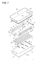
- a liquid crystal module shown in Figs. 1 to 3 is a large-sized liquid crystal module to be installed in liquid crystal television with a large screen.
- the liquid crystal module includes a rear frame 1, a reflector sheet 2, U-shaped cold cathode tubes 3, lamp holders 4, a light diffuser plate 5, a pair of cushion members 6, a pair of lamp frames 7, a liquid crystal panel 8, bezels 9a and 9b.
- the rear frame 1 is a shallow box-shaped rear frame formed by bending a sheet metal, and the reflector sheet 2 is provided inside of the rear frame 1.
- a plurality (five in this embodiment) of U-shaped cold cathode tubes 3 are arranged in parallel with each other on the reflector sheet 2.
- the U-shaped cold cathode tubes 3 are supported by a plurality (six in this embodiment) of lamp holders 4.
- Each lamp holder 4 is provided with holding portions 4a which fix and hold the U-shaped cold cathode tubes 3, as shown in Fig. 1 .
- the four lamp holders 4 holding center portions of the U-shaped cold cathode tubes 3 are provided with a post 4b supporting the light diffuser plate 5 from below to prevent bending of the light diffuser plate.
- Lamp sockets 3a are attached to end portions of the U-shaped cold cathode tubes 3.
- the lamp sockets 3a are fixed and held into opening portions 1c which are provided in a bottom plate 1b of the rear frame 1 along a short side plate 1a (left side plate) of the rear frame 1.
- Lead wires (not shown) of the U-shaped cold cathode tubes 3 are drawn out from each of the lamp sockets 3a toward a rear side of the rear frame 1.
- Both ends of the U-shaped cold cathode tubes 3 are covered by lamp frames 7 attached to left and right short side plates 1a and 1b of the rear frame 1 to reduce variation in brightness of the lamp socket 3a.
- the lamp frames 7 also serve as a cell guide.
- convex portions 7a are provided on the upper surface of the lamp frame 7 which supports the edge portion of the liquid crystal panel 8, in the vicinity of both end portions of the upper surface to position the liquid crystal panel 8 in left and right direction.
- both end portions of the upper surface of the lamp frame 7 is provided with a horizontal groove portion 7b into which the edge portion of the light diffuser plate 5 is inserted.
- the lamp frame 7 is made of white synthetic resin so as to serve as a light reflective plate.
- the light diffuser plate 5 disposed at the rear side of the liquid crystal panel 8 is made of transparent synthetic resin containing a light diffusing agent, and uniformly diffuses direct light from the U-shaped cold cathode tubes 3 or reflected light from the reflector sheet 2 to irradiate light onto the liquid crystal panel 8 and thus eliminate the variation in brightness on the display surface.
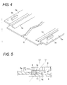
- Frame portions 5a and 5b serving as a cell guide are formed integrally with upper and lower long opposite sides of the light diffuser plate 5, as shown in Figs. 1 and 4 .
- Convex portions 5b are provided in the vicinity of both end portions of the respective frame portions 5a to position the liquid crystal panel 8 in up and down direction.
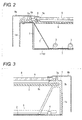
- the light diffuser plate 5 is attached to the rear frame 1 by disposing the frame portions 5a of the light diffuser plate 5 on the upper and lower long opposite side plates 1d (double side plates bent in a reversed U-shape) of the rear frame 1, as shown in Fig. 2 , and inserting the left and right edge portions of the light diffuser plate 5 into the horizontal groove portion 7b of the lamp frame 7, as shown in Fig. 3 .
- long and thin cushion members 6 and 6 having a light shielding property are disposed along and inside the frame portions 5a of the light diffuser plate 5.
- the upper and lower edge portions of the liquid crystal panel 8 along the long opposite sides are supported by the cushion members 6, and are positioned by the positioning convex portions 5b of the frame portions 5a of the light diffuser plate 5 so that the liquid crystal panel 8 does not move in the up and down direction.
- the left and right edge portions of the liquid crystal panel 8 along the opposite short sides are supported by the upper surfaces of the lamp frames 7, as shown in Fig. 3 , and are positioned by the positioning convex portions 7a so that the liquid crystal panel 8 does not move in the left and right direction.
- X-wiring boards (X-PCB) 10a and 10b which have been divided into two segments are connected to the long side edge portion of the liquid crystal panel 8 via a plurality of chip-on-films (COF) 11 on which a source drive IC chip is mounted.
- a Y-wiring board (Y-PCB) 13 is connected to the short side edge portion of the liquid crystal panel 8 via chip-on-films (COF) 12 on which a gate drive IC chip is mounted.
- the X-wiring boards 10a and 10b and the Y-wiring board 13 are fixed to the double-side plate 1d along one long side of the rear frame 1 and the outer surface of the side plate 1a along one short side, respectively.
- Slope portions 5c for concealing the cushion members 6 are formed integrally with the light diffuser plate 5 and disposed inside the cushion members 6.
- Each slope portion 5c has a slope surface 5d which is inclined in such a manner that the height of the slope portion 5c increases toward an adjacent cushion member 6.
- Each slope portion 5c has a long and thin band shape along each cushion member 6 and integrally protrudes from the surface of the light diffuser plate.
- a top portion 5e of each slope portion 5c slightly protrudes outside of a viewing angle range of the display surface of the liquid crystal panel 8, which is indicated by an imaginary line L1.
- an imaginary line L2 indicates an end of a display range of the liquid crystal panel 8.
- the slope portions 5c are formed integrally with the light diffuser plate 5, even when a user sees the display surface of the liquid crystal panel 8 at an angle along the imaginary line L1 indicating the viewing angle range, the portion of the cushion members 6 which enters into the viewing angle range indicated by the imaginary line L1, is completely concealed by the slope portions 5c. Since the diffused light emitting from the slope portions 5c comes into view, the cushion members 6 are not seen from the user. In addition, since the angle ⁇ between the slope surface 5d of each slope portion 5c and a flat surface 5f of the light diffuser plate 5 is an obtuse angle, the bent edge portion 5g is unlikely to be seen.
- the cushion member 6 since the cushion member 6 has the light shielding property, light does not leak from the edge portion of the liquid crystal panel 8. Consequently, the liquid crystal module has good display quality.
- the cushion member 6 is interposed and exactly positioned between the frame portions 5a and the slope portions 5c of the light diffuser plate 5.
- the inclined angle of the slope surface 5d of the slope portion 5c with respect to the flat surface 5f is not particularly limited, but if the inclined angle is remarkably large, the angle ⁇ between the slope surface 5d of the slope portion 5c and the flat surface 5f of the light diffuser plate 5 gets closer to a right angle from the obtuse angle, so that the bent edge 5g may be seen from the display surface of the liquid crystal panel 8. Therefore, it is preferable that the inclined angle ⁇ of the slope surface 5d is set to be 45° or less and the angle ⁇ is set to be 135° or more.
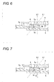
- the light diffuser plate 5 may be provided with a curved portion 5h between the slope surface 5d of the slope portion 5c and the flat surface 5f such that the flat surface 5f is smoothly continuous with the slope surface 5d.
- the curved portion 5h is provided, the above-mentioned bent edge 5g is completely removed, so that the possibility in which the cushion member is seen from the display surface of the liquid crystal panel 8 is absolutely eliminated, thereby further improving the display quality.
- the slope portion 5c is formed integrally with the surface of the light diffuser plate 5, there is no concern in that a negative effect such as the variation in brightness occurs at the display surface of the liquid crystal panel 8.
- the portion of the light diffuser plate 5, where the slope portion 5c is integrally formed becomes slightly thick relative to the other portion of the light diffuser plate 5, a light beam transmittance of the light diffuser plate 5 may be locally slightly deteriorated, so that the variation in brightness may occur slightly at the display surface of the liquid crystal panel 8.
- the light diffuser plate 5 may be provided with a concave portion 5i at an opposite side of each slope portion 5c.
- the portion of the light diffuser plate 5 where the slope portion 5c is integrally formed is provided with a concave portion 5i at the rear side thereof. If the concave portion 5i is formed, it can suppress the increase in thickness in the portion where the slope portions 5c are integrally formed, thereby preventing the local deterioration of the light beam transmittance. As a result, there is an advantage in that it is possible to eliminate the variation in brightness of the display surface of the liquid crystal panel 8.
- the light diffuser plate 5 is formed integrally with the frame portions 5a by using the transparent synthetic resin containing the light diffusing material.
- the frame portions 5a may be integrally formed with the light diffuser plate 5 by using colored synthetic resin having a light shielding property, and no light diffusing material by using a two-color formation method. In this way, there is an advantage that it is possible to eliminate the concern that the light leaks from the frame portions 5a.
- the frame portions 5a are formed integrally with upper and lower long opposite sides of the light diffuser plate 5 and the slope portions 5c are formed integrally with the light diffuser plate 5 and are disposed inside the cushion members 6 which are disposed along the frame portions 5a.
- the frame portions 5a are formed integrally with four sides of the light diffuser plate 5, the slope portion 5c protrudes in the frame portion in the shape of a rectangular frame, so as to be formed integrally with the light diffuser plate 5, and the cushion member is interposed between the frame portion 5a and the slope portion 5c.
- the positioning convex portion 7a and the horizontal groove portion 7b which are formed at the lamp frames 7 may be omitted by disposing the frame portion 5a of the light diffuser plate 5 corresponding to four sides on the upper and lower double-side plates 1d and 1d of the rear frame 1 and the lamp frames 7, attaching the light diffuser plate 5 and forming the positioning convex portions 5b of the liquid crystal panel 8 at positions in the vicinity of both ends of the respective frame portions 5a along four sides.
Landscapes
- Physics & Mathematics (AREA)
- Nonlinear Science (AREA)
- Mathematical Physics (AREA)
- Chemical & Material Sciences (AREA)
- Crystallography & Structural Chemistry (AREA)
- General Physics & Mathematics (AREA)
- Optics & Photonics (AREA)
- Liquid Crystal (AREA)
- Devices For Indicating Variable Information By Combining Individual Elements (AREA)
- Planar Illumination Modules (AREA)
Applications Claiming Priority (1)
| Application Number | Priority Date | Filing Date | Title |
|---|---|---|---|
| JP2009135747A JP2010282038A (ja) | 2009-06-05 | 2009-06-05 | 液晶モジュール |
Publications (2)
| Publication Number | Publication Date |
|---|---|
| EP2259130A2 true EP2259130A2 (fr) | 2010-12-08 |
| EP2259130A3 EP2259130A3 (fr) | 2012-01-25 |
Family
ID=42541742
Family Applications (1)
| Application Number | Title | Priority Date | Filing Date |
|---|---|---|---|
| EP10163864A Withdrawn EP2259130A3 (fr) | 2009-06-05 | 2010-05-26 | Module à cristaux liquides |
Country Status (3)
| Country | Link |
|---|---|
| US (1) | US8305521B2 (fr) |
| EP (1) | EP2259130A3 (fr) |
| JP (1) | JP2010282038A (fr) |
Cited By (1)
| Publication number | Priority date | Publication date | Assignee | Title |
|---|---|---|---|---|
| CN102830518A (zh) * | 2012-08-31 | 2012-12-19 | 京东方科技集团股份有限公司 | 显示装置框架及显示装置 |
Families Citing this family (6)
| Publication number | Priority date | Publication date | Assignee | Title |
|---|---|---|---|---|
| JP5630737B2 (ja) * | 2010-12-22 | 2014-11-26 | Nltテクノロジー株式会社 | 表示装置 |
| CN102368122A (zh) * | 2011-09-14 | 2012-03-07 | 深圳市华星光电技术有限公司 | 液晶显示装置、液晶面板与背光模组的组合方法及结构 |
| TWM437994U (en) * | 2012-05-29 | 2012-09-21 | Young Lighting Technology Inc | Display device |
| US20150192824A1 (en) * | 2012-07-26 | 2015-07-09 | Sharp Kabushiki Kaisha | Display device and television reception device |
| CN102902089B (zh) * | 2012-10-30 | 2015-11-25 | 京东方科技集团股份有限公司 | 一种显示装置 |
| CN105589265A (zh) * | 2016-03-17 | 2016-05-18 | 深圳市华星光电技术有限公司 | 液晶显示器 |
Citations (2)
| Publication number | Priority date | Publication date | Assignee | Title |
|---|---|---|---|---|
| JP2001075490A (ja) | 1999-09-02 | 2001-03-23 | Sharp Corp | 液晶パネル用ホルダおよびそれを用いた液晶表示装置 |
| JP2004192912A (ja) | 2002-12-10 | 2004-07-08 | Sumitomo Rubber Ind Ltd | 直下型バックライト |
Family Cites Families (3)
| Publication number | Priority date | Publication date | Assignee | Title |
|---|---|---|---|---|
| JPH039324A (ja) * | 1989-06-06 | 1991-01-17 | Optrex Corp | ネガ型液晶表示素子 |
| JP3009324B2 (ja) | 1994-03-16 | 2000-02-14 | 防衛庁技術研究本部長 | 応急橋及びその架設方法 |
| TW200736749A (en) * | 2006-03-30 | 2007-10-01 | Au Optronics Corp | Diffuser plate and backlight module using the same |
-
2009
- 2009-06-05 JP JP2009135747A patent/JP2010282038A/ja active Pending
-
2010
- 2010-05-26 EP EP10163864A patent/EP2259130A3/fr not_active Withdrawn
- 2010-06-02 US US12/792,182 patent/US8305521B2/en not_active Expired - Fee Related
Patent Citations (2)
| Publication number | Priority date | Publication date | Assignee | Title |
|---|---|---|---|---|
| JP2001075490A (ja) | 1999-09-02 | 2001-03-23 | Sharp Corp | 液晶パネル用ホルダおよびそれを用いた液晶表示装置 |
| JP2004192912A (ja) | 2002-12-10 | 2004-07-08 | Sumitomo Rubber Ind Ltd | 直下型バックライト |
Cited By (1)
| Publication number | Priority date | Publication date | Assignee | Title |
|---|---|---|---|---|
| CN102830518A (zh) * | 2012-08-31 | 2012-12-19 | 京东方科技集团股份有限公司 | 显示装置框架及显示装置 |
Also Published As
| Publication number | Publication date |
|---|---|
| EP2259130A3 (fr) | 2012-01-25 |
| US8305521B2 (en) | 2012-11-06 |
| US20100309405A1 (en) | 2010-12-09 |
| JP2010282038A (ja) | 2010-12-16 |
Similar Documents
| Publication | Publication Date | Title |
|---|---|---|
| US8553171B2 (en) | Display device | |
| US8054407B2 (en) | Liquid crystal display device | |
| US7443460B2 (en) | Backlight assembly for liquid crystal display and liquid crystal display module using the same | |
| CN100434990C (zh) | 背光组件及具有该组件的液晶显示设备 | |
| US8305521B2 (en) | Liquid crystal module | |
| CN1591132B (zh) | 显示装置的背光组件 | |
| KR100473227B1 (ko) | 액정표시장치의 배광장치의 반사시트의 주름 방지 구조 | |
| KR101529576B1 (ko) | 표시 패널 및 그를 포함하는 표시 장치 | |
| US20100284171A1 (en) | Backlight assembly and display device having the same | |
| US20100296022A1 (en) | Liquid crystal module | |
| US20130222735A1 (en) | Backlight module and display device using the same | |
| KR20150066312A (ko) | 표시 장치 | |
| JP6495179B2 (ja) | バックライト装置及び表示装置 | |
| US8174644B2 (en) | Liquid crystal module | |
| EP1923734A1 (fr) | Dispositif d'affichage à cristaux liquides avec rétro-éclairage ayant un boîtier amelioré | |
| US6960002B2 (en) | Direct backlight module | |
| JP5050876B2 (ja) | 液晶モジュール | |
| US8130339B2 (en) | Backlight module | |
| KR100603849B1 (ko) | 배광장치의 시트고정구조 | |
| WO2019184412A1 (fr) | Module de rétro-éclairage et dispositif d'affichage à cristaux liquides | |
| JP3998471B2 (ja) | 液晶表示装置のバックライト | |
| JP2007053094A (ja) | モールドフレーム、これを具備するバックライトアセンブリ及び表示装置 | |
| US20050231087A1 (en) | Direct backlight module and liquid crystal display utilizing the same | |
| KR20070034678A (ko) | 프레임, 이를 구비한 백라이트 어셈블리 및 표시 장치 | |
| KR20070020593A (ko) | 몰드 프레임, 이를 구비한 백라이트 어셈블리 및 표시 장치 |
Legal Events
| Date | Code | Title | Description |
|---|---|---|---|
| PUAI | Public reference made under article 153(3) epc to a published international application that has entered the european phase |
Free format text: ORIGINAL CODE: 0009012 |
|
| AK | Designated contracting states |
Kind code of ref document: A2 Designated state(s): AL AT BE BG CH CY CZ DE DK EE ES FI FR GB GR HR HU IE IS IT LI LT LU LV MC MK MT NL NO PL PT RO SE SI SK SM TR |
|
| AX | Request for extension of the european patent |
Extension state: BA ME RS |
|
| PUAL | Search report despatched |
Free format text: ORIGINAL CODE: 0009013 |
|
| AK | Designated contracting states |
Kind code of ref document: A3 Designated state(s): AL AT BE BG CH CY CZ DE DK EE ES FI FR GB GR HR HU IE IS IT LI LT LU LV MC MK MT NL NO PL PT RO SE SI SK SM TR |
|
| AX | Request for extension of the european patent |
Extension state: BA ME RS |
|
| RIC1 | Information provided on ipc code assigned before grant |
Ipc: G02F 1/13357 20060101ALI20111216BHEP Ipc: G02F 1/13 20060101ALI20111216BHEP Ipc: G02F 1/1335 20060101AFI20111216BHEP |
|
| 17P | Request for examination filed |
Effective date: 20120427 |
|
| STAA | Information on the status of an ep patent application or granted ep patent |
Free format text: STATUS: THE APPLICATION HAS BEEN WITHDRAWN |
|
| 18W | Application withdrawn |
Effective date: 20160222 |