EP2259165A2 - Statusdikriminierende Vorrichtung und Verfahren - Google Patents
Statusdikriminierende Vorrichtung und Verfahren Download PDFInfo
- Publication number
- EP2259165A2 EP2259165A2 EP10160071A EP10160071A EP2259165A2 EP 2259165 A2 EP2259165 A2 EP 2259165A2 EP 10160071 A EP10160071 A EP 10160071A EP 10160071 A EP10160071 A EP 10160071A EP 2259165 A2 EP2259165 A2 EP 2259165A2
- Authority
- EP
- European Patent Office
- Prior art keywords
- control unit
- state
- charging
- power consumption
- microcomputer
- Prior art date
- Legal status (The legal status is an assumption and is not a legal conclusion. Google has not performed a legal analysis and makes no representation as to the accuracy of the status listed.)
- Withdrawn
Links
Images

Classifications
-
- G—PHYSICS
- G06—COMPUTING OR CALCULATING; COUNTING
- G06F—ELECTRIC DIGITAL DATA PROCESSING
- G06F1/00—Details not covered by groups G06F3/00 - G06F13/00 and G06F21/00
- G06F1/26—Power supply means, e.g. regulation thereof
- G06F1/32—Means for saving power
- G06F1/3203—Power management, i.e. event-based initiation of a power-saving mode
Definitions
- the present invention relates to a state discriminant apparatus that discriminates a charging state of an electronic device.
- the portable player also includes a battery unit.
- the battery charger includes a main microcomputer and a sub-microcomputer.
- the main microcomputer controls each unit of the battery charger such that an operating state of the sub-microcomputer is controlled.
- the sub-microcomputer conducts communication with a microcomputer of the portable player.
- Each of the main microcomputerandthesub-microcomputer hasanormalstate and a low-power consumption state as the operating state. In the normal state, the main microcomputer and the sub-microcomputer can perform the operation. In the low-power consumption state, the main microcomputer and the sub-microcomputer stop the operation to reduce power consumption.
- the sub-microcomputer makes a transition to the normal state or the low-power consumption state in response to an instruction from the main microcomputer.
- the main microcomputer and the sub-microcomputer maintain the normal state during charging of the portable player, the power consumption of the main microcomputer cannot be reduced. That is, the main microcomputer maintains the normal state during the charging of the portable player, and discriminates whether the portable player is still being charged or the portable player has been completely charged. This is because the main microcomputer needs to control a power circuit of the battery charger or the operating state of the sub-microcomputer depending on the result.
- the main microcomputer transmits an instruction to confirm the charging state of the portable player to the sub-microcomputer every predetermined time.
- the sub-microcomputer conducts communication with the microcomputer of the portable player to confirm the charging state of the portable player, and sends back charging state information to the main microcomputer.
- the main microcomputer transmits an instruction for making a transition to the low-power consumption state to the sub-microcomputer, and the main microcomputer also makes the transition to the low-power consumption state. This is because the main microcomputer needs not conduct communication with the portable player in order to confirm the charging state of the portable player.
- the sub-microcomputer makes the transition from the normal state to the low-power consumption state in response to the instruction from the main microcomputer. As described above, during the charging of the portable player, there is a problem in that the power consumption cannot be reduced because the main microcomputer and the sub-microcomputer are in the normal state.
- An object of the present invention is to provide a state discriminant apparatus including a second control unit that confirms a charging state of an electronic device and a first control unit that controls an operating state of the second control unit in order to be able to reduce power consumption of the first control unit during charging of the electronic device.
- the first control unit and the second control unit have a normal state and a low-power consumption state as operating states
- the first control unit includes: a means for causing the first control unit to make a transition from the low-power consumption state to the normal state when a predetermined time has elapsed; a transmitting means for transmitting an instruction for confirming the charging state of the electronic device to the second control unit in the normal state; a determining means for determining whether the electronic device has completed charging based on charging state information sent back from the second control unit; and a means for causing the first control unit to make the transition from the normal state to the low-power consumption state when the determining means has determined that the electronic device is still being charged.
- the second control unit includes a means for confirming the charging state of the electronic device to send back the charging state information to the first control unit in the normal state in response to the instruction for
- the first control unit during the charging of the electronic device, the first control unit is usually in the low-power consumption state, and the first control unit makes the transition to the normal state every predetermined time to discriminate the charging state of the electronic device through the second control unit.
- the first control unit repeats an operation for returning to the low-power consumption state. Accordingly, the power consumption of the first control unit can be reduced during the charging of the electronic device.
- the first control unit may further comprise a means for determining whether a predetermined time has elapsed since a transition from the normal state to the low-power consumption state is made.
- the first control unit may further comprise a means for causing the first control unit to make the transition to the low-power consumption state after the transmitting means has transmitted to the second control unit an instruction for making the transition to the low-power consumption state, when the determining means has determined that the electronic device has completed charging.
- the second control unit may further comprise a means for causing the second control unit to make the transition from the normal state to the low-power consumption state in response to an instruction for making the transition to low-power consumption state from the first control unit.
- the second control unit confirms a charging information relating to currently charged amount of the electronic device and sends the charging information to the first control unit in response to the instruction from the first control unit, and the first control unit further includes a means that decides the predetermined time based on the charging information received from the second control unit.
- the state discriminant apparatus may be for example a battery charger that is adapted to charge a battery unit of the electronic device.
- a corresponding method for discriminating a charging state of an electronic device with a state discriminant apparatus comprising a first control unit and a second control unit, wherein the first control unit and the second control unit have a normal state and a low-power consumption state as operating states, comprises:
- the method may further comprise a step in which the first control unit determines whether a predetermined time has elapsed since a transition from the normal state to the low-power consumption state is made.
- the method may further comprise a step in which the first control unit makes the transition to the low-power consumption state after an instruction for making the transition to the low-power consumption state has been transmitted to the second control unit, when the determining means has determined that the electronic device has completed charging.
- the method may further comprise a step in which the second control unit makes the transition from the normal state to the low-power consumption state in response to an instruction for making the transition to low-power consumption state from the first control unit.
- the method may further comprise a step in which the second control unit confirms a charging information relating to the currently charged amount of the electronic device and sends the charging information to the first control unit, and a step in which the first control unit decides the predetermined time based on the charging information received from the second control unit.
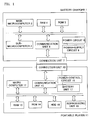
- FIG. 1 is a block diagram illustrating a battery charger 1 according a preferred embodiment of the present invention and a portable player (electronic device, content reproducing device) 11.
- the battery charger 1 charges a battery unit 17 of the portable player 11 by supplying a power-supply voltage to the portable player 11.
- the battery charger 1 mainly includes a main microcomputer 2, a sub-microcomputer 3, RAM 4, a ROM 5, a communication unit 6, a connection unit 7, a power circuit 8, and a power-supply circuit 9.
- the state discriminant apparatus of the present invention includes the main microcomputer (first control unit) 2 and the sub-microcomputer (second control unit) 3.
- the main microcomputer 2 controls each unit of the battery charger 1.
- the main microcomputer 2 develops and executes a program of the main microcomputer 2 stored in the ROM 5 on the RAM 4, thereby performing each process described below.
- the main microcomputer 2 controls an operating state of the sub-microcomputer 3. That is, the main microcomputer 2 transmits to the sub-microcomputer 3 an instruction for making a transition to a normal state or an instruction for making a transition to a low-power consumption state.
- the main microcomputer 2 also transmits an instruction for confirming a charging state of the portable player 11 to the sub-microcomputer 3.
- the normal state and the low-power consumption state exist in the operating state.
- the normal state is a state in which the main microcomputer 2 or the sub-microcomputer 3 can perform the operation, for example, a state in which an oscillation circuit (not illustrated) supplies a clock to a main circuit in the microcomputer.
- the low-power consumption state is a state in which the main microcomputer 2 or the sub-microcomputer 3 stops the operation to reduce power consumption lower than that of the normal state.
- the low-power consumption state is a state in which the oscillation circuit (not illustrated) does not supply the clock to the main circuit in the microcomputer.
- the main microcomputer 2 performs an intermittent operation in which the normal state and the low-power consumption state are repeated. Particularly, although the main microcomputer 2 is usually in the low-power consumption state during the charging of the portable player 11, the main microcomputer 2 makes the transition from the low-power consumption state to the normal state every predetermined time (for example, 10 seconds), and the main microcomputer 2 provides an instruction to confirm the charging state of the portable player 11 to the sub-microcomputer 3. The main microcomputer 2 then receives charging state information on the portable player 11 from the sub-microcomputer 3, and returns to the low-power consumption state when the portable player 11 is still being charged. Then the process is repeated after the predetermined time is elapsed again.
- predetermined time for example, 10 seconds
- the main microcomputer 2 makes the transition to the low-power consumption state after transmitting the instruction for making the transition to the low-power consumption state to the sub-microcomputer 3.
- the main microcomputer 2 is mostly in the low-power consumption state during the charging of the portable player 11, and thereby the power consumption can be reduced.
- the main microcomputer 2 monitors whether a connection unit 20 is connected to the connection unit 7 of the battery charger 1. When detecting that the connection unit 20 is connected to the connection unit 7 of the battery charger 1, the main microcomputer 2 controls the power-supply circuit 9 and the power circuit 8 such that a charging voltage is supplied to the portable player 11. When detecting that the portable player 11 has completed charging, the main microcomputer 2 controls the power-supply circuit 9 and the power circuit 8 such that the charging voltage is not supplied to the portable player 11.
- the sub-microcomputer 3 conducts communication with a microcomputer 12 of the portable player 11. Particularly, when receiving the instruction for confirming the charging state of the portable player 11 from the main microcomputer 2, the sub-microcomputer 3 inquires of the microcomputer 12 of the portable player 11 about the charging state (during charging or completion of charging). The sub-microcomputer 3 sends back the charging state information to the main microcomputer 2 when receiving the charging state information from the microcomputer 12 of the portable player 11. That is, during the charging of the portable player 11, since the main microcomputer 2 transmits the instruction for confirming the charging state every predetermined time, the sub-microcomputer 3 inquires of the microcomputer 12 of the portable player 11 about the charging state information in each case, and the sub-microcomputer sends back the charging state information to the main microcomputer 2.
- the sub-microcomputer 3 cannot change the operating state by itself, but changes the operating state in response to the instruction from the main microcomputer 2. That is, when receiving the instruction for making the transition to the low-power consumption state from the main microcomputer 2, the sub-microcomputer 3 makes the transition from the normal state to the low-power consumption state in response to the instruction. Similarly, when receiving the instruction for making the transition to the normal state from the main microcomputer 2, the sub-microcomputer 3 makes the transition from the low-power consumption state to the normal state in response to the instruction.
- the main microcomputer 2 does not transmit the instruction for making the transition to the low-power consumption state. Accordingly, the sub-microcomputer 3 maintains the normal state during the charging of the portable player 11.
- the main microcomputer 2 transmits the instruction for making the transition to the low-power consumption state. Accordingly, the sub-microcomputer 3 makes the transition to the low-power consumption state after the portable player 11 has completed charging.
- the communication unit 6 is an interface that conducts communication with the communication unit 15 of the portable player 11.
- the communication unit 6 transmits the instruction and information from the sub-microcomputer 3 to the communication unit 15 of the portable player 11, and supplies the instruction and information from the microcomputer 12 of the portable player 11 to the sub-microcomputer 3.
- connection unit 7 is a connector that connects the battery charger 1 and the connection unit 20 of the portable player 11.
- the connection unit 7 transmits and receives a control signal between the sub-microcomputer 3 and the microcomputer 12 to and from the connection unit 20.
- the connection unit 7 supplies the charging voltage produced by the power circuit 8 to the connection unit 20.
- the power circuit 8 produces the charging voltage from a commercial alternating-current power-supply voltage and supplies the charging voltage to the power-supply circuit 9.
- the power-supply circuit 9 supplies the charging voltage from the power circuit 8 to the portable player 11 through the connection unit 7.
- a reproducing unit 19 reads and reproduces contents (such as music data and video data) stored in an HDD 18.
- the portable player 11 mainly includes the microcomputer 12, the RAM 13, the ROM 14, a communication unit 15, a power control circuit 16, the battery unit 17, the HDD 18, and the reproducing unit 19.
- the microcomputer 12 controls each unit of the portable player 11, and the microcomputer 12 develops and executes a program stored in the ROM 14 on the RAM 13, thereby performing each process.
- the microcomputer 12 always confirms the charging state (during charging or completion of charging) of the battery unit 17.
- the microcomputer 12 sends back the charging state information (during charging or completion of charging) to the sub-microcomputer 3.
- the communication unit 15 is an interface that conducts communication with the communication unit 6 of the battery charger 1.
- the communication unit 15 transmits the instruction and information from the microcomputer 12 to the communication unit 6 of the battery charger 1, or transmits the instruction and information from the sub-microcomputer 3 of the battery charger 1 to the microcomputer 12.
- the power control circuit 16 controls the power-supply voltage at the battery unit 17.
- the power control circuit 16 supplies the charging voltage, supplied from the battery charger 1, to battery unit 17 to charge the battery unit 17.
- the power control circuit 16 supplies the voltage charged in the battery unit 17 to each unit of the portable player 11.
- the battery unit 17 charges the voltage in order to drive the portable player 11.
- connection unit 20 is a connector that connects the portable player 11 and the connection unit 7 of the battery charger 1.
- the connection unit 20 transmits and receives the control signal between the sub-microcomputer 3 and the microcomputer 12 to and from the connection unit 7.
- the connection unit 20 supplies the charging voltage produced by the power circuit 8 from the connection unit 7.
- the main microcomputer 2 and the sub-microcomputer3areinthelow-powerconsumptionstate (S1 and S31).
- a user connects the portable player 11 to the battery charger 1 to charge the portable player 11.
- the main microcomputer 2 detects that the connection unit 20 of the portable player 11 is connected to the connection unit 7 (S2).
- a connection detecting circuit (not illustrated) feeds an interruption signal into the main microcomputer 2.
- the main microcomputer 2 makes the transition from the low-power consumption state to the normal state (S3).
- the main microcomputer 2 controls the power circuit 8 and the power-supply circuit 9 such that the charging voltage is supplied to the battery unit 17 of the portable player 11. Therefore, the portable player 11 starts to charge the battery unit 17.
- the microcomputer 12 always monitors the charging state (during charging or completion of charging) of the battery unit 17.
- the main microcomputer 2 transmits the instruction for making the transition to the normal state to the sub-microcomputer 3 (S4).
- the sub-microcomputer 3 makes the transition from the low-power consumption state to the normal state (S32). Then the sub-microcomputer 3 maintains the normal state until the sub-microcomputer 3 receives the instruction for making the transition to the low-power consumption state from the main microcomputer 2.
- the main microcomputer 2 transmits the instruction for confirming the charging state of the portable player 11 to the sub-microcomputer 3 (S5).
- the sub-microcomputer 3 transmits the inquiry about the charging state to the microcomputer 12 of the portable player 11 (S33).
- the microcomputer 12 sends back the charging state information (during charging or completion of charging) to the sub-microcomputer 3 (S51).
- the sub-microcomputer 3 sends back the charging state information to the main microcomputer 2 (S34).
- the main microcomputer 2 determines whether the portable player 11 has completed charging based on the charging state information (S6). When the portable player 11 is still being charged (NO in S6), the main microcomputer 2 makes the transition from the normal state to the low-power consumption state (S7). When making the transition from the normal state to the low-power consumption state, the main microcomputer 2 starts counting of a timer using a built-in timer circuit, and the main microcomputer 2 determines whether a predetermined time (for example, 10 seconds) has elapsed since the main microcomputer 2 made the transition to low-power consumption state (for example, 10 seconds) (S8).
- a predetermined time for example, 10 seconds
- the main microcomputer 2 in the low-power consumption state, the main microcomputer 2 cannot control each unit of the battery charger 1, but can count the predetermined time. Since the main microcomputer 2 is in the low-power consumption state while the predetermined time elapses, the power consumption of the main microcomputer 2 can be reduced during the charging of the portable player 11.
- the main microcomputer 2 makes the transition from the low-power consumption state to the normal state (S9).
- the flow returns to S5, the main microcomputer 2 repeats the processes in S5 to S9 such that the instruction for confirming the charging state of the portable player 11 is transmitted to the sub-microcomputer 3.
- the main microcomputer 2 Since it is continuously determined as NO in S6 during the charging of the portable player 11, the main microcomputer 2 is usually in the low-power consumption state in which the power consumption is reduced, but the main microcomputer 2 continues to perform the following operation. That is, the main microcomputer 2 makes the transition from the low-power consumption state to the normal state every predetermined time (for example, 10 seconds), confirms the charging state of the portable player 11 through the sub-microcomputer 3, and returns to the low-power consumption state.
- predetermined time for example, 10 seconds
- the main microcomputer 2 transmits the instruction for making the transition to the low-power consumption state to the sub-microcomputer 3 (S10).
- the main microcomputer 2 controls the power circuit 8 and the power-supply circuit 9 such that the charging voltage is not supplied to the portable player 11.
- the sub-microcomputer 3 makes the transition from the normal state to the low-power consumption state (S35).
- the main microcomputer 2 also makes the transition from the normal state to the low-power consumption state (S11). Accordingly, after the portable player 11 has completed charging, the main microcomputer 2 and the sub-microcomputer 3 make the transition to the low-power consumption state, and maintain the low-power consumption state, thereby the power consumption can be reduced.
- the main microcomputer 2 is usually in the low-power consumption state, and the main microcomputer 2 becomes the normal state only when the main microcomputer 2 confirms the charging state of the portable player 11. Therefore, the power consumption of the main microcomputer 2 can be reduced.
- the portable player 11 may send currently charged amount of the portable player 11 instead of the charging state.
- the main microcomputer 2 may determine the charging state based on the currently charged amount of the portable player 11. In this case, the main microcomputer 2 determines that the charging state of the portable player 11 is completion of charging if the currently charged amount of the portable player 11 is maximum value, and determines that the charging state of the portable player 11 is during charging if the currently charged amount of the portable player 11 is not maximum value.
- a predetermined time since the main microcomputer 2 has made the transition to the low-power consumption state in S7 of FIG. 2 until the main microcomputer 2 makes the transition to the normal state to confirm the charging state of the portable player 11 is determined according to a charging information relating to the currently charged amount of the portable player 11 (for example, a charging rate).
- the charging rate means the currently-charged amount with respect to a maximum charging capacity of the battery unit 7, that is, 100 ⁇ (currently charged amount) / (maximum charging capacity) (%).
- the microcomputer 12 of the portable player 11 always computes the charging rate, and both the charging rate and the charging state information are sent back to the sub-microcomputer 3. Or, the microcomputer 12 of the portable player 11 sends the currently charged amount and the maximum charging capacity to the battery charger 1 and the main microcomputer 2 computes the charging rate.
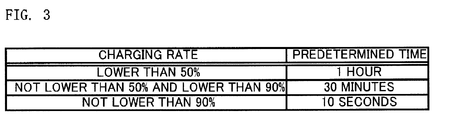
- a predetermined time table of FIG. 3 is stored in the ROM 5.
- the predetermined time with respect to the charging rate is registered in advance in the predetermined time table. Referring to FIG. 3 , the predetermined time is 1 hour when the charging rate is lower than 50%, the predetermined time is 30 minutes when the charging rate is not lower than 50% and is lower than 90%, the predetermined time is 10 seconds when the charging rate is not lower than 90%. That is, as the charging rate is increased, the predetermined time is shortened, and the main microcomputer 2 more frequently makes the transition from the low-power consumption state to normal state to confirm the charging state of the portable player 11. That is, for the high charging rate, the main microcomputer 2 needs to frequently confirm the charging state since the time required for completing the charging of the portable player 11 is short.
- the main microcomputer 2 wastefully needs to make the transition to the normal state when the charging state is frequently confirmed, and the power consumption of the main microcomputer 2 is increased.
- a conditional expression of the predetermined time table may be included in the program of the main microcomputer 2.
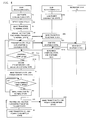
- FIG. 4 is a flowchart illustrating the process of the present embodiment.
- the same process as that of FIG. 2 is designated by the same reference numeral, and the description thereof will not be given.
- the main microcomputer 2 transmits the instruction for confirming the charging state of the portable player 11 to the sub-microcomputer 3.
- the sub-microcomputer 3 transmits the inquiry about the charging state to the microcomputer 12 of the portable player 11 (S33).
- the microcomputer 12 sends back the charging state information (during charging or completion of charging) and the charging rate to the sub-microcomputer 3 (S151).
- the sub-microcomputer 3 sends back the charging state information and the charging rate to the main microcomputer 2 (S134).
- the main microcomputer 2 determines whether the portable player 11 has completed charging based on the charging state information (S6). When the portable player 11 is still being charged (NO in S6), the main microcomputer 2 decides the predetermined time based on the received charging rate (S101). Particularly, for example, the main microcomputer 2 refers to the predetermined time table of FIG. 3 , and the main microcomputer 2 decides that the predetermined time is 1 hour when the charging rate is lower than 50%, 30 minutes when the charging rate is not lower than 50% and is lower than 90%, and 10 seconds when the charging rate is not lower than 90%.
- the main microcomputer 2 makes the transition from the normal state to the low-power consumption state (S7).
- the main microcomputer 2 starts the count of the timer using the built-in timer circuit, and the main microcomputer 2 determines whether the predetermined time decided in S101 has elapsed since the main microcomputer 2 has made the transition to the low-power consumption state (S8).
- the main microcomputer 2 makes the transition from the low-power consumption state to the normal state (S9). Then the flow returns to S5.
- the subsequent processes are identical to the processes of FIG. 2 .
- the main microcomputer 2 decides the predetermined time until the main microcomputer makes the transition from the low-power consumption state to the normal state and confirms the charging state of the portable player 11. That is, for the high charging rate of the portable player 11, since the main microcomputer 2 more frequently confirms the charging state of the portable player 11, the increase of the power consumption can be prevented.
- the main microcomputer 2 cannot recognize the completion of the charging of the portable player 11 although the portable player 11 has completed charging, the sub-microcomputer 3 wastefully maintains the normal state for a long period of time to increase the power consumption.
- the time the main microcomputer 2 maintains the low-power consumption state can be lengthened to further reduce the power consumption.
- the present invention is not limited thereto.
- the predetermined time may be decided based on a remaining time to the completion of the charging.
- the remaining time to the completion of the charging is one of the charging information relating to the currently charged amount of the portable player 11.
- the predetermined time may be decided based on the currently charged amount of the portable player 11.
- the predetermined time is set shorter with decreasing remaining time to the completion of the charging.
- the present invention may be provided in a form of a program for causing the main microcomputer 2 or the sub-microcomputer 3 to execute the operation of the main microcomputer 2 or the sub-microcomputer 3 or a recording medium in which the program is recorded.
- the battery charger 1 may be incorporated in an audio apparatus such as an AV amplifier.
- the electronic device charged by the battery charger 1 may be a mobile telephone, a digital camera, or a portable game machine.
Landscapes
- Engineering & Computer Science (AREA)
- Theoretical Computer Science (AREA)
- Physics & Mathematics (AREA)
- General Engineering & Computer Science (AREA)
- General Physics & Mathematics (AREA)
- Direct Current Feeding And Distribution (AREA)
- Power Sources (AREA)
- Charge And Discharge Circuits For Batteries Or The Like (AREA)
Applications Claiming Priority (2)
| Application Number | Priority Date | Filing Date | Title |
|---|---|---|---|
| JP2009132628 | 2009-06-02 | ||
| JP2010089713A JP4756402B2 (ja) | 2009-06-02 | 2010-04-08 | 状態判別装置 |
Publications (2)
| Publication Number | Publication Date |
|---|---|
| EP2259165A2 true EP2259165A2 (de) | 2010-12-08 |
| EP2259165A3 EP2259165A3 (de) | 2012-08-29 |
Family
ID=42173056
Family Applications (1)
| Application Number | Title | Priority Date | Filing Date |
|---|---|---|---|
| EP10160071A Withdrawn EP2259165A3 (de) | 2009-06-02 | 2010-04-15 | Statusdikriminierende Vorrichtung und Verfahren |
Country Status (2)
| Country | Link |
|---|---|
| EP (1) | EP2259165A3 (de) |
| JP (1) | JP4756402B2 (de) |
Cited By (1)
| Publication number | Priority date | Publication date | Assignee | Title |
|---|---|---|---|---|
| US20240087385A1 (en) * | 2020-12-29 | 2024-03-14 | Essence Security International (E.S.I.) Ltd. | A Padlock |
Families Citing this family (1)
| Publication number | Priority date | Publication date | Assignee | Title |
|---|---|---|---|---|
| JP6835011B2 (ja) * | 2018-02-27 | 2021-02-24 | 京セラドキュメントソリューションズ株式会社 | Usb給電装置 |
Family Cites Families (10)
| Publication number | Priority date | Publication date | Assignee | Title |
|---|---|---|---|---|
| JPH06121466A (ja) * | 1992-10-05 | 1994-04-28 | Nippon Electric Ind Co Ltd | 被充電物の充電方法 |
| JPH1098837A (ja) * | 1996-09-20 | 1998-04-14 | Toshiba Corp | 二次電池の満充電検知方法、及び充電制御装置 |
| JP3757511B2 (ja) * | 1997-01-20 | 2006-03-22 | コニカミノルタホールディングス株式会社 | ディジタルスチルカメラ |
| JP4038860B2 (ja) * | 1998-02-16 | 2008-01-30 | ソニー株式会社 | 充電装置 |
| JP3792066B2 (ja) * | 1999-03-31 | 2006-06-28 | シャープ株式会社 | 低消費電力周辺機器 |
| JP2002351436A (ja) * | 2001-05-25 | 2002-12-06 | Sony Corp | ディスプレイ装置及びディスプレイ装置の低消費電力モードへの遷移と復帰方法 |
| JP2005292873A (ja) * | 2004-03-31 | 2005-10-20 | Hitachi Ltd | 携帯情報端末装置 |
| US7430679B2 (en) * | 2005-08-31 | 2008-09-30 | Apple Inc. | Charging of mobile devices |
| JP4732082B2 (ja) * | 2005-09-07 | 2011-07-27 | シャープ株式会社 | 放送受信端末及びその制御方法 |
| JP4808036B2 (ja) * | 2006-02-15 | 2011-11-02 | 富士通株式会社 | 電子機器 |
-
2010
- 2010-04-08 JP JP2010089713A patent/JP4756402B2/ja not_active Expired - Fee Related
- 2010-04-15 EP EP10160071A patent/EP2259165A3/de not_active Withdrawn
Non-Patent Citations (1)
| Title |
|---|
| None |
Cited By (2)
| Publication number | Priority date | Publication date | Assignee | Title |
|---|---|---|---|---|
| US20240087385A1 (en) * | 2020-12-29 | 2024-03-14 | Essence Security International (E.S.I.) Ltd. | A Padlock |
| US12444256B2 (en) * | 2020-12-29 | 2025-10-14 | Essence Security International (E.S.1.) Ltd. | Padlock |
Also Published As
| Publication number | Publication date |
|---|---|
| EP2259165A3 (de) | 2012-08-29 |
| JP2011014126A (ja) | 2011-01-20 |
| JP4756402B2 (ja) | 2011-08-24 |
Similar Documents
| Publication | Publication Date | Title |
|---|---|---|
| JP3764338B2 (ja) | バッテリを認識する方法及び装置 | |
| US9099883B2 (en) | System and method for controlling charging of battery of portable terminal | |
| US20130134923A1 (en) | Apparatus, and associated method, for providing charging energy to recharge a portable power supply | |
| US20140306657A1 (en) | Method and apparatus for optimizing standby power consumption and providing user indications in wpc based wireless charging system | |
| US9438058B2 (en) | Electronic device | |
| JP5433672B2 (ja) | 電子機器及び給電方法 | |
| US20080242369A1 (en) | Portable electronic apparatus | |
| KR20130105891A (ko) | 휴대용 전자 디바이스 및 그것에서 사용되는 재충전가능한 배터리에 대한 전력을 복원하기 위한 방법 | |
| EP3771961B1 (de) | Elektronische vorrichtung, verfahren, programm und speichermedium | |
| CA2796686C (en) | Apparatus, and associated method, for providing charging energy to recharge a portable power supply | |
| CN108964182A (zh) | 反向充电设备、反向充电电流的调节方法及装置 | |
| KR20160015613A (ko) | 충전 제어 방법 및 이를 지원하는 전자 장치 | |
| US20080015807A1 (en) | Transferring data in a portable electronic device | |
| KR101835007B1 (ko) | 휴대용 단말기에서 충전 전류를 제어하기 위한 장치 및 방법 | |
| CN103810792B (zh) | 处理电源状态的方法和支持该方法的终端 | |
| JP2010081790A (ja) | 電子機器 | |
| EP2259165A2 (de) | Statusdikriminierende Vorrichtung und Verfahren | |
| US12242588B2 (en) | Electronic device and method | |
| CN107515667A (zh) | 节电方法及智能眼镜 | |
| JP2020188626A (ja) | 電子機器および制御方法 | |
| JP2008118285A (ja) | 携帯端末及び充電制御方法 | |
| JP2006011865A (ja) | 携帯電話端末電源供給システム | |
| CN114503390A (zh) | 用于控制对电子装置的电池的充电的方法及其电子装置 | |
| US20120084581A1 (en) | Power supply control apparatus, electric device, power supply control system, and power supply control method and program | |
| JP2002314711A (ja) | 携帯式小型電気機器 |
Legal Events
| Date | Code | Title | Description |
|---|---|---|---|
| PUAI | Public reference made under article 153(3) epc to a published international application that has entered the european phase |
Free format text: ORIGINAL CODE: 0009012 |
|
| AK | Designated contracting states |
Kind code of ref document: A2 Designated state(s): AT BE BG CH CY CZ DE DK EE ES FI FR GB GR HR HU IE IS IT LI LT LU LV MC MK MT NL NO PL PT RO SE SI SK SM TR |
|
| AX | Request for extension of the european patent |
Extension state: AL BA ME RS |
|
| RAP1 | Party data changed (applicant data changed or rights of an application transferred) |
Owner name: ONKYO CORPORATION |
|
| RAP1 | Party data changed (applicant data changed or rights of an application transferred) |
Owner name: ONKYO CORPORATION |
|
| PUAL | Search report despatched |
Free format text: ORIGINAL CODE: 0009013 |
|
| AK | Designated contracting states |
Kind code of ref document: A3 Designated state(s): AT BE BG CH CY CZ DE DK EE ES FI FR GB GR HR HU IE IS IT LI LT LU LV MC MK MT NL NO PL PT RO SE SI SK SM TR |
|
| AX | Request for extension of the european patent |
Extension state: AL BA ME RS |
|
| RIC1 | Information provided on ipc code assigned before grant |
Ipc: H02J 7/00 20060101ALI20120725BHEP Ipc: G06F 1/32 20060101AFI20120725BHEP |
|
| STAA | Information on the status of an ep patent application or granted ep patent |
Free format text: STATUS: THE APPLICATION IS DEEMED TO BE WITHDRAWN |
|
| 18D | Application deemed to be withdrawn |
Effective date: 20130301 |