EP2259409A2 - Elektrische rotierende Maschine und Herstellungsverfahren dafür - Google Patents
Elektrische rotierende Maschine und Herstellungsverfahren dafür Download PDFInfo
- Publication number
- EP2259409A2 EP2259409A2 EP10164655A EP10164655A EP2259409A2 EP 2259409 A2 EP2259409 A2 EP 2259409A2 EP 10164655 A EP10164655 A EP 10164655A EP 10164655 A EP10164655 A EP 10164655A EP 2259409 A2 EP2259409 A2 EP 2259409A2
- Authority
- EP
- European Patent Office
- Prior art keywords
- rotor
- rotor core
- spider
- electric machine
- rotating electric
- Prior art date
- Legal status (The legal status is an assumption and is not a legal conclusion. Google has not performed a legal analysis and makes no representation as to the accuracy of the status listed.)
- Granted
Links
Images




Classifications
-
- H—ELECTRICITY
- H02—GENERATION; CONVERSION OR DISTRIBUTION OF ELECTRIC POWER
- H02K—DYNAMO-ELECTRIC MACHINES
- H02K1/00—Details of the magnetic circuit
- H02K1/06—Details of the magnetic circuit characterised by the shape, form or construction
- H02K1/22—Rotating parts of the magnetic circuit
- H02K1/28—Means for mounting or fastening rotating magnetic parts on to, or to, the rotor structures
- H02K1/30—Means for mounting or fastening rotating magnetic parts on to, or to, the rotor structures using intermediate parts, e.g. spiders
-
- H—ELECTRICITY
- H02—GENERATION; CONVERSION OR DISTRIBUTION OF ELECTRIC POWER
- H02K—DYNAMO-ELECTRIC MACHINES
- H02K7/00—Arrangements for handling mechanical energy structurally associated with dynamo-electric machines, e.g. structural association with mechanical driving motors or auxiliary dynamo-electric machines
- H02K7/04—Balancing means
-
- Y—GENERAL TAGGING OF NEW TECHNOLOGICAL DEVELOPMENTS; GENERAL TAGGING OF CROSS-SECTIONAL TECHNOLOGIES SPANNING OVER SEVERAL SECTIONS OF THE IPC; TECHNICAL SUBJECTS COVERED BY FORMER USPC CROSS-REFERENCE ART COLLECTIONS [XRACs] AND DIGESTS
- Y10—TECHNICAL SUBJECTS COVERED BY FORMER USPC
- Y10T—TECHNICAL SUBJECTS COVERED BY FORMER US CLASSIFICATION
- Y10T29/00—Metal working
- Y10T29/49—Method of mechanical manufacture
- Y10T29/49002—Electrical device making
- Y10T29/49009—Dynamoelectric machine
- Y10T29/49012—Rotor
Definitions
- the present invention relates to a rotating electric machine and a manufacturing method thereof.
- steel plate material of magnetic steel plates used for a rotor of a rotating electric machine is roll formed. With the process of manufacture of rolling, deviations are unavoidable in widthwise thickness of the steel plate material. In the event that such steel plate material is punched so as to manufacture rotor plates used for laminated bodies such as rotor cores, deviations in thickness having a certain directionality according to rolling direction remain on each of the rotor plates.
- the present invention intends to provide a rotating electric machine and a manufacturing method thereof with high productivity which do not require complex equipment and extra processes.
- a rotating electric machine comprises: a stator and a rotor that is rotatably provided through a rotary gap with respect to the stator, wherein the rotor includes a rotor core in which rotor plates punched from roll formed magnetic steel plate are laminated, and a spider that retains the rotor core; the rotor plates and the rotor core include a plurality of keys arranged in their inner circumference contacting with the spider; the spider includes a plurality of keyways arranged in its outer circumference contacting with the rotor; a plurality of keys of the rotor core and a plurality of keyways of the spider are formed in such a manner that they fit with each other; and/or the plurality of keys of the rotor core and the plurality of keyways of the spider fit in a combination that renders a weight imbalance of the rotor core due to lamination of the rotor plates and a weight imbalance of the spider cancel each other.
- At least one of the plurality of keyways of the spider is formed as a small width keyway which has a smaller width than other keyways, and among the plurality of keys of the rotor core, a rotor core minimum mass key, which preferably shows that a mass of the rotor core in a direction in which the rotor minimum mass key exists is minimum, is preferably fitted into the small width keyway.
- a rotor plate minimum mass key in position of the rotor core minimum mass key, among the plurality of keys of the rotor plates, a rotor plate minimum mass key, a rotor plate minimum mass key, which is preferably a key indicating a part of the rotor plate where the rotor plate have less thickness than other part, is preferably piled up.
- an identification marking is provided in a vicinity of the rotor core minimum mass key.
- the rotor core is fitted into the spider by shrink-fitting, whereby the rotor core is preferably fitted into the spider in such a manner that the keys and the keyways are fitted together.
- magnet insertion holes are formed in the rotor core, and magnets are preferably respectively inserted into the magnet insertion holes.
- a shaft is fitted into the spider and as well a ring plate is fitted into the spider, and a balance adjustment hole, through which a weight imbalance that is left behind after weight imbalance cancellation by a combination of the rotor core and the spider is complementary cancelled, is preferably formed in the ring plate.
- the rotor core is provided with lamination of the rotor plates, wherein the rotor plates are rotary laminated as needed, so that a part of a rotor core in a position of the rotor core minimum mass key is smaller in mass than any other part located in positions of other keys.
- a shaft is preferably fitted into the spider and as well a ring plate is preferably fitted into the spider, and a balance adjustment hole, through which a weight imbalance that is left behind after weight imbalance cancellation by a combination of the rotor core and the spider is complementary cancelled, is preferably formed in the ring plate.
- the rotor core is provided by rotationally stacking an odd number of blocks, wherein in each block a rotor plate minimum mass key, which is preferably a key indicating a part of the rotor plate where the rotor plate have less thickness than other part, is preferably piled up.
- a rotating electric machine in a rotating electric machine according to claim 1, it is preferred that a rotating electric machine is an induction motor, wherein holes into which conductors are inserted are preferably formed in the rotor core and aluminium or copper is preferably inserted into the holes by die-casting.
- the keyways are formed into a depth in which a weight imbalance due to lamination of the rotor plates and a weight imbalance of the spider preferably cancel each other.
- a manufacturing method of a rotating electric machine comprises: a stator and a rotor that is rotatably provided through a rotary gap with respect to the stator, wherein the rotor includes a rotor core in which rotor plates punched from roll formed magnetic steel plate are laminated, and a spider that retains the rotor core, wherein the rotor core includes a plurality of keys arranged in their inner circumference contacting with the spider, wherein the spider includes a plurality of keyways arranged in its outer circumference contacting with the rotor, and wherein a plurality of keys of the rotor core and the plurality of keyways of the spider are formed in such a manner that they fit with each other; wherein a roll formed magnetic steel plate is punched so that one of the plurality of keys is arranged at 90 degrees to rolling direction of the steel plate; and/or the keys of the rotor core and the keyways of the spider are fitted in a combination that
- At least one of the plurality of keyways of the spider is formed as a small width keyway which has a smaller width than other keyways; and the plurality of keys of the rotor core and the plurality of keyways of the spider are preferably fitted so that among keys of the plurality of the rotor core, a rotor core minimum mass key, which preferably shows a minimum mass of the rotor core in a direction in which the rotor minimum mass key exists, preferably fits into the small width keyway.
- the rotor core is formed by laminating the rotor plates, in such a manner that position of a rotor minimum mass key among a plurality of keys in each of the rotor plates, which is preferably positioned in a thinner part than other part in each of the rotor plates, is preferably piled up.
- the spider is mounted to a shaft, a ring plate is preferably inserted into the spider, and a balance adjustment hole, through which a weight imbalance that is left behind to be cancelled by a combination of the rotor core and the spider is complemented, is preferably formed in the ring plate.
- a rotating electric machine and a manufacturing method thereof with high productivity that do not require complex equipment and extra processes can be provided.
- the balance of a rotor is adjusted by removing or providing mass in the final production process after all the rotor components are assembled. Accordingly, in the event that an initial imbalance is large in a state where the rotor components are assembled, the removed or provided mass for adjustment becomes large, and, in an extreme case, can not be adjusted to design requirements. Therefore, reduction in the initial imbalance in a state of rotor assembly leads to reduction in man-hours for balance adjustment.
- the initial imbalance of the rotor depends on the combined value of the imbalance in each of the components and the imbalance that occurs due to assembly gap between the components. A major part of the initial imbalance of the rotor is accounted for by the imbalance due to accumulated deviation in thickness of the laminated steel plates in the rotor core.
- steel plate material of magnetic steel plates used for rotors of rotating electric machines is roll formed, and tiny deviations occur in widthwise thickness of the steel plate material while it is rolled. It goes beyond the limits of the current technology to completely eliminate such deviations. Therefore, in the event that such steel plate material is punched so as to manufacture rotor plates used for a laminated body such as a rotor core, deviations in thickness having a certain directionality as to rolling direction remain on each rotor plate.
- the laminated rotor plates to which rotary lamination is not applied which does not require complex structure punching equipment, is used as a rotor core so as to provide the rotor of the rotating electric machine that resolves the issue of the mass imbalance.
- the laminated rotor plates in which rotary lamination is not applied is used as a rotor core so as to assemble the rotor so that the mass imbalance due to the accumulated deviation in plate thickness of the rotor core and the mass imbalance due to the difference between the keyway widths of the shaft or the spider cancel each other.
- the rotor in which rotary lamination of the rotor plates is not applied has the mass imbalance due to the accumulated deviation in plate thickness i.e., the initial imbalance as a rotating body.
- one of the keyways is defined as the reference, and its width dimension is set smaller than that of any of the others.
- the width dimension of the reference keyway is set with a small clearance so that the reference keyway tightly fits the key of the corresponding rotor core, whilst the width dimensions of the other keyways are set with a sufficient clearance that can absorb component dimension tolerance.
- the shaft or the spider has the initial imbalance depending upon the difference in width dimension of the keyways.
- the initial imbalance becomes greater as the axial dimension becomes greater and as the diameter of the keyway position becomes greater.
- the rotors are assembled so that the initial imbalance of the rotor core and the initial imbalance of the shaft or the spider cancel each other, thereby improving the overall initial imbalance.
- the initial imbalance of the rotor in a state where the components are now assembled can be reduced, and, in the following process of balance adjustment, the removed or provided mass that is required to assure the necessary balance accuracy can be reduced. In other words, the man-hours required for the balance adjustment can be reduced, thereby contributing to reduction in cost.
- the balance accuracy that can be modified per adjustment is determined by the removed or provided mass. This is because the accuracy after the balance adjustment becomes the accuracy that the error in imbalance amount measurement and the error in the removed or provided mass are combined.
- the initial imbalance can be reduced, and adjustment accuracy per one balance adjustment process can be improved. In other words, reduction in vibrations and noise can be achieved as a rotating electric machine.
- the complex structure of the rotary lamination to cancel the deviation in lamination thickness can be reduced and the equipment construction can be simplified, thereby reducing the cost of investment in facilities.
- the capacity of the press machine can be reduced by shortening the whole length of the stage of punching, manufacturing is made possible using a smaller press machine.
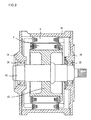
- FIG. 2 is an overall cross-section view of the rotating electric machine.
- a stator 3 is fixed to a housing 1c with fixing the stator core to the housing 1c by interference fitting, and a rotor 4 includes a spider 42 and a shaft 43, being rotatably supported by bearings 2a and 2b.
- the rotor 4 is supported to be rotatable against the stator 3 with small gap between the rotor and the stator.
- FIG. 3 shows how each plate of the rotor core is punched from magnetic steel plate.
- the magnetic steel plate a material, is manufactured by rolling, has a deviation in plate thickness at a right angle to the rolling direction of the steel plate shown in FIG. 3 , and is thinner towards one side 411a than the other side 411b.
- Each rotor plate of a rotor core having two key shapes 412 with the same shape in the inner circumference, and these two key shapes 412 are arranged at 90 degrees to the rolling direction of the magnetic steel plate shown in FIG. 3 , i.e., in the direction in which the deviation in plate thickness is maximized. In this way, the plates of a rotor core are punched in series.
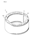
- the punched plates are stacked in the punching equipment, and are swaged as a predetermined total thickness has been reached, thus providing a rotor core 41 as presented in FIG. 4 .
- the rotor plates produced by punching are stacked so that the thinner parts of the rotor plates or the thicker parts of the rotor plates are piling up together.
- the greatest accumulated deviation in plate thickness of the material occurs in the direction of the two key shapes 412.
- the greatest deviation in lamination thickness i.e., mass imbalance occurs in the direction of the key shapes 412a and 412b in FIG. 4 .
- the position of the key shape 412a is thinner or lighter than the other positions, while the position of the key shape 412b is thicker or heavier than the other positions.
- the key such as the key shape 412a which is positioned in the lightest part of a rotor plate or of a rotor core represents a minimum mass key.
- the spider 42 includes keyways 421 and 422 on the outer circumference which is in contact with the rotor core, corresponding to the key shapes 412 of the rotor core.
- the width of the keyway 421 is set so that the keyway 421 tightly fits the key shape 412 of the rotor core, whilst the width of the keyway 422 is set so that the keyway 422 can absorb the tolerances of shape and position dimensions of the key shapes 412 of the rotor core and the tolerances of shape and the position dimensions the keyway 422 itself.
- the width of the keyway 421 becomes smaller than that of the keyway 422. It is to be noted that the depths of the both keyways are same.
- FIG. 6A shows the shape of the keyway 421 and FIG. 6B shows the shape of the keyway 422.
- a keyway width 4211 is smaller than a keyway width 4221.
- a direction identification 423 of the mass imbalance is provided on the side where the keyway position at which the mass is heavy, i.e., the keyway 421 side.
- the mark of a serial number of a component is denoted by the identification 423.
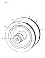
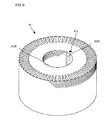
- FIG. 1 presents a perspective view of a state in which the rotor core 41, the spider 42, and the shaft 43 are assembled.
- the spider 42 is assembled to the shaft 43 by shrink fitting, and a ring plate 51 is inserted into the spider 42.
- the rotor core 41 is assembled to the spider 42 so that the identification marking 413 of the rotor core 41 and the identification 423 of the spider 42 match.
- the key of the light side of the mass of the rotor core 41 is fitted with the keyway of the heavy side of the mass of the spider 42. This results in achieving an effect that the mass imbalance of the rotor core 41 and that of the spider 42 cancel each other.
- a small initial imbalance amount enables an adjustment with higher balance accuracy, thereby reducing vibrations and noise as a rotating electric machine.
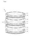
- FIG. 8 illustrates the structure of the rotor core 41 in which rotary stacking of blocks is applied.
- Each plate in a laminated block with a predetermined thickness is punched in the same manner as that in the embodiment 1, and each block is rotated by 180 degrees when the rotation is necessary for balancing, thus the rotor core being constructed with the stacked blocks.
- an identification marking is provided in the position of each block where the mass of each block is minimum, namely in the vicinity of the minimum mass key of the laminated rotor plate, indicating a minimum mass key of a block.
- the identification markings 413 of building blocks 41a, 41c, and 41e are in the same direction
- the identification markings 413 of constituent blocks 41b and 41d are arranged in the opposite direction thereof by rotating the constituent blocks 41b and 41d by 180 degrees, and thus the rotor core 41 is constructed.
- the effect of improving the initial imbalance of the rotor can be achieved in the similar manner as the embodiment 1.
- the lamination thickness of blocks and the number of blocks to be rotated by 180 degrees may be arranged so as to balance out the mass imbalance that the spider 42 has.
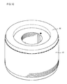
- FIG. 9 shows a perspective view of the rotor core 41 of the induction motor.
- a steel plate is punched so that the key shapes 412 are arranged at 90 degrees to the rolling direction of the magnetic steel plate, and laminated to a predetermined lamination thickness without applying rotary lamination. Then, a lamination thickness measurement is performed, and the identification marking 413 is provided on the key shape 412a position, in which lamination thickness is smaller.
- a temporary shaft is inserted and aluminium or copper is die-casted so as to form a conductor section 44 of a squirrel-cage rotor as shown in FIG. 10 .
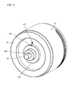
- FIG. 11 shows a perspective view of the rotor into which the shaft 43 is inserted.
- the shaft 43 which is inserted thereinto, is provided with keyways which correspond to the keys of the rotor core 41, and the width of the keyway 431 is set smaller than that of the keyway 432, thereby having a mass imbalance.
- the mass at the keyway 431 position is heavier than that at the keyway 432 position.
- the direction of the keyway 431 is identified using a groove 433 provided on the shaft 43.
- the rotor is constructed by inserting the shaft 43 so that the identification marking 413 of the rotor core 41 and an identification 433 of the shaft 43 match. In the similar manner as the embodiment 1, this allows the imbalance amounts of the rotor core 41 and the shaft 43 to be cancelled each other, thereby improving the initial imbalance and achieving the same effect as that in the embodiment 1.
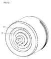
- the ring plate 52 is assembled by shrink fitting for avoiding slipping off of the shaft in the axial direction, and then, a balance adjustment is conducted.
- the balance adjustment is conducted by boring the hole 415 in the rotor core 41 to a specified balance accuracy.
- the present embodiment is applied to the shaft or the spider of the rotor of the rotating electric machine including a plurality of keyways so as to resolve the initial imbalance due to the difference in keyway width described above.
- the depths of the keyways may be set corresponding to the difference in the widths of the keyways of the shaft or the spider, thereby resolving the initial imbalance.
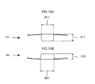
- FIG. 13A and FIG.13B The shapes of the keyways 421 and 422 when the present embodiment is applied to the spider 42 shown in FIG. 6A and FIG.6B are shown in FIG. 13A and FIG.13B .
- a width 4211 of the keyway 421(see FIG.13A ) is set smaller than a width 4221 of the keyway 422(see FIG.13B ), and a depth 4212 of the keyway 421 is set greater than a depth 4222 of the keyway 422.
- the amount of material of the spider 42 to be removed for the keyway 421 and the amount for the keyway 422 become equal, thereby resolving the initial imbalance of the spider 42.
- the rotary lamination may be applied to the rotor core production method, where each rotor plate is rotated as needed.
- the rotary lamination may be carried out by alternating the direction of each rotor plate, or by rotating the directions of rotor plates for every couple of rotor plates, or rotating each rotor plate as needed.
- the rotary lamination may be applied to the above described production method of a block, so as to rotate the direction of each rotor plate as needed.
- the rotary lamination may be carried out by alternating the direction of each rotor plate, or by rotating the directions of rotor plates for every couple of rotor plates, or rotating each rotor plate as needed.
- the rotor core or the block thus produced by rotary lamination has already a largely reduced mass imbalance. However, there is still remaining some mass imbalance between the two keys of the rotor core.
- the mass the rotor is less in the position where more minimum mass keys of rotor plates are stacked.
- the mass imbalance is further reduced, in which case the minimum mass key may be determined by measuring the weights of the positions of two keys.
- the mass imbalance is adjusted by arranging a balance adjustment hole 521 in the ring plate 52.
Landscapes
- Engineering & Computer Science (AREA)
- Power Engineering (AREA)
- Manufacture Of Motors, Generators (AREA)
- Iron Core Of Rotating Electric Machines (AREA)
Applications Claiming Priority (1)
| Application Number | Priority Date | Filing Date | Title |
|---|---|---|---|
| JP2009132657A JP5033841B2 (ja) | 2009-06-02 | 2009-06-02 | 回転電機及びその製造方法 |
Publications (3)
| Publication Number | Publication Date |
|---|---|
| EP2259409A2 true EP2259409A2 (de) | 2010-12-08 |
| EP2259409A3 EP2259409A3 (de) | 2017-04-26 |
| EP2259409B1 EP2259409B1 (de) | 2020-01-08 |
Family
ID=42411284
Family Applications (1)
| Application Number | Title | Priority Date | Filing Date |
|---|---|---|---|
| EP10164655.2A Active EP2259409B1 (de) | 2009-06-02 | 2010-06-01 | Elektrische rotierende Maschine und Herstellungsverfahren dafür |
Country Status (4)
| Country | Link |
|---|---|
| US (1) | US8324781B2 (de) |
| EP (1) | EP2259409B1 (de) |
| JP (1) | JP5033841B2 (de) |
| CN (1) | CN101908783B (de) |
Cited By (1)
| Publication number | Priority date | Publication date | Assignee | Title |
|---|---|---|---|---|
| KR101122827B1 (ko) | 2010-03-29 | 2012-03-21 | 엘지이노텍 주식회사 | 트랙션 모터 모듈 |
Families Citing this family (16)
| Publication number | Priority date | Publication date | Assignee | Title |
|---|---|---|---|---|
| JP5739153B2 (ja) * | 2010-12-21 | 2015-06-24 | 東芝産業機器システム株式会社 | 回転子鉄心および回転子鉄心の製造方法 |
| JP5561179B2 (ja) * | 2011-01-13 | 2014-07-30 | トヨタ自動車株式会社 | ロータ用のコアプレート及び回転電機のロータ |
| US20120242187A1 (en) * | 2011-03-23 | 2012-09-27 | GM Global Technology Operations LLC | Rotor hub keyway and retained key assembly |
| CN103346650A (zh) * | 2013-07-25 | 2013-10-09 | 长葛市三荣电器有限公司 | 硅钢片涂漆方法 |
| US10320250B2 (en) * | 2014-04-03 | 2019-06-11 | Trane International Inc. | Permanent magnet motor with counterbalancing weights, shaft, and rotor |
| US20160372982A1 (en) * | 2015-06-19 | 2016-12-22 | Ward Leonard Investment Holdings, LLC | Motor |
| US10833556B2 (en) | 2016-03-14 | 2020-11-10 | Baker Hughes Incorporated | Rotor section with center tube for submersible pump assembly motor |
| DE102016216685A1 (de) * | 2016-09-02 | 2018-03-08 | Continental Automotive Gmbh | Rotor für eine elektrische Maschine |
| JP6781597B2 (ja) * | 2016-09-09 | 2020-11-04 | 株式会社三井ハイテック | 回転子積層鉄心の製造方法及び回転子積層鉄心の製造装置 |
| CN108696083A (zh) * | 2017-05-19 | 2018-10-23 | 襄阳宇清电驱动科技有限公司 | 一种永磁同步电机转子铁心内孔支撑结构 |
| WO2020077172A1 (en) * | 2018-10-11 | 2020-04-16 | Cummins Filtration Ip, Inc. | Rotating separator with single assembly orientation and integrated counterbalance |
| KR102611335B1 (ko) * | 2019-01-02 | 2023-12-08 | 엘지마그나 이파워트레인 주식회사 | 모터의 회전축 구조 |
| US11557941B2 (en) | 2019-03-14 | 2023-01-17 | Robert C. Hendricks | Electronically commutated axial conductor motor |
| WO2021225904A1 (en) | 2020-05-08 | 2021-11-11 | Baker Hughes Oilfield Operations, Llc | Systems and methods for constructing efficient permanent magnet motors |
| US11223262B1 (en) * | 2020-10-20 | 2022-01-11 | Tempel Steel Company | Rotating punch with a relief feature for forming IPM motor rotor |
| CN113676013B (zh) * | 2021-07-23 | 2024-06-07 | 苏州朗高电机有限公司 | 一种永磁变桨电机带制动器的电机转子动平衡校准方法 |
Citations (1)
| Publication number | Priority date | Publication date | Assignee | Title |
|---|---|---|---|---|
| JP2009033908A (ja) | 2007-07-30 | 2009-02-12 | Hitachi Ltd | 回転電機及びその製造方法 |
Family Cites Families (15)
| Publication number | Priority date | Publication date | Assignee | Title |
|---|---|---|---|---|
| US1158463A (en) * | 1911-01-07 | 1915-11-02 | Westinghouse Electric & Mfg Co | Method of assembling core structures for dynamo-electric machines. |
| US2157046A (en) * | 1937-12-11 | 1939-05-02 | Gen Electric | Dynamo-electric machine |
| FR2310012A1 (fr) * | 1975-04-29 | 1976-11-26 | Seim | Rotor pour machine electrique |
| JPS52138304U (de) * | 1976-04-15 | 1977-10-20 | ||
| JPS61129471U (de) * | 1985-01-29 | 1986-08-13 | ||
| JPH0757076B2 (ja) * | 1988-05-30 | 1995-06-14 | 三菱電機株式会社 | 回転電機の回転子 |
| US5666015A (en) * | 1993-04-30 | 1997-09-09 | Sanyo Electric Co., Ltd. | Electric motor for a compressor with a rotor with combined balance weights and oil separation disk |
| JP3296702B2 (ja) * | 1995-10-27 | 2002-07-02 | 株式会社日立製作所 | 電動機の回転子 |
| JP3522943B2 (ja) * | 1996-01-18 | 2004-04-26 | 三菱電機株式会社 | 回転電機の回転子 |
| US5894183A (en) * | 1996-10-29 | 1999-04-13 | Caterpillar Inc. | Permanent magnet generator rotor |
| JP3570181B2 (ja) * | 1997-11-21 | 2004-09-29 | 松下電器産業株式会社 | 回転子 |
| JP3482366B2 (ja) * | 1999-12-15 | 2003-12-22 | 三菱電機株式会社 | 回転子鉄心並びにその製造方法および製造装置 |
| US6946758B2 (en) * | 2001-01-09 | 2005-09-20 | Black & Decker Inc. | Dynamoelectric machine having encapsulated coil structure with one or more of phase change additives, insert molded features and insulated pinion |
| US6753637B2 (en) * | 2001-09-07 | 2004-06-22 | Honeywell International, Inc. | Exciter rotor assembly |
| CN101312306A (zh) * | 2007-05-23 | 2008-11-26 | 许建 | 免加减重平衡转子及生产方法 |
-
2009
- 2009-06-02 JP JP2009132657A patent/JP5033841B2/ja not_active Expired - Fee Related
-
2010
- 2010-05-31 CN CN2010101940834A patent/CN101908783B/zh not_active Expired - Fee Related
- 2010-06-01 EP EP10164655.2A patent/EP2259409B1/de active Active
- 2010-06-01 US US12/791,361 patent/US8324781B2/en not_active Expired - Fee Related
Patent Citations (1)
| Publication number | Priority date | Publication date | Assignee | Title |
|---|---|---|---|---|
| JP2009033908A (ja) | 2007-07-30 | 2009-02-12 | Hitachi Ltd | 回転電機及びその製造方法 |
Cited By (1)
| Publication number | Priority date | Publication date | Assignee | Title |
|---|---|---|---|---|
| KR101122827B1 (ko) | 2010-03-29 | 2012-03-21 | 엘지이노텍 주식회사 | 트랙션 모터 모듈 |
Also Published As
| Publication number | Publication date |
|---|---|
| EP2259409B1 (de) | 2020-01-08 |
| JP5033841B2 (ja) | 2012-09-26 |
| US20100301698A1 (en) | 2010-12-02 |
| CN101908783B (zh) | 2012-11-28 |
| US8324781B2 (en) | 2012-12-04 |
| EP2259409A3 (de) | 2017-04-26 |
| JP2010283903A (ja) | 2010-12-16 |
| CN101908783A (zh) | 2010-12-08 |
Similar Documents
| Publication | Publication Date | Title |
|---|---|---|
| US8324781B2 (en) | Rotating electric machine and manufacturing method thereof | |
| EP0898354B1 (de) | Motor mit paarweisen Verriegelungen von Motor und Stator und Herstellungsverfahren | |
| EP3093964B1 (de) | Verfahren zur herstellung eines werkstücks und verfahren zur herstellung eines laminierten kerns | |
| US8581468B2 (en) | Stator for electric rotating machine | |
| CN101577450B (zh) | 旋转电机的转子 | |
| EP1734639B1 (de) | Rotor für einen Reluktanz-Synchronmotor mit Flusssperren und Reluktanz-Synchronmotor mit Flusssperren mit demselben | |
| US8860280B2 (en) | Rotor for electric rotating machine and method of manufacturing the same | |
| EP3093963A1 (de) | Segmentierter, laminierter rotorkern und verfahren zur herstellung davon | |
| CN103378701A (zh) | 用于马达的转子和马达 | |
| WO2016113876A1 (ja) | 回転電機 | |
| US8896189B2 (en) | Stator for electric rotating machine and method of manufacturing the same | |
| US20190312473A1 (en) | Rotary electric machine and rotor mounted therein | |
| JP2016152725A (ja) | 仮カシメを有する積層体及びその製造方法並びに積層鉄心の製造方法 | |
| CN109787378B (zh) | 定子、定子的块以及旋转电机 | |
| US20090033170A1 (en) | Rotor Of An Asynchronous Machine | |
| JP6136477B2 (ja) | 回転電機およびその製造方法 | |
| CN116365741A (zh) | 定子及其制造方法 | |
| JP5899683B2 (ja) | ロータ及びロータを備える回転電機 | |
| JPWO2019235071A1 (ja) | 回転電機の固定子および回転電機 | |
| EP1503486B1 (de) | Motor und Motor-Fertigungseinrichtung | |
| JP6435924B2 (ja) | 誘導モータ用ロータ及びその製造方法 | |
| JP5900319B2 (ja) | 誘導モータ | |
| JP6708360B1 (ja) | ステータコアの分割コア及びこれを備えたステータ、ステータコアの分割コアの製造方法及び製造装置 | |
| KR20220156761A (ko) | 전기 기계의 고정자, 이를 제조하기 위한 방법, 및 전기 기계 | |
| CN103636102B (zh) | 旋转电机的转子 |
Legal Events
| Date | Code | Title | Description |
|---|---|---|---|
| PUAI | Public reference made under article 153(3) epc to a published international application that has entered the european phase |
Free format text: ORIGINAL CODE: 0009012 |
|
| 17P | Request for examination filed |
Effective date: 20100917 |
|
| AK | Designated contracting states |
Kind code of ref document: A2 Designated state(s): AL AT BE BG CH CY CZ DE DK EE ES FI FR GB GR HR HU IE IS IT LI LT LU LV MC MK MT NL NO PL PT RO SE SI SK SM TR |
|
| AX | Request for extension of the european patent |
Extension state: BA ME RS |
|
| PUAL | Search report despatched |
Free format text: ORIGINAL CODE: 0009013 |
|
| AK | Designated contracting states |
Kind code of ref document: A3 Designated state(s): AL AT BE BG CH CY CZ DE DK EE ES FI FR GB GR HR HU IE IS IT LI LT LU LV MC MK MT NL NO PL PT RO SE SI SK SM TR |
|
| AX | Request for extension of the european patent |
Extension state: BA ME RS |
|
| RIC1 | Information provided on ipc code assigned before grant |
Ipc: H02K 15/16 20060101ALI20170323BHEP Ipc: H02K 7/04 20060101ALI20170323BHEP Ipc: H02K 1/30 20060101AFI20170323BHEP |
|
| GRAP | Despatch of communication of intention to grant a patent |
Free format text: ORIGINAL CODE: EPIDOSNIGR1 |
|
| STAA | Information on the status of an ep patent application or granted ep patent |
Free format text: STATUS: GRANT OF PATENT IS INTENDED |
|
| INTG | Intention to grant announced |
Effective date: 20190723 |
|
| GRAS | Grant fee paid |
Free format text: ORIGINAL CODE: EPIDOSNIGR3 |
|
| GRAA | (expected) grant |
Free format text: ORIGINAL CODE: 0009210 |
|
| STAA | Information on the status of an ep patent application or granted ep patent |
Free format text: STATUS: THE PATENT HAS BEEN GRANTED |
|
| AK | Designated contracting states |
Kind code of ref document: B1 Designated state(s): AL AT BE BG CH CY CZ DE DK EE ES FI FR GB GR HR HU IE IS IT LI LT LU LV MC MK MT NL NO PL PT RO SE SI SK SM TR |
|
| REG | Reference to a national code |
Ref country code: GB Ref legal event code: FG4D |
|
| REG | Reference to a national code |
Ref country code: CH Ref legal event code: EP |
|
| REG | Reference to a national code |
Ref country code: DE Ref legal event code: R096 Ref document number: 602010062694 Country of ref document: DE |
|
| REG | Reference to a national code |
Ref country code: IE Ref legal event code: FG4D |
|
| REG | Reference to a national code |
Ref country code: AT Ref legal event code: REF Ref document number: 1223881 Country of ref document: AT Kind code of ref document: T Effective date: 20200215 |
|
| REG | Reference to a national code |
Ref country code: NL Ref legal event code: MP Effective date: 20200108 |
|
| REG | Reference to a national code |
Ref country code: LT Ref legal event code: MG4D |
|
| PG25 | Lapsed in a contracting state [announced via postgrant information from national office to epo] |
Ref country code: LT Free format text: LAPSE BECAUSE OF FAILURE TO SUBMIT A TRANSLATION OF THE DESCRIPTION OR TO PAY THE FEE WITHIN THE PRESCRIBED TIME-LIMIT Effective date: 20200108 Ref country code: NL Free format text: LAPSE BECAUSE OF FAILURE TO SUBMIT A TRANSLATION OF THE DESCRIPTION OR TO PAY THE FEE WITHIN THE PRESCRIBED TIME-LIMIT Effective date: 20200108 Ref country code: NO Free format text: LAPSE BECAUSE OF FAILURE TO SUBMIT A TRANSLATION OF THE DESCRIPTION OR TO PAY THE FEE WITHIN THE PRESCRIBED TIME-LIMIT Effective date: 20200408 Ref country code: FI Free format text: LAPSE BECAUSE OF FAILURE TO SUBMIT A TRANSLATION OF THE DESCRIPTION OR TO PAY THE FEE WITHIN THE PRESCRIBED TIME-LIMIT Effective date: 20200108 Ref country code: PT Free format text: LAPSE BECAUSE OF FAILURE TO SUBMIT A TRANSLATION OF THE DESCRIPTION OR TO PAY THE FEE WITHIN THE PRESCRIBED TIME-LIMIT Effective date: 20200531 |
|
| PG25 | Lapsed in a contracting state [announced via postgrant information from national office to epo] |
Ref country code: HR Free format text: LAPSE BECAUSE OF FAILURE TO SUBMIT A TRANSLATION OF THE DESCRIPTION OR TO PAY THE FEE WITHIN THE PRESCRIBED TIME-LIMIT Effective date: 20200108 Ref country code: SE Free format text: LAPSE BECAUSE OF FAILURE TO SUBMIT A TRANSLATION OF THE DESCRIPTION OR TO PAY THE FEE WITHIN THE PRESCRIBED TIME-LIMIT Effective date: 20200108 Ref country code: LV Free format text: LAPSE BECAUSE OF FAILURE TO SUBMIT A TRANSLATION OF THE DESCRIPTION OR TO PAY THE FEE WITHIN THE PRESCRIBED TIME-LIMIT Effective date: 20200108 Ref country code: GR Free format text: LAPSE BECAUSE OF FAILURE TO SUBMIT A TRANSLATION OF THE DESCRIPTION OR TO PAY THE FEE WITHIN THE PRESCRIBED TIME-LIMIT Effective date: 20200409 Ref country code: IS Free format text: LAPSE BECAUSE OF FAILURE TO SUBMIT A TRANSLATION OF THE DESCRIPTION OR TO PAY THE FEE WITHIN THE PRESCRIBED TIME-LIMIT Effective date: 20200508 Ref country code: BG Free format text: LAPSE BECAUSE OF FAILURE TO SUBMIT A TRANSLATION OF THE DESCRIPTION OR TO PAY THE FEE WITHIN THE PRESCRIBED TIME-LIMIT Effective date: 20200408 |
|
| REG | Reference to a national code |
Ref country code: DE Ref legal event code: R097 Ref document number: 602010062694 Country of ref document: DE |
|
| PG25 | Lapsed in a contracting state [announced via postgrant information from national office to epo] |
Ref country code: RO Free format text: LAPSE BECAUSE OF FAILURE TO SUBMIT A TRANSLATION OF THE DESCRIPTION OR TO PAY THE FEE WITHIN THE PRESCRIBED TIME-LIMIT Effective date: 20200108 Ref country code: CZ Free format text: LAPSE BECAUSE OF FAILURE TO SUBMIT A TRANSLATION OF THE DESCRIPTION OR TO PAY THE FEE WITHIN THE PRESCRIBED TIME-LIMIT Effective date: 20200108 Ref country code: SM Free format text: LAPSE BECAUSE OF FAILURE TO SUBMIT A TRANSLATION OF THE DESCRIPTION OR TO PAY THE FEE WITHIN THE PRESCRIBED TIME-LIMIT Effective date: 20200108 Ref country code: EE Free format text: LAPSE BECAUSE OF FAILURE TO SUBMIT A TRANSLATION OF THE DESCRIPTION OR TO PAY THE FEE WITHIN THE PRESCRIBED TIME-LIMIT Effective date: 20200108 Ref country code: ES Free format text: LAPSE BECAUSE OF FAILURE TO SUBMIT A TRANSLATION OF THE DESCRIPTION OR TO PAY THE FEE WITHIN THE PRESCRIBED TIME-LIMIT Effective date: 20200108 Ref country code: DK Free format text: LAPSE BECAUSE OF FAILURE TO SUBMIT A TRANSLATION OF THE DESCRIPTION OR TO PAY THE FEE WITHIN THE PRESCRIBED TIME-LIMIT Effective date: 20200108 Ref country code: SK Free format text: LAPSE BECAUSE OF FAILURE TO SUBMIT A TRANSLATION OF THE DESCRIPTION OR TO PAY THE FEE WITHIN THE PRESCRIBED TIME-LIMIT Effective date: 20200108 |
|
| PLBE | No opposition filed within time limit |
Free format text: ORIGINAL CODE: 0009261 |
|
| STAA | Information on the status of an ep patent application or granted ep patent |
Free format text: STATUS: NO OPPOSITION FILED WITHIN TIME LIMIT |
|
| REG | Reference to a national code |
Ref country code: AT Ref legal event code: MK05 Ref document number: 1223881 Country of ref document: AT Kind code of ref document: T Effective date: 20200108 |
|
| 26N | No opposition filed |
Effective date: 20201009 |
|
| PG25 | Lapsed in a contracting state [announced via postgrant information from national office to epo] |
Ref country code: AT Free format text: LAPSE BECAUSE OF FAILURE TO SUBMIT A TRANSLATION OF THE DESCRIPTION OR TO PAY THE FEE WITHIN THE PRESCRIBED TIME-LIMIT Effective date: 20200108 Ref country code: IT Free format text: LAPSE BECAUSE OF FAILURE TO SUBMIT A TRANSLATION OF THE DESCRIPTION OR TO PAY THE FEE WITHIN THE PRESCRIBED TIME-LIMIT Effective date: 20200108 Ref country code: MC Free format text: LAPSE BECAUSE OF FAILURE TO SUBMIT A TRANSLATION OF THE DESCRIPTION OR TO PAY THE FEE WITHIN THE PRESCRIBED TIME-LIMIT Effective date: 20200108 |
|
| REG | Reference to a national code |
Ref country code: CH Ref legal event code: PL |
|
| PG25 | Lapsed in a contracting state [announced via postgrant information from national office to epo] |
Ref country code: PL Free format text: LAPSE BECAUSE OF FAILURE TO SUBMIT A TRANSLATION OF THE DESCRIPTION OR TO PAY THE FEE WITHIN THE PRESCRIBED TIME-LIMIT Effective date: 20200108 Ref country code: SI Free format text: LAPSE BECAUSE OF FAILURE TO SUBMIT A TRANSLATION OF THE DESCRIPTION OR TO PAY THE FEE WITHIN THE PRESCRIBED TIME-LIMIT Effective date: 20200108 |
|
| REG | Reference to a national code |
Ref country code: DE Ref legal event code: R082 Ref document number: 602010062694 Country of ref document: DE Representative=s name: MERH-IP MATIAS ERNY REICHL HOFFMANN PATENTANWA, DE Ref country code: DE Ref legal event code: R081 Ref document number: 602010062694 Country of ref document: DE Owner name: HITACHI ASTEMO, LTD., HITACHINAKA-SHI, JP Free format text: FORMER OWNER: HITACHI AUTOMOTIVE SYSTEMS, LTD., HITACHINAKA-SHI, IBARAKI, JP |
|
| GBPC | Gb: european patent ceased through non-payment of renewal fee |
Effective date: 20200601 |
|
| PG25 | Lapsed in a contracting state [announced via postgrant information from national office to epo] |
Ref country code: LU Free format text: LAPSE BECAUSE OF NON-PAYMENT OF DUE FEES Effective date: 20200601 |
|
| REG | Reference to a national code |
Ref country code: BE Ref legal event code: MM Effective date: 20200630 |
|
| PG25 | Lapsed in a contracting state [announced via postgrant information from national office to epo] |
Ref country code: CH Free format text: LAPSE BECAUSE OF NON-PAYMENT OF DUE FEES Effective date: 20200630 Ref country code: IE Free format text: LAPSE BECAUSE OF NON-PAYMENT OF DUE FEES Effective date: 20200601 Ref country code: LI Free format text: LAPSE BECAUSE OF NON-PAYMENT OF DUE FEES Effective date: 20200630 Ref country code: FR Free format text: LAPSE BECAUSE OF NON-PAYMENT OF DUE FEES Effective date: 20200630 Ref country code: GB Free format text: LAPSE BECAUSE OF NON-PAYMENT OF DUE FEES Effective date: 20200601 |
|
| PG25 | Lapsed in a contracting state [announced via postgrant information from national office to epo] |
Ref country code: BE Free format text: LAPSE BECAUSE OF NON-PAYMENT OF DUE FEES Effective date: 20200630 |
|
| PG25 | Lapsed in a contracting state [announced via postgrant information from national office to epo] |
Ref country code: TR Free format text: LAPSE BECAUSE OF FAILURE TO SUBMIT A TRANSLATION OF THE DESCRIPTION OR TO PAY THE FEE WITHIN THE PRESCRIBED TIME-LIMIT Effective date: 20200108 Ref country code: MT Free format text: LAPSE BECAUSE OF FAILURE TO SUBMIT A TRANSLATION OF THE DESCRIPTION OR TO PAY THE FEE WITHIN THE PRESCRIBED TIME-LIMIT Effective date: 20200108 Ref country code: CY Free format text: LAPSE BECAUSE OF FAILURE TO SUBMIT A TRANSLATION OF THE DESCRIPTION OR TO PAY THE FEE WITHIN THE PRESCRIBED TIME-LIMIT Effective date: 20200108 |
|
| PG25 | Lapsed in a contracting state [announced via postgrant information from national office to epo] |
Ref country code: MK Free format text: LAPSE BECAUSE OF FAILURE TO SUBMIT A TRANSLATION OF THE DESCRIPTION OR TO PAY THE FEE WITHIN THE PRESCRIBED TIME-LIMIT Effective date: 20200108 Ref country code: AL Free format text: LAPSE BECAUSE OF FAILURE TO SUBMIT A TRANSLATION OF THE DESCRIPTION OR TO PAY THE FEE WITHIN THE PRESCRIBED TIME-LIMIT Effective date: 20200108 |
|
| PGFP | Annual fee paid to national office [announced via postgrant information from national office to epo] |
Ref country code: DE Payment date: 20220505 Year of fee payment: 13 |
|
| REG | Reference to a national code |
Ref country code: DE Ref legal event code: R119 Ref document number: 602010062694 Country of ref document: DE |
|
| PG25 | Lapsed in a contracting state [announced via postgrant information from national office to epo] |
Ref country code: DE Free format text: LAPSE BECAUSE OF NON-PAYMENT OF DUE FEES Effective date: 20240103 |