EP2260235B1 - Projecteur - Google Patents
Projecteur Download PDFInfo
- Publication number
- EP2260235B1 EP2260235B1 EP09727386.6A EP09727386A EP2260235B1 EP 2260235 B1 EP2260235 B1 EP 2260235B1 EP 09727386 A EP09727386 A EP 09727386A EP 2260235 B1 EP2260235 B1 EP 2260235B1
- Authority
- EP
- European Patent Office
- Prior art keywords
- ring
- front ring
- spotlight
- housing
- radiator
- Prior art date
- Legal status (The legal status is an assumption and is not a legal conclusion. Google has not performed a legal analysis and makes no representation as to the accuracy of the status listed.)
- Active
Links
Images


Classifications
-
- F—MECHANICAL ENGINEERING; LIGHTING; HEATING; WEAPONS; BLASTING
- F21—LIGHTING
- F21V—FUNCTIONAL FEATURES OR DETAILS OF LIGHTING DEVICES OR SYSTEMS THEREOF; STRUCTURAL COMBINATIONS OF LIGHTING DEVICES WITH OTHER ARTICLES, NOT OTHERWISE PROVIDED FOR
- F21V21/00—Supporting, suspending, or attaching arrangements for lighting devices; Hand grips
- F21V21/14—Adjustable mountings
- F21V21/30—Pivoted housings or frames
-
- F—MECHANICAL ENGINEERING; LIGHTING; HEATING; WEAPONS; BLASTING
- F21—LIGHTING
- F21S—NON-PORTABLE LIGHTING DEVICES; SYSTEMS THEREOF; VEHICLE LIGHTING DEVICES SPECIALLY ADAPTED FOR VEHICLE EXTERIORS
- F21S8/00—Lighting devices intended for fixed installation
- F21S8/03—Lighting devices intended for fixed installation of surface-mounted type
- F21S8/038—Lighting devices intended for fixed installation of surface-mounted type intended to be mounted on a light track
-
- F—MECHANICAL ENGINEERING; LIGHTING; HEATING; WEAPONS; BLASTING
- F21—LIGHTING
- F21V—FUNCTIONAL FEATURES OR DETAILS OF LIGHTING DEVICES OR SYSTEMS THEREOF; STRUCTURAL COMBINATIONS OF LIGHTING DEVICES WITH OTHER ARTICLES, NOT OTHERWISE PROVIDED FOR
- F21V17/00—Fastening of component parts of lighting devices, e.g. shades, globes, refractors, reflectors, filters, screens, grids or protective cages
- F21V17/005—Fastening of component parts of lighting devices, e.g. shades, globes, refractors, reflectors, filters, screens, grids or protective cages with keying means, i.e. for enabling the assembling of component parts in distinctive positions, e.g. for preventing wrong mounting
-
- F—MECHANICAL ENGINEERING; LIGHTING; HEATING; WEAPONS; BLASTING
- F21—LIGHTING
- F21V—FUNCTIONAL FEATURES OR DETAILS OF LIGHTING DEVICES OR SYSTEMS THEREOF; STRUCTURAL COMBINATIONS OF LIGHTING DEVICES WITH OTHER ARTICLES, NOT OTHERWISE PROVIDED FOR
- F21V17/00—Fastening of component parts of lighting devices, e.g. shades, globes, refractors, reflectors, filters, screens, grids or protective cages
- F21V17/02—Fastening of component parts of lighting devices, e.g. shades, globes, refractors, reflectors, filters, screens, grids or protective cages with provision for adjustment
-
- F—MECHANICAL ENGINEERING; LIGHTING; HEATING; WEAPONS; BLASTING
- F21—LIGHTING
- F21V—FUNCTIONAL FEATURES OR DETAILS OF LIGHTING DEVICES OR SYSTEMS THEREOF; STRUCTURAL COMBINATIONS OF LIGHTING DEVICES WITH OTHER ARTICLES, NOT OTHERWISE PROVIDED FOR
- F21V17/00—Fastening of component parts of lighting devices, e.g. shades, globes, refractors, reflectors, filters, screens, grids or protective cages
- F21V17/10—Fastening of component parts of lighting devices, e.g. shades, globes, refractors, reflectors, filters, screens, grids or protective cages characterised by specific fastening means or way of fastening
- F21V17/14—Bayonet-type fastening
-
- F—MECHANICAL ENGINEERING; LIGHTING; HEATING; WEAPONS; BLASTING
- F21—LIGHTING
- F21V—FUNCTIONAL FEATURES OR DETAILS OF LIGHTING DEVICES OR SYSTEMS THEREOF; STRUCTURAL COMBINATIONS OF LIGHTING DEVICES WITH OTHER ARTICLES, NOT OTHERWISE PROVIDED FOR
- F21V17/00—Fastening of component parts of lighting devices, e.g. shades, globes, refractors, reflectors, filters, screens, grids or protective cages
- F21V17/10—Fastening of component parts of lighting devices, e.g. shades, globes, refractors, reflectors, filters, screens, grids or protective cages characterised by specific fastening means or way of fastening
- F21V17/16—Fastening of component parts of lighting devices, e.g. shades, globes, refractors, reflectors, filters, screens, grids or protective cages characterised by specific fastening means or way of fastening by deformation of parts; Snap action mounting
- F21V17/164—Fastening of component parts of lighting devices, e.g. shades, globes, refractors, reflectors, filters, screens, grids or protective cages characterised by specific fastening means or way of fastening by deformation of parts; Snap action mounting the parts being subjected to bending, e.g. snap joints
-
- F—MECHANICAL ENGINEERING; LIGHTING; HEATING; WEAPONS; BLASTING
- F21—LIGHTING
- F21V—FUNCTIONAL FEATURES OR DETAILS OF LIGHTING DEVICES OR SYSTEMS THEREOF; STRUCTURAL COMBINATIONS OF LIGHTING DEVICES WITH OTHER ARTICLES, NOT OTHERWISE PROVIDED FOR
- F21V5/00—Refractors for light sources
- F21V5/04—Refractors for light sources of lens shape
-
- F—MECHANICAL ENGINEERING; LIGHTING; HEATING; WEAPONS; BLASTING
- F21—LIGHTING
- F21V—FUNCTIONAL FEATURES OR DETAILS OF LIGHTING DEVICES OR SYSTEMS THEREOF; STRUCTURAL COMBINATIONS OF LIGHTING DEVICES WITH OTHER ARTICLES, NOT OTHERWISE PROVIDED FOR
- F21V19/00—Fastening of light sources or lamp holders
- F21V19/02—Fastening of light sources or lamp holders with provision for adjustment, e.g. for focusing
-
- F—MECHANICAL ENGINEERING; LIGHTING; HEATING; WEAPONS; BLASTING
- F21—LIGHTING
- F21V—FUNCTIONAL FEATURES OR DETAILS OF LIGHTING DEVICES OR SYSTEMS THEREOF; STRUCTURAL COMBINATIONS OF LIGHTING DEVICES WITH OTHER ARTICLES, NOT OTHERWISE PROVIDED FOR
- F21V19/00—Fastening of light sources or lamp holders
- F21V19/04—Fastening of light sources or lamp holders with provision for changing light source, e.g. turret
-
- F—MECHANICAL ENGINEERING; LIGHTING; HEATING; WEAPONS; BLASTING
- F21—LIGHTING
- F21V—FUNCTIONAL FEATURES OR DETAILS OF LIGHTING DEVICES OR SYSTEMS THEREOF; STRUCTURAL COMBINATIONS OF LIGHTING DEVICES WITH OTHER ARTICLES, NOT OTHERWISE PROVIDED FOR
- F21V7/00—Reflectors for light sources
- F21V7/04—Optical design
- F21V7/09—Optical design with a combination of different curvatures
-
- F—MECHANICAL ENGINEERING; LIGHTING; HEATING; WEAPONS; BLASTING
- F21—LIGHTING
- F21W—INDEXING SCHEME ASSOCIATED WITH SUBCLASSES F21K, F21L, F21S and F21V, RELATING TO USES OR APPLICATIONS OF LIGHTING DEVICES OR SYSTEMS
- F21W2131/00—Use or application of lighting devices or systems not provided for in codes F21W2102/00-F21W2121/00
- F21W2131/30—Lighting for domestic or personal use
- F21W2131/304—Lighting for domestic or personal use for pictures
-
- F—MECHANICAL ENGINEERING; LIGHTING; HEATING; WEAPONS; BLASTING
- F21—LIGHTING
- F21W—INDEXING SCHEME ASSOCIATED WITH SUBCLASSES F21K, F21L, F21S and F21V, RELATING TO USES OR APPLICATIONS OF LIGHTING DEVICES OR SYSTEMS
- F21W2131/00—Use or application of lighting devices or systems not provided for in codes F21W2102/00-F21W2121/00
- F21W2131/40—Lighting for industrial, commercial, recreational or military use
- F21W2131/405—Lighting for industrial, commercial, recreational or military use for shop-windows or displays
Definitions
- the present invention relates to a spotlight according to the preamble of claim 1, which has a mounting member and a radiator housing, wherein the radiator housing is pivotally connected to the mounting member via a hinge assembly and further provided a braking mechanism for locking the radiator housing in a desired pivot position.
- Spotlights of the type described above are for example from the DE 102 06 967 A1 are known and often used in public institutions such as museums or shops, since they open up the possibility of selectively illuminate certain objects in order to present them in a prominent manner due to their adjustability.
- emitters are attached to elongated mounting rails, in which run at the same time also power supply lines. In this way, the illumination of certain objects of the particular situation can be adjusted in a relatively simple manner.
- there is often the possibility to influence the light output of such emitters by the use of certain optical elements. These are usually attached to the front of the spotlight housing by means of a so-called. Accessory ring.
- This accessory ring is then arranged within a front ring which can be removed from the emitter housing and can be used, for example, for holding lenses or color filters. Also, the use of so-called. Ovalzeichnern or similar the direction of the light output influencing elements may be provided.
- the present invention now aims to avoid the problems described above when using classic spotlights.
- a spotlight is proposed with a novel braking mechanism, wherein the braking mechanism has a brake band acting on a movable part of the joint and the force of the brake band is adjustable.
- the novel braking mechanism according to the invention allows a very fine and accurate adjustment of the braking force acting on the joint arrangement, so that the radiator can be set in an optimal manner in each case.
- the braking force can be adjusted so that no unintended self-employed Adjustment takes place, however, at the same time still manual, the spotlight can be performed in the desired position.
- the brake band is preferably looped around the movable part of the hinge assembly and may be further coupled to the means opposite to the movable part with means for adjusting the voltage.
- These adjusting means may in particular be a locking screw, which is accessible from the outside of the housing, so that the braking force can be adjusted in a very simple and comfortable manner.
- a front ring and a ring located within the front ring accessory ring for holding optical elements are also arranged at the front end of the housing, wherein according to the invention a locking element is arranged on the front ring, which in the removed state of the front ring the accessory ring in the front ring locked, and wherein in the mounted state of the front ring on the radiator housing, the locking of the accessory ring is released.
- the accessory ring in the event that the front ring - for example, for maintenance reasons - must be removed, the accessory ring is automatically locked in the front ring in the previously set operating position. If then the front ring is placed again in a suitable manner, then the accessory ring and in particular the held by the ring optical element is automatically back in the correct position. It is therefore no longer complicated subsequent adjustment of the optical elements longer required. Possibly. required changes of the light means can be carried out accordingly in a very simple and comfortable way.
- the locking element is formed by a spring which engages in the removed state of the front ring in a formed on the accessory ring toothing.
- This spring is also preferably simultaneously configured such that in the mounted state of the front ring on the radiator housing, the lock is released again. That is, in the operating state of the radiator can of course be carried out as desired adjustment of the optical means to to be able to optimally adjust the spotlight for illuminating certain objects.
- a reflector for bundling the light emitted by the light source is also preferably removed at the same time, ie, after the front ring has been removed, the light source to be exchanged is directly accessible.
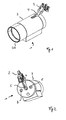
- the in the Fig. 1 and 2 illustrated and generally provided with the reference numeral 1 spotlight corresponds in terms of their basic structure a classic spotlight. It has an assembly and contacting element 2, which is connected via an arm 4 with a substantially cylindrical radiator housing 3.
- the mounting and contacting element 2 is intended to be attached to a substantially U-shaped - not shown - support rail. It has laterally protruding or swing-out locking elements, which cause a mechanical support on the mounting rail.
- laterally swing-out contacting elements are provided, via which then a Connection can be made with power supply lines.
- Such elements for mounting and contacting for lights in general, but in particular for radiators are already known from the prior art.
- the light source of the radiator 1 is arranged, whose light is emitted via a located on the front of the housing 3 front ring 30.
- a hinge arrangement is formed in the rear region of the housing 3, which allows a pivoting of the housing 3 relative to the connecting arm 4.
- the arm 4 extends into a slot-shaped recess 5 in the rear region of the housing 3.
- two screws are arranged on the rear side of the housing 3, wherein a longitudinal position of the light source within the housing 3 can be changed via a first screw 6 in order to set the focal point of the radiator.
- the braking force of the device described in more detail below for detecting the radiator housing 3 can be adjusted in a desired pivot position.
- This braking mechanism is in particular the 3 and 4 to take closer, the following are to be discussed in more detail.
- the 3 and 4 show views of the rear portion of the radiator housing 3 with removed cover.
- the embodiment of the joint 10 can be recognized, which allows pivoting of the housing 3 about a pivot axis I.
- the hinge assembly 10 is in this case formed in that the arm 4 has a fork-shaped element 11 with two lateral arms at the front end, which serve in each case for holding disk-shaped guide parts 12.
- a through hole is provided in each case, which is penetrated by a sleeve 13, wherein the sleeves 13 at the same time pass through corresponding openings of guide members 14, which are fixedly mounted on the housing 3. Accordingly, this arrangement enables the disc-shaped guide parts 12 to be rotated relative to the parts 14 about the axis I and thus the spotlight housing 3 can be pivoted.
- the horizontal radiation angle of the spotlight 1 can be adjusted accordingly in the desired manner.
- a special brake mechanism is provided, which also the 3 and 4 can be removed.
- the brake mechanism has here as a central element on a brake band 20, which is curved about the disc-shaped guide member 12 of one of the two arms of the fork part 11.
- This brake band 20 thus abuts against the outer circumference of the disc-shaped part 12 and exerts a certain braking force on the part 12 depending on the tension of the band 20, which ultimately inhibits further pivoting of the housing 3 about the axis I.
- the adjustment of the braking force can accordingly be adjusted by varying the tension of the brake band 20.
- the band 20 is coupled at its end with a nut 21 which cooperates with the adjusting screw 7.
- the longitudinal position of the nut 21 and thus the tension of the belt 20 can be adjusted accordingly.
- the head of the screw 7 is easily accessible from the back of the housing 3, accordingly, the braking force can be adjusted in a very simple and comfortable way.
- a special feature of the braking mechanism according to the invention is in particular that the braking force can be adjusted almost continuously. Accordingly, the braking effect can be tuned very precisely to the current arrangement and design of the radiator 1.
- a braking force can be set without further ado, which prevents an independent adjustment of the housing 3 relative to the assembly and contacting element 2, but at the same time still allows a manual pivoting. The optimal alignment of the spotlight 1 with respect to a desired lighting situation is accordingly significantly simplified.
- FIG. 5 to 10 Another feature of the radiator according to the invention is based on the Fig. 5 to 10 be explained.
- This development relates in particular to the possibility of making a change of the light source of the radiator 1 comfortable.
- the front end portion of the radiator 1 can be removed in a simple manner to gain access to the light source to be replaced.
- the front ring located at the front ring 30 is removed, via which the light emission of the radiator 1 takes place.
- the other elements located in the emission direction in front of the light source should also be removed, so that finally the elements in the Fig. 5 to 7 shown unit is released from the radiator housing 3.
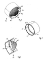
- This unit initially comprises the front ring 30, which at the same time, however, also holds a pot-shaped reflector 40, on whose bottom side an opening 41 is formed, through which the light source projects in the assembled state of the front ring 30.
- the holder of the reflector 40 on the front ring 30 is effected by means of a plurality of spring elements 42 which are arranged on the inside of the front ring 30. When inserting the reflector 40 from the back into the front ring 30, this locks with the springs 42 and is accordingly held securely in the front ring 30.
- the radiator 1 can be provided in the radiator 1 that the light output is influenced by certain optical means. These may be lenses or filters. Also, optical elements which have directional properties, such as so-called. Ovalzeichner or the like. Can be used.
- a disc 45 is shown, which, for example, a filter or the like. May represent.
- Accessory ring 50 in particular the representation in Fig. 8 can be removed.
- This accessory ring 50 is disposed within the front ring 30 and has a leaf spring 51, by means of which the disc 45 can be held in the desired position.
- the holder of the accessory ring 50 within the front ring 30 by means of other spring elements 52, which in particular the representation in Fig. 9 can be removed.
- the above-mentioned springs 52 for holding the accessory ring 50 in the front ring 30 are formed so as to allow a relative rotation of the accessory ring 50 with respect to the front ring 30. This is also quite desirable, since - when using direction-dependent accessories for influencing the optical light output - an adjustment should be possible. At the same time, however, there is the risk that, when the front ring 30 is removed, in order, for example, to carry out a lamp replacement, an adjustment of the accessory ring 50 takes place at the same time. After the lamp replacement and replacement of the front ring 30 can be required accordingly subsequent adjustment of the accessory ring.
- the arrangement accordingly additionally has a special locking device whose essential element is an additional spring 60 whose arrangement Fig. 9 is removable and the individually in Fig. 10 is shown.
- This spring is in turn arranged on the inner circumference of the front ring 30 and has a front projection 61, which engages in a trained at the rear end of the accessory ring 50 circumferential teeth 53.
- the spring 60 is in particular designed such that the engagement of the projection 61 takes place when the front ring 30 is removed together with the accessory ring 50 of the radiator housing 3.
- the spring 61 prevents a relative rotation of the accessory ring 50 relative to the front ring 30, so that it is ensured that no unintentional adjustment of any optical elements takes place.
- the spring 60 is designed such that it abuts with its rear side against a front edge of the housing 3 in the mounted state of the front ring 30. This has the consequence that the spring 60 is deflected in such a way that the projection 61 is out of engagement with the toothing 53 of the accessory ring 50.
- the front ring 30 In the assembled state of the front ring 30 so again there is the possibility of a Adjustment of the accessory ring 50 and thus make an adjustment of the optical properties.
- this additional locking spring 60 is thus ensured that in a temporary removal of the front ring 30 after its arrangement on the housing 3, the accessory ring 50 and thus the optical element 45 is automatically in the correct position or position again.
- This is also ensured by the fact that the mounting of the front ring 30 on the housing 3 in principle takes place in the same way.
- 3 guide recesses 8 are formed for this purpose on the circumference of the front end of the housing, which cooperate with corresponding projections on the inside of the front ring 30 in the sense of a bayonet connection.
- the recesses 8 and the projections on the front ring 30 are designed such that only the mounting of the front ring 30 is made possible in a clearly defined position. This can be done, for example, by a different configuration of the thickness of the projections on the front ring.
Landscapes
- Engineering & Computer Science (AREA)
- General Engineering & Computer Science (AREA)
- Non-Portable Lighting Devices Or Systems Thereof (AREA)
- Securing Globes, Refractors, Reflectors Or The Like (AREA)
- Pivots And Pivotal Connections (AREA)
Claims (6)
- Projecteur (1) comprenant un élément de montage (2) ainsi qu'un boîtier de projecteur (3), qui est relié à l'élément de montage (2) de manière à pouvoir pivoter par l'intermédiaire d'un ensemble d'articulations (10),
sachant que l'ensemble d'articulations (10) présente un mécanisme de freinage servant à immobiliser le boîtier (3) du projecteur dans une position de pivotement,
caractérisé en ce
que le mécanisme de freinage présente une bande de freinage (20), qui agit sur une partie mobile (12) de l'ensemble d'articulations (10), sachant que la force de la bande de freinage (20) peut être réglée, et
en ce qu'un anneau frontal (30) ainsi qu'un anneau accessoire (50) se trouvant à l'intérieur de l'anneau frontal (30) servant au maintien d'éléments optiques (45) sont disposés au niveau de l'extrémité avant du boîtier de projecteur (3),
sachant qu'un élément de blocage (60) est disposé au niveau de l'anneau frontal (30), lequel élément de blocage bloque, lorsque l'anneau frontal (30) est retiré, l'anneau accessoire (50) dans l'anneau frontal (30), et
sachant que le blocage de l'anneau accessoire (50) est déclenché lorsque l'anneau frontal (30) est monté au niveau du boîtier de projecteur (3). - Projecteur selon la revendication 1,
caractérisé en ce
que la bande de freinage (20) est incurvée de manière à présenter une forme de boucle autour de la partie mobile (12) de l'ensemble d'articulations (10). - Projecteur selon la revendication 2,
caractérisé en ce
que la bande de freinage (20) est couplée, au niveau de l'extrémité faisant face à la partie mobile (21), à l'aide de moyens servant à régler la tension de la bande de freinage (20). - Projecteur selon la revendication 3,
caractérisé en ce
que la bande de freinage (20) est couplée à une vis de réglage (7). - Projecteur selon l'une quelconque des revendications précédentes,
caractérisé en ce
que l'élément de blocage (60) est formé par un ressort, qui vient en prise avec une denture réalisée au niveau de l'anneau accessoire (50) lorsque l'anneau frontal (30) est retiré. - Projecteur selon l'une quelconque des revendications précédentes,
caractérisé en ce
qu'un réflecteur (40) s'engrène avec l'anneau frontal (30) et peut être retiré, conjointement avec ledit anneau frontal, du boîtier (2).
Applications Claiming Priority (2)
| Application Number | Priority Date | Filing Date | Title |
|---|---|---|---|
| DE202008004448U DE202008004448U1 (de) | 2008-04-01 | 2008-04-01 | Strahlerleuchte |
| PCT/EP2009/002385 WO2009121587A2 (fr) | 2008-04-01 | 2009-04-01 | Projecteur |
Publications (2)
| Publication Number | Publication Date |
|---|---|
| EP2260235A2 EP2260235A2 (fr) | 2010-12-15 |
| EP2260235B1 true EP2260235B1 (fr) | 2014-11-26 |
Family
ID=40718839
Family Applications (1)
| Application Number | Title | Priority Date | Filing Date |
|---|---|---|---|
| EP09727386.6A Active EP2260235B1 (fr) | 2008-04-01 | 2009-04-01 | Projecteur |
Country Status (4)
| Country | Link |
|---|---|
| EP (1) | EP2260235B1 (fr) |
| CN (1) | CN101981371B (fr) |
| DE (1) | DE202008004448U1 (fr) |
| WO (1) | WO2009121587A2 (fr) |
Families Citing this family (5)
| Publication number | Priority date | Publication date | Assignee | Title |
|---|---|---|---|---|
| DE102012205237B4 (de) * | 2012-03-30 | 2019-11-28 | Andreas Hierzer | Leuchte zur Verwendung in einer Beleuchtungsanordnung |
| DE202015103514U1 (de) * | 2015-07-03 | 2016-10-10 | Zumtobel Lighting Gmbh | Strahler mit verschiebbarem optischem Element |
| DE102018122093A1 (de) * | 2018-09-11 | 2020-03-12 | Zumtobel Lighting Gmbh | Leuchte |
| DE202021101564U1 (de) * | 2021-03-25 | 2022-06-28 | Zumtobel Lighting Gmbh | Leuchte mit sicherer Befestigung von Aufsätzen |
| IT202300022212A1 (it) * | 2023-10-24 | 2025-04-24 | A A G Stucchi S R L | Apparecchio di illuminazione con corpo di illuminazione orientabile |
Family Cites Families (16)
| Publication number | Priority date | Publication date | Assignee | Title |
|---|---|---|---|---|
| DE403846C (de) * | 1924-10-08 | Schneider & Co Dr Ing | Kipplampe | |
| DE397011C (de) * | 1923-07-06 | 1924-06-13 | C & W Bohnert | Drehgelenk, namentlich fuer Kipplampen |
| US2094656A (en) * | 1936-03-25 | 1937-10-05 | Edward E Holt | Electric light fixture |
| US5432683A (en) * | 1993-08-24 | 1995-07-11 | Brown; Douglas | Photographic lighting system |
| DE4344431A1 (de) * | 1993-12-24 | 1995-06-29 | Zumtobel Licht | Halterung von Zubehörteilen für Leuchten |
| DE9419593U1 (de) * | 1994-12-07 | 1995-02-02 | Reitzig, Irene, 47661 Issum | Unterwasserlampe |
| US5649761A (en) * | 1995-08-11 | 1997-07-22 | Larry C. Y. Lee | Motion detector with side-pivoting light fixture |
| DE19926561A1 (de) * | 1999-06-11 | 2000-12-14 | Diehl Stiftung & Co | Strahler, insbesondere Leseleuchte in Kabinen von Fahrzeugen |
| US6793379B2 (en) * | 2001-11-01 | 2004-09-21 | Lucifer Lighting Company | Configurable track or monopoint light |
| CN2522728Y (zh) * | 2002-01-16 | 2002-11-27 | 黄建英 | 嵌灯 |
| DE10206967A1 (de) * | 2002-01-23 | 2003-07-31 | Zumtobel Staff Gmbh & Co Kg | Lichtstrahler mit Reflektor |
| CN2639704Y (zh) * | 2003-09-01 | 2004-09-08 | 东莞市星锐灯饰有限公司 | 灯具结构 |
| DE202004017825U1 (de) * | 2004-11-17 | 2005-01-05 | Striewski, Hans | Leuchte |
| CN2758580Y (zh) * | 2004-12-31 | 2006-02-15 | 沈伟宏 | 调焦式灯具 |
| US7488092B2 (en) * | 2005-08-05 | 2009-02-10 | Genlyte Thomas Group Llc | Track fixture with hinged accessory ring |
| CN2883917Y (zh) * | 2005-12-14 | 2007-03-28 | 方曙光 | 新型感应灯 |
-
2008
- 2008-04-01 DE DE202008004448U patent/DE202008004448U1/de not_active Expired - Lifetime
-
2009
- 2009-04-01 CN CN200980111765XA patent/CN101981371B/zh not_active Expired - Fee Related
- 2009-04-01 WO PCT/EP2009/002385 patent/WO2009121587A2/fr not_active Ceased
- 2009-04-01 EP EP09727386.6A patent/EP2260235B1/fr active Active
Also Published As
| Publication number | Publication date |
|---|---|
| WO2009121587A8 (fr) | 2010-01-07 |
| EP2260235A2 (fr) | 2010-12-15 |
| DE202008004448U1 (de) | 2009-08-13 |
| WO2009121587A3 (fr) | 2009-11-26 |
| CN101981371B (zh) | 2013-09-11 |
| WO2009121587A2 (fr) | 2009-10-08 |
| CN101981371A (zh) | 2011-02-23 |
Similar Documents
| Publication | Publication Date | Title |
|---|---|---|
| DE69721459T2 (de) | Fahrzeugscheinwerfer mit Einstelleinrichtung des Reflektors | |
| EP2093478B1 (fr) | Lampe intégrée | |
| DE3602993C2 (fr) | ||
| AT513915B1 (de) | Lichtmodul sowie Beleuchtungsvorrichtung mit Lichtmodul für einen Fahrzeugscheinwerfer | |
| DE102005044237B4 (de) | Modularer Scheinwerfer | |
| DE202013104140U1 (de) | Einbauleuchte | |
| WO2009121587A2 (fr) | Projecteur | |
| WO2010079205A1 (fr) | Luminaire pourvu d'un châssis intérieur au moins partiellement amovible | |
| DE69312213T2 (de) | Scheinwerfer für Fahrzeuge | |
| DE202013101824U1 (de) | Leuchte mit einstellbarer Lichtabstrahlcharakteristik | |
| EP1483529A1 (fr) | Bras articule, en particulier pour un appareil destine a la prise de vues optique d'objets | |
| DE2618310C3 (de) | Strahlerleuchte | |
| DE102004042802A1 (de) | Strahler | |
| DE102008011170B4 (de) | Scheinwerfer, insbesondere Kraftfahrzeugscheinwerfer | |
| DE202012104544U1 (de) | Deckeneinbauleuchte | |
| DE69605063T2 (de) | Scheinwerfer | |
| EP0974786A2 (fr) | Phare du type projecteur pour véhicules | |
| DE10321282B4 (de) | Wandleuchte | |
| EP4314642A1 (fr) | Unité d'éclairage pour fixer de manière fiable des accessoires | |
| EP3862629B1 (fr) | Luminaire | |
| EP2107298A1 (fr) | Lampe suspendue allongée | |
| AT506090A4 (de) | Verstellbare lampenhalterung | |
| DE2737331C3 (de) | Halterung für ein eine Lampe umschließendes Leuchtengehäuse | |
| EP0012830A1 (fr) | Appareil d'éclairage à tube fluorescent | |
| DE202010016151U1 (de) | Beleuchtungseinrichtung mit platzsparend zu bedienenden Mitteln zur Lampenbefestigung |
Legal Events
| Date | Code | Title | Description |
|---|---|---|---|
| PUAI | Public reference made under article 153(3) epc to a published international application that has entered the european phase |
Free format text: ORIGINAL CODE: 0009012 |
|
| 17P | Request for examination filed |
Effective date: 20100929 |
|
| AK | Designated contracting states |
Kind code of ref document: A2 Designated state(s): AT BE BG CH CY CZ DE DK EE ES FI FR GB GR HR HU IE IS IT LI LT LU LV MC MK MT NL NO PL PT RO SE SI SK TR |
|
| AX | Request for extension of the european patent |
Extension state: AL BA RS |
|
| DAX | Request for extension of the european patent (deleted) | ||
| GRAP | Despatch of communication of intention to grant a patent |
Free format text: ORIGINAL CODE: EPIDOSNIGR1 |
|
| INTG | Intention to grant announced |
Effective date: 20140715 |
|
| GRAS | Grant fee paid |
Free format text: ORIGINAL CODE: EPIDOSNIGR3 |
|
| GRAA | (expected) grant |
Free format text: ORIGINAL CODE: 0009210 |
|
| AK | Designated contracting states |
Kind code of ref document: B1 Designated state(s): AT BE BG CH CY CZ DE DK EE ES FI FR GB GR HR HU IE IS IT LI LT LU LV MC MK MT NL NO PL PT RO SE SI SK TR |
|
| REG | Reference to a national code |
Ref country code: GB Ref legal event code: FG4D Free format text: NOT ENGLISH |
|
| REG | Reference to a national code |
Ref country code: CH Ref legal event code: NV Representative=s name: FIAMMENGHI-FIAMMENGHI, CH Ref country code: CH Ref legal event code: EP |
|
| REG | Reference to a national code |
Ref country code: AT Ref legal event code: REF Ref document number: 698417 Country of ref document: AT Kind code of ref document: T Effective date: 20141215 |
|
| REG | Reference to a national code |
Ref country code: IE Ref legal event code: FG4D Free format text: LANGUAGE OF EP DOCUMENT: GERMAN |
|
| REG | Reference to a national code |
Ref country code: DE Ref legal event code: R096 Ref document number: 502009010270 Country of ref document: DE Effective date: 20141231 |
|
| REG | Reference to a national code |
Ref country code: NL Ref legal event code: VDEP Effective date: 20141126 |
|
| REG | Reference to a national code |
Ref country code: LT Ref legal event code: MG4D |
|
| PG25 | Lapsed in a contracting state [announced via postgrant information from national office to epo] |
Ref country code: ES Free format text: LAPSE BECAUSE OF FAILURE TO SUBMIT A TRANSLATION OF THE DESCRIPTION OR TO PAY THE FEE WITHIN THE PRESCRIBED TIME-LIMIT Effective date: 20141126 Ref country code: LT Free format text: LAPSE BECAUSE OF FAILURE TO SUBMIT A TRANSLATION OF THE DESCRIPTION OR TO PAY THE FEE WITHIN THE PRESCRIBED TIME-LIMIT Effective date: 20141126 Ref country code: NL Free format text: LAPSE BECAUSE OF FAILURE TO SUBMIT A TRANSLATION OF THE DESCRIPTION OR TO PAY THE FEE WITHIN THE PRESCRIBED TIME-LIMIT Effective date: 20141126 Ref country code: PT Free format text: LAPSE BECAUSE OF FAILURE TO SUBMIT A TRANSLATION OF THE DESCRIPTION OR TO PAY THE FEE WITHIN THE PRESCRIBED TIME-LIMIT Effective date: 20150326 Ref country code: FI Free format text: LAPSE BECAUSE OF FAILURE TO SUBMIT A TRANSLATION OF THE DESCRIPTION OR TO PAY THE FEE WITHIN THE PRESCRIBED TIME-LIMIT Effective date: 20141126 Ref country code: NO Free format text: LAPSE BECAUSE OF FAILURE TO SUBMIT A TRANSLATION OF THE DESCRIPTION OR TO PAY THE FEE WITHIN THE PRESCRIBED TIME-LIMIT Effective date: 20150226 Ref country code: IS Free format text: LAPSE BECAUSE OF FAILURE TO SUBMIT A TRANSLATION OF THE DESCRIPTION OR TO PAY THE FEE WITHIN THE PRESCRIBED TIME-LIMIT Effective date: 20150326 |
|
| PG25 | Lapsed in a contracting state [announced via postgrant information from national office to epo] |
Ref country code: HR Free format text: LAPSE BECAUSE OF FAILURE TO SUBMIT A TRANSLATION OF THE DESCRIPTION OR TO PAY THE FEE WITHIN THE PRESCRIBED TIME-LIMIT Effective date: 20141126 Ref country code: SE Free format text: LAPSE BECAUSE OF FAILURE TO SUBMIT A TRANSLATION OF THE DESCRIPTION OR TO PAY THE FEE WITHIN THE PRESCRIBED TIME-LIMIT Effective date: 20141126 Ref country code: GR Free format text: LAPSE BECAUSE OF FAILURE TO SUBMIT A TRANSLATION OF THE DESCRIPTION OR TO PAY THE FEE WITHIN THE PRESCRIBED TIME-LIMIT Effective date: 20150227 Ref country code: LV Free format text: LAPSE BECAUSE OF FAILURE TO SUBMIT A TRANSLATION OF THE DESCRIPTION OR TO PAY THE FEE WITHIN THE PRESCRIBED TIME-LIMIT Effective date: 20141126 Ref country code: CY Free format text: LAPSE BECAUSE OF FAILURE TO SUBMIT A TRANSLATION OF THE DESCRIPTION OR TO PAY THE FEE WITHIN THE PRESCRIBED TIME-LIMIT Effective date: 20141126 |
|
| PG25 | Lapsed in a contracting state [announced via postgrant information from national office to epo] |
Ref country code: RO Free format text: LAPSE BECAUSE OF FAILURE TO SUBMIT A TRANSLATION OF THE DESCRIPTION OR TO PAY THE FEE WITHIN THE PRESCRIBED TIME-LIMIT Effective date: 20141126 Ref country code: DK Free format text: LAPSE BECAUSE OF FAILURE TO SUBMIT A TRANSLATION OF THE DESCRIPTION OR TO PAY THE FEE WITHIN THE PRESCRIBED TIME-LIMIT Effective date: 20141126 Ref country code: EE Free format text: LAPSE BECAUSE OF FAILURE TO SUBMIT A TRANSLATION OF THE DESCRIPTION OR TO PAY THE FEE WITHIN THE PRESCRIBED TIME-LIMIT Effective date: 20141126 Ref country code: SK Free format text: LAPSE BECAUSE OF FAILURE TO SUBMIT A TRANSLATION OF THE DESCRIPTION OR TO PAY THE FEE WITHIN THE PRESCRIBED TIME-LIMIT Effective date: 20141126 Ref country code: CZ Free format text: LAPSE BECAUSE OF FAILURE TO SUBMIT A TRANSLATION OF THE DESCRIPTION OR TO PAY THE FEE WITHIN THE PRESCRIBED TIME-LIMIT Effective date: 20141126 |
|
| REG | Reference to a national code |
Ref country code: DE Ref legal event code: R097 Ref document number: 502009010270 Country of ref document: DE |
|
| PG25 | Lapsed in a contracting state [announced via postgrant information from national office to epo] |
Ref country code: PL Free format text: LAPSE BECAUSE OF FAILURE TO SUBMIT A TRANSLATION OF THE DESCRIPTION OR TO PAY THE FEE WITHIN THE PRESCRIBED TIME-LIMIT Effective date: 20141126 |
|
| PLBE | No opposition filed within time limit |
Free format text: ORIGINAL CODE: 0009261 |
|
| STAA | Information on the status of an ep patent application or granted ep patent |
Free format text: STATUS: NO OPPOSITION FILED WITHIN TIME LIMIT |
|
| 26N | No opposition filed |
Effective date: 20150827 |
|
| PG25 | Lapsed in a contracting state [announced via postgrant information from national office to epo] |
Ref country code: LU Free format text: LAPSE BECAUSE OF FAILURE TO SUBMIT A TRANSLATION OF THE DESCRIPTION OR TO PAY THE FEE WITHIN THE PRESCRIBED TIME-LIMIT Effective date: 20150401 Ref country code: MC Free format text: LAPSE BECAUSE OF FAILURE TO SUBMIT A TRANSLATION OF THE DESCRIPTION OR TO PAY THE FEE WITHIN THE PRESCRIBED TIME-LIMIT Effective date: 20141126 |
|
| PG25 | Lapsed in a contracting state [announced via postgrant information from national office to epo] |
Ref country code: IT Free format text: LAPSE BECAUSE OF FAILURE TO SUBMIT A TRANSLATION OF THE DESCRIPTION OR TO PAY THE FEE WITHIN THE PRESCRIBED TIME-LIMIT Effective date: 20141126 |
|
| REG | Reference to a national code |
Ref country code: IE Ref legal event code: MM4A |
|
| PG25 | Lapsed in a contracting state [announced via postgrant information from national office to epo] |
Ref country code: SI Free format text: LAPSE BECAUSE OF FAILURE TO SUBMIT A TRANSLATION OF THE DESCRIPTION OR TO PAY THE FEE WITHIN THE PRESCRIBED TIME-LIMIT Effective date: 20141126 |
|
| REG | Reference to a national code |
Ref country code: FR Ref legal event code: PLFP Year of fee payment: 8 |
|
| PG25 | Lapsed in a contracting state [announced via postgrant information from national office to epo] |
Ref country code: IE Free format text: LAPSE BECAUSE OF NON-PAYMENT OF DUE FEES Effective date: 20150401 |
|
| PG25 | Lapsed in a contracting state [announced via postgrant information from national office to epo] |
Ref country code: MT Free format text: LAPSE BECAUSE OF FAILURE TO SUBMIT A TRANSLATION OF THE DESCRIPTION OR TO PAY THE FEE WITHIN THE PRESCRIBED TIME-LIMIT Effective date: 20141126 |
|
| REG | Reference to a national code |
Ref country code: FR Ref legal event code: PLFP Year of fee payment: 9 |
|
| PG25 | Lapsed in a contracting state [announced via postgrant information from national office to epo] |
Ref country code: HU Free format text: LAPSE BECAUSE OF FAILURE TO SUBMIT A TRANSLATION OF THE DESCRIPTION OR TO PAY THE FEE WITHIN THE PRESCRIBED TIME-LIMIT; INVALID AB INITIO Effective date: 20090401 Ref country code: BG Free format text: LAPSE BECAUSE OF FAILURE TO SUBMIT A TRANSLATION OF THE DESCRIPTION OR TO PAY THE FEE WITHIN THE PRESCRIBED TIME-LIMIT Effective date: 20141126 |
|
| PG25 | Lapsed in a contracting state [announced via postgrant information from national office to epo] |
Ref country code: BE Free format text: LAPSE BECAUSE OF NON-PAYMENT OF DUE FEES Effective date: 20150430 |
|
| PG25 | Lapsed in a contracting state [announced via postgrant information from national office to epo] |
Ref country code: TR Free format text: LAPSE BECAUSE OF FAILURE TO SUBMIT A TRANSLATION OF THE DESCRIPTION OR TO PAY THE FEE WITHIN THE PRESCRIBED TIME-LIMIT Effective date: 20141126 |
|
| REG | Reference to a national code |
Ref country code: FR Ref legal event code: PLFP Year of fee payment: 10 |
|
| PG25 | Lapsed in a contracting state [announced via postgrant information from national office to epo] |
Ref country code: MK Free format text: LAPSE BECAUSE OF FAILURE TO SUBMIT A TRANSLATION OF THE DESCRIPTION OR TO PAY THE FEE WITHIN THE PRESCRIBED TIME-LIMIT Effective date: 20141126 |
|
| PGFP | Annual fee paid to national office [announced via postgrant information from national office to epo] |
Ref country code: CH Payment date: 20180426 Year of fee payment: 10 |
|
| PGFP | Annual fee paid to national office [announced via postgrant information from national office to epo] |
Ref country code: AT Payment date: 20180426 Year of fee payment: 10 |
|
| REG | Reference to a national code |
Ref country code: CH Ref legal event code: PL |
|
| REG | Reference to a national code |
Ref country code: AT Ref legal event code: MM01 Ref document number: 698417 Country of ref document: AT Kind code of ref document: T Effective date: 20190401 |
|
| PG25 | Lapsed in a contracting state [announced via postgrant information from national office to epo] |
Ref country code: LI Free format text: LAPSE BECAUSE OF NON-PAYMENT OF DUE FEES Effective date: 20190430 Ref country code: CH Free format text: LAPSE BECAUSE OF NON-PAYMENT OF DUE FEES Effective date: 20190430 Ref country code: AT Free format text: LAPSE BECAUSE OF NON-PAYMENT OF DUE FEES Effective date: 20190401 |
|
| PGFP | Annual fee paid to national office [announced via postgrant information from national office to epo] |
Ref country code: FR Payment date: 20220427 Year of fee payment: 14 |
|
| REG | Reference to a national code |
Ref country code: DE Ref legal event code: R084 Ref document number: 502009010270 Country of ref document: DE |
|
| P01 | Opt-out of the competence of the unified patent court (upc) registered |
Effective date: 20230530 |
|
| PG25 | Lapsed in a contracting state [announced via postgrant information from national office to epo] |
Ref country code: FR Free format text: LAPSE BECAUSE OF NON-PAYMENT OF DUE FEES Effective date: 20230430 |
|
| PGFP | Annual fee paid to national office [announced via postgrant information from national office to epo] |
Ref country code: GB Payment date: 20240423 Year of fee payment: 16 |
|
| PGFP | Annual fee paid to national office [announced via postgrant information from national office to epo] |
Ref country code: DE Payment date: 20250428 Year of fee payment: 17 |
|
| GBPC | Gb: european patent ceased through non-payment of renewal fee |
Effective date: 20250401 |
|
| PG25 | Lapsed in a contracting state [announced via postgrant information from national office to epo] |
Ref country code: GB Free format text: LAPSE BECAUSE OF NON-PAYMENT OF DUE FEES Effective date: 20250401 |