EP2260687A1 - Tour de montage pour appareil de montage arrière - Google Patents
Tour de montage pour appareil de montage arrière Download PDFInfo
- Publication number
- EP2260687A1 EP2260687A1 EP10006001A EP10006001A EP2260687A1 EP 2260687 A1 EP2260687 A1 EP 2260687A1 EP 10006001 A EP10006001 A EP 10006001A EP 10006001 A EP10006001 A EP 10006001A EP 2260687 A1 EP2260687 A1 EP 2260687A1
- Authority
- EP
- European Patent Office
- Prior art keywords
- coupling
- attachment
- point
- tower
- tractor
- Prior art date
- Legal status (The legal status is an assumption and is not a legal conclusion. Google has not performed a legal analysis and makes no representation as to the accuracy of the status listed.)
- Granted
Links
Images


Classifications
-
- A—HUMAN NECESSITIES
- A01—AGRICULTURE; FORESTRY; ANIMAL HUSBANDRY; HUNTING; TRAPPING; FISHING
- A01B—SOIL WORKING IN AGRICULTURE OR FORESTRY; PARTS, DETAILS, OR ACCESSORIES OF AGRICULTURAL MACHINES OR IMPLEMENTS, IN GENERAL
- A01B59/00—Devices specially adapted for connection between animals or tractors and agricultural machines or implements
- A01B59/06—Devices specially adapted for connection between animals or tractors and agricultural machines or implements for machines mounted on tractors
- A01B59/066—Devices specially adapted for connection between animals or tractors and agricultural machines or implements for machines mounted on tractors of the type comprising at least two lower arms and one upper arm generally arranged in a triangle, e.g. three-point hitches
Definitions
- the invention relates to a cultivation tower for rear attachments such.
- B. field crop spraying Such extension towers have crosspoints that allow the attachment of the rear attachment to the three-point linkage of the tractor.
- This type of three-point cultivation today usually corresponds to the international standard ISO 730-1 from the interface between the tractor and the device. Based on this standard, there are various coupling systems that are designed to simplify attachment to the tractor. These are single-phase or multi-phase quick-coupling systems according to ISO 11001-1, ISO 11001-2, ISO 11001-3 and ISO 11001-4. These coupling systems all simplify the installation of a rear attachment to the three-point linkage of the tractor, but remains after installation only little space to z. B.
- the invention has for its object to provide a mounting tower for rear attachments that allows easy attachment of the rear attachments to the three-point linkage of a tractor and the case but also a dense and focus-favorable cultivation of the attachment to the tractor permits.
- the upper crosspoint is assigned in the manner described a component that is movable, and the dome position for connection with the upper link and for locking the upper crosspoint in working position with attached to the coupling point top link is variably movable.
- the top link of the tractor can be easily attached to the upper crosspoint of the rear implement, even if there is still a large distance between the tractor and rear attachment, z. B. 50 cm.
- the component is so changed in its position that the top link can be easily coupled to the upper crosspoint.
- the top link does not need to be changed in its length; he can remain in his optimal for the work length adjustment.
- the distance between the rear attachment and tractor in the growing phase of the upper link may be greater than 50 cm.
- the tractor After connecting the upper link to the upper coupling point and connecting the PTO shaft to the PTO of the tractor and after connecting all supply lines of the device, the tractor can then be moved close to the attachment and the connection between the lower link of the tractor and the lower coupling points of the Rear attachment can be made as usual. Since then not only the quick-coupling system of the tractor lower link is locked, but also the upper crosspoint in the working position, the device can be excavated without people still have to go between the tractor and the rear mounted implement,
- the invention further provides that the component is designed as a rocker, which for the connection with the top link in a front dome position and with the coupling point connected upper link in a rear working position is pivotable, wherein the rocker and thus also the upper coupling point in the working position can be locked and formed in the coupling position variably movable.
- the upper coupling point is associated with a component which is designed as a rocker and therefore, e.g. not slidable or telescopic but is pivotable.
- a component which is designed as a rocker and therefore, e.g. not slidable or telescopic but is pivotable.
- liquids are often used that cause corrosion.
- the reliability of pivotable components is greater than that of sliding or telescoping components in the long term.
- the three-point linkage of the tractor has a quick-coupling system with fishing hooks, e.g. the quick coupling system according to ISO-11001-3.
- the catch hooks, in particular on the lower links facilitate the connection of the lower link with the lower coupling points of the cultivation tower considerably.
- the invention further provides that the component or the rocker is formed automatically lockable via a locking system in the working position.
- This embodiment has the advantage that after mounting the device, the upper crosspoint is not manually, e.g. must be locked via a remote control but automatically locked.
- the locking system has guide elements, which prevents premature locking of the upper coupling point during the dome phase, allowing a limited maneuvering of the tractor during the dome phase and locking is formed only when lifting the rear attachment.
- This peculiarity of the invention ensures that after the cultivation of the upper link to the upper crosspoint, after connecting the propeller shaft to the PTO of the tractor and after connecting the supply lines to the corresponding connections and couplings of the tractor with the tractor so on the device can be moved up until the lower link can be connected via their quick coupling system with the lower coupling points.
- the rocker and connected to the rocker upper crosspoint remain variable in this phase of dome and are not locked.
- a required for connecting the lower link of the tractor with the lower coupling points of the rear attachment maneuvering is made possible and not complicated by premature locking of the upper crosspoint. Only after the lower links of the tractor are connected to the lower coupling points and the attachment is excavated, the upper crosspoint is locked in the working position.
- the mechanism is preferably designed so that the locking system and the guide elements consist of a dome hook with hooks, the dome hooks limited pivotally connected to its rear end via a transverse axis with the attachment tower and the counter hooks limited by a transverse joint pivotally connected to the front end of the dome hook is.
- the dome hook and the counter hooks are arranged to each other so that they do not allow a locking and locking the upper crosspoint when the tractor moves for the dome operation towards rear attachment. However, if the rear attachment is lifted, it is held by the dome hook and fixed by the counter hook and thus securely locked.
- a remote control is provided, via which the locking system is disengaged and so the rocker and the upper coupling point are formed from the working position to the dome position brought.
- the parked rear mounted implement can only be brought back from the working position into the variably movable dome position via a remote control.
- the lower links can be removed and driven so far away with the tractor until again a sufficient distance between Rear implement and tractor has emerged. If the distance is again large enough, the operator can again disassemble the PTO shaft, disconnect the supply lines from the tractor and remove the top link.
- the upper crosspoint between the working position and the dome position must be at least 15 cm to 20 cm horizontally movable.
- Optimal is a horizontal mobility of the upper dome point between 30 cm and 60 cm.
- the remote control is designed as a pull rope, which is kinematically connected via a linkage with the dome hooks.
- the quick coupling systems of the lower links are disengaged via pull cables. It therefore makes sense to disengage the upper crosspoint via the same method.
- systems which can be actuated hydraulically or electrically but which offer no advantages in terms of functional safety. This is also a reason why a mechanical system has been preferably selected for the inventive coupling system, e.g. no hydraulic system.
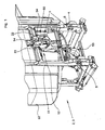
- FIG. 1 shows the rear attachment 2, in this case a mounted field sprayer 3, the front attachment tower 1 having the upper crosspoint 4 and the lower crosspoints 5 and 6.
- the lower crosspoints 5 and 6 are provided for lower links of tractors, which are equipped with a Schnellkuppelsystem and can be automatically and remotely coupled and disconnected.
- the upper crosspoint 4 is indirectly associated with the upper part 50 of the extension tower 1, which in turn is attached to the frame 51.
- the frame 51 carries the container 52 of the crop field sprayer 3. Under the container 52, the pump 53 is arranged, which is connected via a drive shaft, not shown, drivingly connected to the PTO of the tractor.
- the upper crosspoint 4 is assigned to the formed as a rocker member 10 9 and is here in the working position 12.
- FIG. 2 shows the upper part 50 of the attachment tower 1 in the dome position 11.
- the rocker 10 which is pivotally mounted about the axis 13 between the outer plates 54, is pivoted for coupling the upper link of the tractor forward.
- the rocker 10 and thus also the upper coupling point 4 are then no longer fixed by the dome hooks 22 and the counter hook 23.
- the rocker 10 can be variably swung more or less far to the front. Regardless of the length of the top link of the tractor so the top link can be easily connected to the upper crosspoint.
- the horizontal distance A in the working direction between the working position 12 and the coupling position 11 of the upper coupling point 4 results in the increased distance that is available to the operator when, after coupling the upper link for connecting the propeller shaft of the rear attachment 2 with the PTO of Tractor and for connecting the supply lines between the tractor and the rear attachment 2 goes.
- the variable mobility of the upper coupling point 4 is slightly larger than the distance A, since there must be available for the cultivation of the lower link to the lower crosspoints 5 and 6 opportunities for maneuvering.
- the dome hook 22 is in its lower position and is located at the lower end of the slots 55 of the outer plates 54 at.
- the counter hook 23 is also in its lower position and is located at the lower end of the slots 38 of the rods 36 at.
- the upper part 50 of the attachment tower 1 is bolted to the frame 51.
- FIG. 3 shows the upper part 50 of the mounting tower 1 in the dome position 11, 11 ', just before the locking of the upper coupling point 4 in the working position 12 with already connected to the upper crosspoint 4 upper link.
- an outer panel 54 has been hidden, as previously mentioned, and also the upper link of the tractor, which is already connected to the upper coupling point 4.
- the upper crosspoint 4 is located in the variably movable coupling position 11, in the dome position 11 ', in which the lower crosspoints 5.6 can be coupled.
- the upper crosspoint 4 must continue normally required to be pushed back into the tilling tower 1. He may then not be locked, because then a coupling of the lower crosspoints 5.6 is not possible.
- the upper crosspoint 4 slightly further forward and is fixed only in this working position 12 through the recesses 40 of the coupling hook 22 and the recesses 41 of the mating hook 23.
- the dome hook 22 is connected at its rear end 30 via the transverse axis 24 with the upper part 50 of the attachment tower 1.
- the counter hook 23 is connected via the transverse joint 25. If the upper dome point 4 is introduced during the dome phase in the upper part 50 of the attachment tower 1, it abuts against the leading edge 37 and pushes the dome hooks 22 together with counter hooks 23 upwards.
- the upper crosspoint 4 is pushed so far back until the lower crosspoints 5 and 6 can be coupled. During the shunting process required for this, the upper crosspoint 4 is not locked, since the support surface 65 of the counter hook 23 is supported on the upper crosspoint 4 and the counter hook 23 is kept high.
- the arrangement of the dome hook 22 and the counter hook 23 in conjunction with the support surface 65 of the counter hook 23 is designed so that premature locking of the upper coupling point 4 is prevented.
- An end limit 60 prevents the upper crosspoint 4 from being inserted too far into the upper part 50 of the attachment tower 1. this is the FIG. 2 refer to. If, after the coupling operation of the lower link, the upper coupling point 4 is moved forward again, it runs into the recess 40 of the coupling hook 22. At the same time, the counter-hook 23 drops down and, with its recess 41, also includes the upper cross-point 4. The upper cross-point 4 is then in the secured and locked working position 12, which is the FIG. 4 can be seen.
- FIG. 4 shows how the upper coupling point 4 between the recesses 40 and 41 of the dome hooks 22 and hooks 23 is firmly fixed. This corresponds, as already mentioned, to the working position 12, in which a displacement of the upper coupling point 4 is no longer possible.
- the locking system 20 is actuated accordingly via a linkage 29.
- the linkage 29 consists inter alia of an angle lever 35, a rod 36 and a pull cable 34.
- the pull cable 34 serves as a remote control 33.
- the upper crosspoint 4 is thus disengaged again.
- the lower links of the tractor can now be separated from the lower crosspoints 5.6, this can be ranked accordingly with the tractor.
- the tractor can be moved away from the rear attachment 2 until there is sufficient space between the rear attachment 2 and the tractor to remove the PTO shaft from the PTO shaft of the tractor and disconnect the supply lines.
- the rocker 10 is then not yet under tension and the top link can be easily and easily removed from the upper crosspoint 4.
Landscapes
- Life Sciences & Earth Sciences (AREA)
- Zoology (AREA)
- Engineering & Computer Science (AREA)
- Mechanical Engineering (AREA)
- Soil Sciences (AREA)
- Environmental Sciences (AREA)
- Agricultural Machines (AREA)
Applications Claiming Priority (1)
| Application Number | Priority Date | Filing Date | Title |
|---|---|---|---|
| DE200910024437 DE102009024437B4 (de) | 2009-06-10 | 2009-06-10 | Anbauturm für Heckanbaugerät |
Publications (2)
| Publication Number | Publication Date |
|---|---|
| EP2260687A1 true EP2260687A1 (fr) | 2010-12-15 |
| EP2260687B1 EP2260687B1 (fr) | 2016-07-20 |
Family
ID=42937193
Family Applications (1)
| Application Number | Title | Priority Date | Filing Date |
|---|---|---|---|
| EP10006001.1A Active EP2260687B1 (fr) | 2009-06-10 | 2010-06-10 | Tour de montage pour appareil de montage arrière |
Country Status (4)
| Country | Link |
|---|---|
| EP (1) | EP2260687B1 (fr) |
| DE (1) | DE102009024437B4 (fr) |
| DK (1) | DK2260687T3 (fr) |
| PL (1) | PL2260687T3 (fr) |
Cited By (5)
| Publication number | Priority date | Publication date | Assignee | Title |
|---|---|---|---|---|
| EP2918156A3 (fr) * | 2014-03-07 | 2015-11-25 | Amazonen-Werke H. Dreyer GmbH & Co. KG | Machine, en particulier agricole |
| ES2557058A1 (es) * | 2015-09-29 | 2016-01-21 | Exel Industries | Dispositivo de conexión de un accesorio agrícola a un vehículo agrícola tractor |
| EP3357315A1 (fr) * | 2017-02-01 | 2018-08-08 | Amazonen-Werke H. Dreyer GmbH & Co. KG | Dispositif d'accouplement pour un appareil de travail agricole |
| EP3357314A1 (fr) * | 2017-02-01 | 2018-08-08 | Amazonen-Werke H. Dreyer GmbH & Co. KG | Dispositif d'accouplement pour un appareil de travail agricole |
| FR3109259A1 (fr) * | 2020-04-20 | 2021-10-22 | Exel Industries | Ensemble de pulverisation agricole porte par un engin agricole au moyen d’un systeme d’attelage |
Citations (2)
| Publication number | Priority date | Publication date | Assignee | Title |
|---|---|---|---|---|
| DE19515253A1 (de) * | 1994-04-28 | 1995-11-02 | Krone Bernhard Gmbh Maschf | Anbaurahmen |
| DE10011401A1 (de) * | 2000-03-09 | 2001-09-13 | Amazonen Werke Dreyer H | Landwirtschaftliche Verteilmaschine |
Family Cites Families (1)
| Publication number | Priority date | Publication date | Assignee | Title |
|---|---|---|---|---|
| DE922021C (de) * | 1951-07-14 | 1955-01-07 | Hannoversche Maschb Aktien Ges | Anbauvorrichtung fuer ein am Schlepper an einem oberen und einem unteren Punkt schwingbar aufgehaengtes Bodenbearbeitungswerkzeug |
-
2009
- 2009-06-10 DE DE200910024437 patent/DE102009024437B4/de active Active
-
2010
- 2010-06-10 PL PL10006001T patent/PL2260687T3/pl unknown
- 2010-06-10 EP EP10006001.1A patent/EP2260687B1/fr active Active
- 2010-06-10 DK DK10006001.1T patent/DK2260687T3/en active
Patent Citations (2)
| Publication number | Priority date | Publication date | Assignee | Title |
|---|---|---|---|---|
| DE19515253A1 (de) * | 1994-04-28 | 1995-11-02 | Krone Bernhard Gmbh Maschf | Anbaurahmen |
| DE10011401A1 (de) * | 2000-03-09 | 2001-09-13 | Amazonen Werke Dreyer H | Landwirtschaftliche Verteilmaschine |
Cited By (7)
| Publication number | Priority date | Publication date | Assignee | Title |
|---|---|---|---|---|
| EP2918156A3 (fr) * | 2014-03-07 | 2015-11-25 | Amazonen-Werke H. Dreyer GmbH & Co. KG | Machine, en particulier agricole |
| ES2557058A1 (es) * | 2015-09-29 | 2016-01-21 | Exel Industries | Dispositivo de conexión de un accesorio agrícola a un vehículo agrícola tractor |
| EP3150036A1 (fr) | 2015-09-29 | 2017-04-05 | Exel Industries | Dispositif pour relier un accessoire agricole à un véhicule tracteur agricole |
| EP3357315A1 (fr) * | 2017-02-01 | 2018-08-08 | Amazonen-Werke H. Dreyer GmbH & Co. KG | Dispositif d'accouplement pour un appareil de travail agricole |
| EP3357314A1 (fr) * | 2017-02-01 | 2018-08-08 | Amazonen-Werke H. Dreyer GmbH & Co. KG | Dispositif d'accouplement pour un appareil de travail agricole |
| FR3109259A1 (fr) * | 2020-04-20 | 2021-10-22 | Exel Industries | Ensemble de pulverisation agricole porte par un engin agricole au moyen d’un systeme d’attelage |
| EP3900533A1 (fr) * | 2020-04-20 | 2021-10-27 | Exel Industries | Pulverisateur agricole porte par un engin agricole au moyen d'un systeme d'attelage |
Also Published As
| Publication number | Publication date |
|---|---|
| DE102009024437B4 (de) | 2011-06-30 |
| DK2260687T3 (en) | 2016-10-17 |
| DE102009024437A1 (de) | 2010-12-16 |
| EP2260687B1 (fr) | 2016-07-20 |
| PL2260687T3 (pl) | 2017-01-31 |
Similar Documents
| Publication | Publication Date | Title |
|---|---|---|
| DE1482841C3 (de) | Selbstfahrender Mähdrescher mit einer Mähwerkbaugruppe | |
| DE2541697C3 (de) | An einer Zugmaschine lösbar befestigbares Ladegerät | |
| DE2926727C2 (de) | Vorrichtung zur Veränderung des Winkels der an einem Ackerschlepper mit Druckmittelanschlußkupplungen angelenkten Deichsel und dem Querrahmen eines landwirtschaftlichen Gerätes | |
| DE602005005589T2 (de) | Schnellkupplungsvorrichtung sowie Traktor | |
| EP2260687B1 (fr) | Tour de montage pour appareil de montage arrière | |
| DE1757480A1 (de) | Landwirtschaftliches Fahrzeug mit Vorrichtung zum Koppeln von Anbaugeraeten | |
| DE6912500U (de) | Bodenbearbeitungsgeraet | |
| EP2910113A1 (fr) | Bras d'irrigation pour un véhicule porteur mobile, notamment un support d'appareil à voie étroite | |
| DE202011106833U1 (de) | Schnellkupplungssystem für Anbaugeräte, insbesondere für landwirtschaftliche Anbaugeräte | |
| DE1222726B (de) | Kupplungsvorrichtung zwischen einem Schlepper und einem an diesen anzubauenden Arbeitsgeraet | |
| DE1018726B (de) | Einachsige Zugmaschine, insbesondere fuer die Landwirtschaft | |
| EP3702537B1 (fr) | Véhicule utilitaire spécial | |
| EP0951816B1 (fr) | Vehicule pour le soin du terrain avec un outil de travail | |
| EP0161466B1 (fr) | Appareil agricole porté | |
| DE3831186A1 (de) | Heuwerbungsmaschine | |
| WO2024159248A1 (fr) | Adaptateur pour le montage d'un accessoire sur un véhicule porteur | |
| EP3753385B1 (fr) | Structure porteuse pour le raccordement de deux accessoires agricoles à un tracteur ainsi qu'accessoire agricole | |
| DE4310742A1 (de) | Vorrichtung zum Ankuppeln landwirtschaftlicher, verfahrbarer Anbaumaschinen an Schlepper | |
| DE102011086085A1 (de) | Anbaugerät für einen Bagger | |
| DE8715674U1 (de) | Heuwerbungsmaschine | |
| EP1830006B1 (fr) | Machine de travaux de construction et procédé pour la preparation du transport de cette machine | |
| EP1964808A2 (fr) | Plaque d'appui | |
| DE102019007751A1 (de) | Anbauvorrichtung zum Anbauen von mindestens einer landwirtschaftlichen Arbeitsmaschine an eine Zugmaschine sowie Arbeitszug mit der Zugmaschine, der Anbauvorrichtung und der landwirtschaftlichen Arbeitsmaschine | |
| EP0120415B1 (fr) | Attelage rapide pour tracteur agricole | |
| DE4130829C2 (de) | Anhängevorrichtung für Zugmaschinen |
Legal Events
| Date | Code | Title | Description |
|---|---|---|---|
| PUAI | Public reference made under article 153(3) epc to a published international application that has entered the european phase |
Free format text: ORIGINAL CODE: 0009012 |
|
| AK | Designated contracting states |
Kind code of ref document: A1 Designated state(s): AL AT BE BG CH CY CZ DE DK EE ES FI FR GB GR HR HU IE IS IT LI LT LU LV MC MK MT NL NO PL PT RO SE SI SK SM TR |
|
| AX | Request for extension of the european patent |
Extension state: BA ME RS |
|
| 17P | Request for examination filed |
Effective date: 20110615 |
|
| RIN1 | Information on inventor provided before grant (corrected) |
Inventor name: GIESEN, GOTTFRIED Inventor name: BOEGING, MICHAEL Inventor name: BASTEN, ALEXANDER |
|
| GRAP | Despatch of communication of intention to grant a patent |
Free format text: ORIGINAL CODE: EPIDOSNIGR1 |
|
| INTG | Intention to grant announced |
Effective date: 20160211 |
|
| GRAS | Grant fee paid |
Free format text: ORIGINAL CODE: EPIDOSNIGR3 |
|
| GRAA | (expected) grant |
Free format text: ORIGINAL CODE: 0009210 |
|
| AK | Designated contracting states |
Kind code of ref document: B1 Designated state(s): AL AT BE BG CH CY CZ DE DK EE ES FI FR GB GR HR HU IE IS IT LI LT LU LV MC MK MT NL NO PL PT RO SE SI SK SM TR |
|
| REG | Reference to a national code |
Ref country code: GB Ref legal event code: FG4D Free format text: NOT ENGLISH |
|
| REG | Reference to a national code |
Ref country code: CH Ref legal event code: EP |
|
| REG | Reference to a national code |
Ref country code: IE Ref legal event code: FG4D Free format text: LANGUAGE OF EP DOCUMENT: GERMAN |
|
| REG | Reference to a national code |
Ref country code: CH Ref legal event code: NV Representative=s name: WEINMANN ZIMMERLI, CH Ref country code: AT Ref legal event code: REF Ref document number: 813190 Country of ref document: AT Kind code of ref document: T Effective date: 20160815 |
|
| REG | Reference to a national code |
Ref country code: DE Ref legal event code: R096 Ref document number: 502010012034 Country of ref document: DE |
|
| REG | Reference to a national code |
Ref country code: DK Ref legal event code: T3 Effective date: 20161014 |
|
| REG | Reference to a national code |
Ref country code: NL Ref legal event code: FP |
|
| REG | Reference to a national code |
Ref country code: LT Ref legal event code: MG4D |
|
| PG25 | Lapsed in a contracting state [announced via postgrant information from national office to epo] |
Ref country code: HR Free format text: LAPSE BECAUSE OF FAILURE TO SUBMIT A TRANSLATION OF THE DESCRIPTION OR TO PAY THE FEE WITHIN THE PRESCRIBED TIME-LIMIT Effective date: 20160720 Ref country code: NO Free format text: LAPSE BECAUSE OF FAILURE TO SUBMIT A TRANSLATION OF THE DESCRIPTION OR TO PAY THE FEE WITHIN THE PRESCRIBED TIME-LIMIT Effective date: 20161020 Ref country code: FI Free format text: LAPSE BECAUSE OF FAILURE TO SUBMIT A TRANSLATION OF THE DESCRIPTION OR TO PAY THE FEE WITHIN THE PRESCRIBED TIME-LIMIT Effective date: 20160720 Ref country code: LT Free format text: LAPSE BECAUSE OF FAILURE TO SUBMIT A TRANSLATION OF THE DESCRIPTION OR TO PAY THE FEE WITHIN THE PRESCRIBED TIME-LIMIT Effective date: 20160720 Ref country code: IS Free format text: LAPSE BECAUSE OF FAILURE TO SUBMIT A TRANSLATION OF THE DESCRIPTION OR TO PAY THE FEE WITHIN THE PRESCRIBED TIME-LIMIT Effective date: 20161120 |
|
| PG25 | Lapsed in a contracting state [announced via postgrant information from national office to epo] |
Ref country code: ES Free format text: LAPSE BECAUSE OF FAILURE TO SUBMIT A TRANSLATION OF THE DESCRIPTION OR TO PAY THE FEE WITHIN THE PRESCRIBED TIME-LIMIT Effective date: 20160720 Ref country code: LV Free format text: LAPSE BECAUSE OF FAILURE TO SUBMIT A TRANSLATION OF THE DESCRIPTION OR TO PAY THE FEE WITHIN THE PRESCRIBED TIME-LIMIT Effective date: 20160720 Ref country code: GR Free format text: LAPSE BECAUSE OF FAILURE TO SUBMIT A TRANSLATION OF THE DESCRIPTION OR TO PAY THE FEE WITHIN THE PRESCRIBED TIME-LIMIT Effective date: 20161021 Ref country code: PT Free format text: LAPSE BECAUSE OF FAILURE TO SUBMIT A TRANSLATION OF THE DESCRIPTION OR TO PAY THE FEE WITHIN THE PRESCRIBED TIME-LIMIT Effective date: 20161121 Ref country code: SE Free format text: LAPSE BECAUSE OF FAILURE TO SUBMIT A TRANSLATION OF THE DESCRIPTION OR TO PAY THE FEE WITHIN THE PRESCRIBED TIME-LIMIT Effective date: 20160720 |
|
| REG | Reference to a national code |
Ref country code: DE Ref legal event code: R097 Ref document number: 502010012034 Country of ref document: DE |
|
| PG25 | Lapsed in a contracting state [announced via postgrant information from national office to epo] |
Ref country code: EE Free format text: LAPSE BECAUSE OF FAILURE TO SUBMIT A TRANSLATION OF THE DESCRIPTION OR TO PAY THE FEE WITHIN THE PRESCRIBED TIME-LIMIT Effective date: 20160720 Ref country code: RO Free format text: LAPSE BECAUSE OF FAILURE TO SUBMIT A TRANSLATION OF THE DESCRIPTION OR TO PAY THE FEE WITHIN THE PRESCRIBED TIME-LIMIT Effective date: 20160720 |
|
| PLBE | No opposition filed within time limit |
Free format text: ORIGINAL CODE: 0009261 |
|
| STAA | Information on the status of an ep patent application or granted ep patent |
Free format text: STATUS: NO OPPOSITION FILED WITHIN TIME LIMIT |
|
| PG25 | Lapsed in a contracting state [announced via postgrant information from national office to epo] |
Ref country code: SM Free format text: LAPSE BECAUSE OF FAILURE TO SUBMIT A TRANSLATION OF THE DESCRIPTION OR TO PAY THE FEE WITHIN THE PRESCRIBED TIME-LIMIT Effective date: 20160720 Ref country code: SK Free format text: LAPSE BECAUSE OF FAILURE TO SUBMIT A TRANSLATION OF THE DESCRIPTION OR TO PAY THE FEE WITHIN THE PRESCRIBED TIME-LIMIT Effective date: 20160720 Ref country code: BG Free format text: LAPSE BECAUSE OF FAILURE TO SUBMIT A TRANSLATION OF THE DESCRIPTION OR TO PAY THE FEE WITHIN THE PRESCRIBED TIME-LIMIT Effective date: 20161020 Ref country code: CZ Free format text: LAPSE BECAUSE OF FAILURE TO SUBMIT A TRANSLATION OF THE DESCRIPTION OR TO PAY THE FEE WITHIN THE PRESCRIBED TIME-LIMIT Effective date: 20160720 |
|
| 26N | No opposition filed |
Effective date: 20170421 |
|
| REG | Reference to a national code |
Ref country code: FR Ref legal event code: PLFP Year of fee payment: 8 |
|
| PG25 | Lapsed in a contracting state [announced via postgrant information from national office to epo] |
Ref country code: SI Free format text: LAPSE BECAUSE OF FAILURE TO SUBMIT A TRANSLATION OF THE DESCRIPTION OR TO PAY THE FEE WITHIN THE PRESCRIBED TIME-LIMIT Effective date: 20160720 |
|
| PG25 | Lapsed in a contracting state [announced via postgrant information from national office to epo] |
Ref country code: MC Free format text: LAPSE BECAUSE OF FAILURE TO SUBMIT A TRANSLATION OF THE DESCRIPTION OR TO PAY THE FEE WITHIN THE PRESCRIBED TIME-LIMIT Effective date: 20160720 |
|
| REG | Reference to a national code |
Ref country code: IE Ref legal event code: MM4A |
|
| PG25 | Lapsed in a contracting state [announced via postgrant information from national office to epo] |
Ref country code: IE Free format text: LAPSE BECAUSE OF NON-PAYMENT OF DUE FEES Effective date: 20170610 Ref country code: LU Free format text: LAPSE BECAUSE OF NON-PAYMENT OF DUE FEES Effective date: 20170610 |
|
| REG | Reference to a national code |
Ref country code: FR Ref legal event code: PLFP Year of fee payment: 9 |
|
| PG25 | Lapsed in a contracting state [announced via postgrant information from national office to epo] |
Ref country code: MT Free format text: LAPSE BECAUSE OF FAILURE TO SUBMIT A TRANSLATION OF THE DESCRIPTION OR TO PAY THE FEE WITHIN THE PRESCRIBED TIME-LIMIT Effective date: 20160720 |
|
| PG25 | Lapsed in a contracting state [announced via postgrant information from national office to epo] |
Ref country code: AL Free format text: LAPSE BECAUSE OF FAILURE TO SUBMIT A TRANSLATION OF THE DESCRIPTION OR TO PAY THE FEE WITHIN THE PRESCRIBED TIME-LIMIT Effective date: 20160720 |
|
| PG25 | Lapsed in a contracting state [announced via postgrant information from national office to epo] |
Ref country code: HU Free format text: LAPSE BECAUSE OF FAILURE TO SUBMIT A TRANSLATION OF THE DESCRIPTION OR TO PAY THE FEE WITHIN THE PRESCRIBED TIME-LIMIT; INVALID AB INITIO Effective date: 20100610 |
|
| PG25 | Lapsed in a contracting state [announced via postgrant information from national office to epo] |
Ref country code: CY Free format text: LAPSE BECAUSE OF NON-PAYMENT OF DUE FEES Effective date: 20160720 |
|
| PG25 | Lapsed in a contracting state [announced via postgrant information from national office to epo] |
Ref country code: MK Free format text: LAPSE BECAUSE OF FAILURE TO SUBMIT A TRANSLATION OF THE DESCRIPTION OR TO PAY THE FEE WITHIN THE PRESCRIBED TIME-LIMIT Effective date: 20160720 |
|
| PG25 | Lapsed in a contracting state [announced via postgrant information from national office to epo] |
Ref country code: TR Free format text: LAPSE BECAUSE OF FAILURE TO SUBMIT A TRANSLATION OF THE DESCRIPTION OR TO PAY THE FEE WITHIN THE PRESCRIBED TIME-LIMIT Effective date: 20160720 |
|
| P01 | Opt-out of the competence of the unified patent court (upc) registered |
Effective date: 20230518 |
|
| PGFP | Annual fee paid to national office [announced via postgrant information from national office to epo] |
Ref country code: NL Payment date: 20230626 Year of fee payment: 14 Ref country code: DK Payment date: 20230621 Year of fee payment: 14 |
|
| PGFP | Annual fee paid to national office [announced via postgrant information from national office to epo] |
Ref country code: AT Payment date: 20230619 Year of fee payment: 14 |
|
| PGFP | Annual fee paid to national office [announced via postgrant information from national office to epo] |
Ref country code: GB Payment date: 20230620 Year of fee payment: 14 Ref country code: CH Payment date: 20230702 Year of fee payment: 14 |
|
| REG | Reference to a national code |
Ref country code: DE Ref legal event code: R084 Ref document number: 502010012034 Country of ref document: DE |
|
| PGFP | Annual fee paid to national office [announced via postgrant information from national office to epo] |
Ref country code: PL Payment date: 20240529 Year of fee payment: 15 |
|
| PGFP | Annual fee paid to national office [announced via postgrant information from national office to epo] |
Ref country code: BE Payment date: 20240625 Year of fee payment: 15 |
|
| PGFP | Annual fee paid to national office [announced via postgrant information from national office to epo] |
Ref country code: IT Payment date: 20240619 Year of fee payment: 15 |
|
| REG | Reference to a national code |
Ref country code: DK Ref legal event code: EBP Effective date: 20240630 |
|
| REG | Reference to a national code |
Ref country code: CH Ref legal event code: PL |
|
| REG | Reference to a national code |
Ref country code: NL Ref legal event code: MM Effective date: 20240701 |
|
| REG | Reference to a national code |
Ref country code: AT Ref legal event code: MM01 Ref document number: 813190 Country of ref document: AT Kind code of ref document: T Effective date: 20240610 |
|
| GBPC | Gb: european patent ceased through non-payment of renewal fee |
Effective date: 20240610 |
|
| PG25 | Lapsed in a contracting state [announced via postgrant information from national office to epo] |
Ref country code: NL Free format text: LAPSE BECAUSE OF NON-PAYMENT OF DUE FEES Effective date: 20240701 |
|
| PG25 | Lapsed in a contracting state [announced via postgrant information from national office to epo] |
Ref country code: NL Free format text: LAPSE BECAUSE OF NON-PAYMENT OF DUE FEES Effective date: 20240701 |
|
| PG25 | Lapsed in a contracting state [announced via postgrant information from national office to epo] |
Ref country code: AT Free format text: LAPSE BECAUSE OF NON-PAYMENT OF DUE FEES Effective date: 20240610 Ref country code: CH Free format text: LAPSE BECAUSE OF NON-PAYMENT OF DUE FEES Effective date: 20240630 |
|
| PG25 | Lapsed in a contracting state [announced via postgrant information from national office to epo] |
Ref country code: GB Free format text: LAPSE BECAUSE OF NON-PAYMENT OF DUE FEES Effective date: 20240610 |
|
| PGFP | Annual fee paid to national office [announced via postgrant information from national office to epo] |
Ref country code: DE Payment date: 20250606 Year of fee payment: 16 |
|
| PG25 | Lapsed in a contracting state [announced via postgrant information from national office to epo] |
Ref country code: DK Free format text: LAPSE BECAUSE OF NON-PAYMENT OF DUE FEES Effective date: 20240630 |
|
| PGFP | Annual fee paid to national office [announced via postgrant information from national office to epo] |
Ref country code: FR Payment date: 20250624 Year of fee payment: 16 |
|
| REG | Reference to a national code |
Ref country code: BE Ref legal event code: MM Effective date: 20250630 |
|
| PG25 | Lapsed in a contracting state [announced via postgrant information from national office to epo] |
Ref country code: BE Free format text: LAPSE BECAUSE OF NON-PAYMENT OF DUE FEES Effective date: 20250630 Ref country code: IT Free format text: LAPSE BECAUSE OF NON-PAYMENT OF DUE FEES Effective date: 20250610 |