EP2260965A2 - Fraise forante de filetage - Google Patents
Fraise forante de filetage Download PDFInfo
- Publication number
- EP2260965A2 EP2260965A2 EP10181341A EP10181341A EP2260965A2 EP 2260965 A2 EP2260965 A2 EP 2260965A2 EP 10181341 A EP10181341 A EP 10181341A EP 10181341 A EP10181341 A EP 10181341A EP 2260965 A2 EP2260965 A2 EP 2260965A2
- Authority
- EP
- European Patent Office
- Prior art keywords
- milling
- thread
- axis
- drill
- drilling
- Prior art date
- Legal status (The legal status is an assumption and is not a legal conclusion. Google has not performed a legal analysis and makes no representation as to the accuracy of the status listed.)
- Withdrawn
Links
Images

Classifications
-
- B—PERFORMING OPERATIONS; TRANSPORTING
- B23—MACHINE TOOLS; METAL-WORKING NOT OTHERWISE PROVIDED FOR
- B23G—THREAD CUTTING; WORKING OF SCREWS, BOLT HEADS, OR NUTS, IN CONJUNCTION THEREWITH
- B23G5/00—Thread-cutting tools; Die-heads
- B23G5/18—Milling cutters
- B23G5/182—Milling cutters combined with other tools
- B23G5/186—Milling cutters combined with other tools combined with chamfering tools
- B23G5/188—Milling cutters combined with other tools combined with chamfering tools and with drills
-
- B—PERFORMING OPERATIONS; TRANSPORTING
- B23—MACHINE TOOLS; METAL-WORKING NOT OTHERWISE PROVIDED FOR
- B23G—THREAD CUTTING; WORKING OF SCREWS, BOLT HEADS, OR NUTS, IN CONJUNCTION THEREWITH
- B23G2200/00—Details of threading tools
- B23G2200/04—Tools with negative cutting angles
-
- B—PERFORMING OPERATIONS; TRANSPORTING
- B23—MACHINE TOOLS; METAL-WORKING NOT OTHERWISE PROVIDED FOR
- B23G—THREAD CUTTING; WORKING OF SCREWS, BOLT HEADS, OR NUTS, IN CONJUNCTION THEREWITH
- B23G2200/00—Details of threading tools
- B23G2200/14—Multifunctional threading tools
- B23G2200/143—Tools comprising means for drilling
-
- B—PERFORMING OPERATIONS; TRANSPORTING
- B23—MACHINE TOOLS; METAL-WORKING NOT OTHERWISE PROVIDED FOR
- B23G—THREAD CUTTING; WORKING OF SCREWS, BOLT HEADS, OR NUTS, IN CONJUNCTION THEREWITH
- B23G2200/00—Details of threading tools
- B23G2200/14—Multifunctional threading tools
- B23G2200/148—Tools having means for countersinking
-
- B—PERFORMING OPERATIONS; TRANSPORTING
- B23—MACHINE TOOLS; METAL-WORKING NOT OTHERWISE PROVIDED FOR
- B23G—THREAD CUTTING; WORKING OF SCREWS, BOLT HEADS, OR NUTS, IN CONJUNCTION THEREWITH
- B23G2200/00—Details of threading tools
- B23G2200/26—Coatings of tools
-
- B—PERFORMING OPERATIONS; TRANSPORTING
- B23—MACHINE TOOLS; METAL-WORKING NOT OTHERWISE PROVIDED FOR
- B23G—THREAD CUTTING; WORKING OF SCREWS, BOLT HEADS, OR NUTS, IN CONJUNCTION THEREWITH
- B23G2200/00—Details of threading tools
- B23G2200/30—Cutting edges that are rounded in the cross-sectional view of the cutting edge
-
- B—PERFORMING OPERATIONS; TRANSPORTING
- B23—MACHINE TOOLS; METAL-WORKING NOT OTHERWISE PROVIDED FOR
- B23G—THREAD CUTTING; WORKING OF SCREWS, BOLT HEADS, OR NUTS, IN CONJUNCTION THEREWITH
- B23G2240/00—Details of equipment for threading other than threading tools, details of the threading process
- B23G2240/12—Means for cooling or lubrication
-
- Y—GENERAL TAGGING OF NEW TECHNOLOGICAL DEVELOPMENTS; GENERAL TAGGING OF CROSS-SECTIONAL TECHNOLOGIES SPANNING OVER SEVERAL SECTIONS OF THE IPC; TECHNICAL SUBJECTS COVERED BY FORMER USPC CROSS-REFERENCE ART COLLECTIONS [XRACs] AND DIGESTS
- Y10—TECHNICAL SUBJECTS COVERED BY FORMER USPC
- Y10T—TECHNICAL SUBJECTS COVERED BY FORMER US CLASSIFICATION
- Y10T407/00—Cutters, for shaping
- Y10T407/17—Gear cutting tool
- Y10T407/1715—Hob
- Y10T407/172—Thread cutting
-
- Y—GENERAL TAGGING OF NEW TECHNOLOGICAL DEVELOPMENTS; GENERAL TAGGING OF CROSS-SECTIONAL TECHNOLOGIES SPANNING OVER SEVERAL SECTIONS OF THE IPC; TECHNICAL SUBJECTS COVERED BY FORMER USPC CROSS-REFERENCE ART COLLECTIONS [XRACs] AND DIGESTS
- Y10—TECHNICAL SUBJECTS COVERED BY FORMER USPC
- Y10T—TECHNICAL SUBJECTS COVERED BY FORMER US CLASSIFICATION
- Y10T407/00—Cutters, for shaping
- Y10T407/17—Gear cutting tool
- Y10T407/1745—Rotary, tooth form cutting tool
-
- Y—GENERAL TAGGING OF NEW TECHNOLOGICAL DEVELOPMENTS; GENERAL TAGGING OF CROSS-SECTIONAL TECHNOLOGIES SPANNING OVER SEVERAL SECTIONS OF THE IPC; TECHNICAL SUBJECTS COVERED BY FORMER USPC CROSS-REFERENCE ART COLLECTIONS [XRACs] AND DIGESTS
- Y10—TECHNICAL SUBJECTS COVERED BY FORMER USPC
- Y10T—TECHNICAL SUBJECTS COVERED BY FORMER US CLASSIFICATION
- Y10T408/00—Cutting by use of rotating axially moving tool
- Y10T408/89—Tool or Tool with support
- Y10T408/904—Tool or Tool with support with pitch-stabilizing ridge
- Y10T408/9048—Extending outwardly from tool-axis
-
- Y—GENERAL TAGGING OF NEW TECHNOLOGICAL DEVELOPMENTS; GENERAL TAGGING OF CROSS-SECTIONAL TECHNOLOGIES SPANNING OVER SEVERAL SECTIONS OF THE IPC; TECHNICAL SUBJECTS COVERED BY FORMER USPC CROSS-REFERENCE ART COLLECTIONS [XRACs] AND DIGESTS
- Y10—TECHNICAL SUBJECTS COVERED BY FORMER USPC
- Y10T—TECHNICAL SUBJECTS COVERED BY FORMER US CLASSIFICATION
- Y10T409/00—Gear cutting, milling, or planing
- Y10T409/30—Milling
- Y10T409/300056—Thread or helix generating
- Y10T409/300504—Plural cutters or work holders
-
- Y—GENERAL TAGGING OF NEW TECHNOLOGICAL DEVELOPMENTS; GENERAL TAGGING OF CROSS-SECTIONAL TECHNOLOGIES SPANNING OVER SEVERAL SECTIONS OF THE IPC; TECHNICAL SUBJECTS COVERED BY FORMER USPC CROSS-REFERENCE ART COLLECTIONS [XRACs] AND DIGESTS
- Y10—TECHNICAL SUBJECTS COVERED BY FORMER USPC
- Y10T—TECHNICAL SUBJECTS COVERED BY FORMER US CLASSIFICATION
- Y10T409/00—Gear cutting, milling, or planing
- Y10T409/30—Milling
- Y10T409/300056—Thread or helix generating
- Y10T409/30056—Thread or helix generating with planetary cutter
Definitions
- the invention relates to a Bohrgewindefräser.
- Drill thread milling cutters of this type are for example made WO 2004/022274 A1 or US 4,651,374 A or US 4,761,844 A or off Handbuch der Gewindetechnik und Frästechnik, publisher: EMUGE-FRANKEN, publisher: Publicis Corporate Publishing, publication year: 2004 (ISBN 3-89578-232-7), page 354 known.
- WO 2004/022274 A1 or US 4,651,374 A or US 4,761,844 A or off Handbuch der Gewindetechnik und Frästechnik publisher: EMUGE-FRANKEN
- publisher Publicis Corporate Publishing, publication year: 2004 (ISBN 3-89578-232-7)
- Bohrgewindefräser on drilling cutters with which the hole can be made. Once this is done, the cutter is delivered radially, ie moved from the center of the bore in a position parallel to the bore axis.
- the drill thread milling cutter according to WO 2004/022274 A1 is to be suitable for steel and is equipped with core hole-producing cutting edges in a drilling area and thread-producing cutting edges in an axially adjoining thread milling area.
- the thread-producing blades are 3% smaller in radial dimensions than the core hole-producing ones To cut.
- the absolute radial distance difference between the core hole generating blades and the thread forming blades is dependent on the diameter of the drill bit milling cutter. With a typical diameter of a drill thread milling cutter of about 8 mm, the radial distance difference between the core hole-producing cutting edges and the thread-generating cutting edges is about 0.24 mm or 240 ⁇ m.
- each other arranged grooves provided at the front side of the core hole-producing cutting or drilling edges and at which in the axial extension of a first axial row of thread-generating teeth or cutting followed.
- two smaller Fräsnuten are provided between the two drill grooves offset by about 90 °, where each additional axial rows of milling cutters or cutting teeth are as additional thread-generating cutting.
- the first rows of thread forming blades on the drill grooves are radially recessed or lowered relative to the drill groove, respectively, to reduce the influence of the drill chip being removed by the drill groove on these threaded blades at the drill groove.
- the flutes narrow down from the tip of the tool to the drill shank, which reinforces the drill thread milling cutter in its lateral rigidity. The core diameter at the flutes is thus increased from the tip to the shaft.
- the pamphlets US 4,651,374 A and US 4,761,844 A describe consistently ( 1 to 4 ) a Bohrgewindefräser with four flutes, which are offset by 90 ° to each other and have a same cross-section and the same volume to each other and over their entire length axially to the tool axis.
- Bohrstirn2020 At two 180 ° offset grooves at the tip of the tool Bohrstirnlust are provided, which run in a drill bit, and axially adjacent to the Bohrstirnmple Gewindefräsde are arranged in the form of rows of teeth on these Bohrspannuten.
- no drill bits are provided, but only designed as axial rows of teeth thread milling.
- the cutting teeth are formed on arranged perpendicular to the tool axis ring segments. Centrally through the tool shank and the Gewindefräs Scheme runs a coolant channel, which branches off in the drilling area in four sub-channels, which open at the drill bit in the tooth webs, where the thread milling teeth.
- the thread milling area with its thread milling cutters or thread milling teeth has a uniform maximum diameter equal to the maximum diameter of the drilling area, so that the thread milling area can be introduced into the hole that the drilling area has created without interference.
- the US 4,761,844 A discloses in addition to US 4,651,374 A Further embodiments of Bohrgewindefräsern (FIG 5 to FIG 12), in which only two flutes are provided, where both Bohrtex and subsequently thread milling are located as rows of teeth.
- an end milling area is disclosed as well as a drilling area with a central recess.
- the thread milling cutters of the thread milling section have a maximum diameter equal to or not greater than the maximum diameter of the bore generating section, so that the thread milling section can be inserted without interference into the bore created by the bore generating section.
- a lowering phase is provided between the thread milling area and the shaft.
- the two flutes in this further embodiment have the same cross section and the same volume over the entire length of the working area.
- the pitch angle between consecutive in the direction of rotation milling cutters are in accordance with the Bohrgewindefräser WO 2004/022274 A1 is between a cutting edge on the drill groove and a preceding in the direction of rotation milling cutter at a milling groove an angle greater than 90 °, which is according to the drawing at about 103 ° and to the direction of rotation subsequent milling cutter corresponding to the complementary angle of 77 °.
- the pitch angles are constantly equal to 90 ° or 180 °, then an equal pitch is realized.
- Bohrgewindefräser the known type short-chipping material, such as gray cast iron material and brass, can usually handle well, there are problems when long-chipping material, such as steel, is to edit. Then that is when the long shavings get into the thread milling areas of the tool during drilling, so that they can be damaged or destroyed.
- Bohrgewindefräser of the type mentioned are relatively vulnerable to breakage, especially when long-chipping and / or high-strength material such as steel is processed.
- Bohrgewindefräser also have, as long as they are ready for operation, a relatively low Zerspan internship on.
- the invention is based on the object of developing a Bohrgewindefräser the aforementioned type.
- the Bohrgewindefräser is rotatable about an axis in at least one direction of rotation (cutting direction) and has on the one hand a drilling area with at least one drill bit for producing a bore in a workpiece and on the other hand a Gewindefräs Scheme with at least one milling cutter for subsequent milling of a thread in the bore of the workpiece.
- At least one respective milling cutting edge of the thread milling area is located axially to the axis of the thread milling cutter following at least one cutting edge of the thread milling area at an associated common chip space for removing the drilling chips generated by the drilling bit, which are preferably generated by the removal of the milling cutters Milling chips is provided.
- Bohrgewindefräser in which at least a portion of the Bohrschneide (s) at least partially has a negative rake angle, the rake angle is selected depending on the material of the workpiece and in general between -0.1 ° and -25 ° and preferably between -1 ° and -15 ° is selected.
- the negative rake angle can also be used to machine a high-strength material such as steel with the drill thread milling cutter.
- the drill bits protrude radially from the axis by a predetermined positive (greater zero) radial distance difference to the outside than the Frässchneide (s) and this predetermined radial distance difference between the Bohrford and the milling cutter is now now set so that even with long-chipping materials such as steels chips formed during drilling are essentially not clamped between the milling cutter (s) and the wall of the bore produced by the drilling area and at the same time the milling cutter (s) do not engage or engage in the workpiece during drilling and / or that the predetermined distance difference takes on a value from a range of 0.005 mm to 0.03 mm, preferably from 0.01 mm to 0.025 mm.
- each Bohrhauptschneide has at least one drill bit, Preferably, each Bohrhauptschneide, a defined rounding on its cutting edge.
- each Bohrhauptschneide has at least one drill bit, Preferably, each Bohrhauptschneide, a defined rounding on its cutting edge.
- the rake faces of milling cutters or milling teeth adjacent in the axial direction essentially form a continuously formed surface, which is preferably planar or also curved.
- Previously known Bohrgewindefräser have - are the rake faces from the side, so considered perpendicular to the surface normal - a staircase-shaped course, which has been found to be disadvantageous in the milling process. The proposal corrects this disadvantage.
- the cutting teeth extend directly to the flute with a continuous rake surface.
- rotatable Bohrgewindefräser is again a drilling area with at least one cutting bit to produce a hole in one Workpiece and a Gewindefräs Episode provided with at least one Frässchneide for subsequent milling of a thread in the bore of the workpiece and axially to the axis of the Bohrgewindefräsers following at least one drill bit of the Bohr Schemees at least one associated Frässchneide the Gewindefräs Clubes at an associated common Bohrspanraum (Bohrspannut) for discharging the drilling chips generated by the cutting bit, preferably also for discharging the milling chips generated by the milling cutters.
- Bohrspannut common Bohrspanraum
- At least one further milling cutter of the thread milling area is now offset in the direction of rotation at at least one milling chip space for discharging the milling cutter arranged by this at least one other cutting edge milling chips.
- milling cutters there are six milling cutters and two drilling cutters, wherein in each case at least two milling flutes with associated milling cutters are preferably arranged in each case between two Bohrspancons.
- the pitch of the milling cutters is unequal, such that two milling cutters, of which the front is located on a Bohrspanraum, at an angle of at most 88 °, in particular between 62 ° and 88 °; particularly preferably between 82 ° and 85 ° or between 72 ° and 78 °, in particular 75 °, follow one another.
- the thread ridges with the milling cutters can taper rearwards, for example conically, by the radial distances of the milling cutters in each axial row or the outer radius of the thread milling area decreasing from the axis in the direction away from the drilling area, in particular by 0.15% to 1%. , preferably about 0.15% to 0.5%, and preferably about 0.2%, each over the axial length.
- the taper compensates for the radial displacement of the tool, which is particularly large for steels.
- the boundary surface of at least one chip receiving space preferably extends - viewed in the axial direction - at least partially circular or elliptical. Also a parabolic or hyperbolic course is possible.
- the boundary surface of at least one chip receiving space can - viewed in the axial direction - be formed symmetrically or asymmetrically to a line extending radially through the axis. In this case, a symmetrical course is preferred for short-chipping materials, such as gray cast iron, while in long-chipping materials, such as steel, which produce a longer, curling span, usually the asymmetric course is selected.
- All milling cutters can be designed as linear or spiral (twisted) tooth webs running.
- the other milling cutter of a cutting pair following in the direction of tool rotation of one milling cutter can be set back in the axial direction at the end face of the shank by a predetermined amount.
- the following tooth webs are hereafter reset axially, what z. B. can be done by the Kegelmantelanschliff the front side of the Bohrgewindefräsers. By resetting the following tooth webs it is also ensured that during drilling the cooling lubricant, which exits in the end region of the milling groove, reaches the drill groove to a sufficient extent.
- an outlet opening for cooling lubricant can be arranged.
- the chip receiving chambers may form a right-handed or a left-handed spiral groove.
- the tool is thus suitable for left- or right-cutting use. It is also possible that a straight-grooved version is provided.
- a coating with hard material can be provided for at least some of the milling cutters.
- the hard material is titanium-aluminum nitride (TiAlN).
- the lowering portion preferably has a cutting edge which is arranged at 45 ° to the axis of the Bohrgewindefräsers.
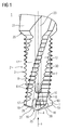
- a Bohrgewindefräser 1 is outlined, which has a, in particular cylindrical, shaft 21 for the tool holder in a machine tool. At the lower end of the shank 21, a work area (chipping part) 2 reduced in diameter is formed, in particular in one piece or by attaching at least one prefabricated part.
- the tool or the Bohrgewindefräser 1 rotates during its use its axis 4, which extends through the shaft 21 and the working area 2 and is generally a longitudinal axis and / or a Hauptenträgheitsachse, in the direction of rotation 15, in this case clockwise or clockwise (right-hand cutting).
- the work area 2 has at its end a drilling area 40 for producing a bore (hole or recess) in a workpiece and at a substantially cylindrically shaped circumference (or envelope) 3, a thread milling area axially offset with respect to the axis 4 30 for generating a thread in the bore produced by the drilling area 40 by thread milling.
- two approximately 180 ° staggered drill main cutting edges 27 and 28 are provided on the front side 16 which run obliquely to the axis 4 forward in a drill tip 25 and two to the drill main cutting edges 27 and 28 respectively at an angle ⁇ of 45
- the chamfer 19 is advantageous in the machining of cast iron materials, but can also be omitted in particular with other materials.
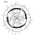
- the Bohrgewindefräser 1 in Gewindefräs Symposium 30 two Fräshuntpane 5 and 6, each consisting of two Frästrack 7 and 8 or 9 and 10.
- the two milling cutters 7 and 8 or 9 and 10 have an angular spacing which is less than 90 °, preferably not more than 88 °, ie the milling cutting edge 8 or 10 following in the direction of tool rotation (cutting direction) 15 follows the preceding milling cutting edge 7 or 9, respectively an angle ⁇ of a maximum of 88 °.
- Preferred values for the angle ⁇ are between 62 ° and 88 °, with a value of 75 ° being particularly preferred.
- the chip space 12 continues at the front up to the Bohrmantelschneide 17 and the main cutting edge 27 and the chip space 11 up to the Bohrmantelschneide 18 and the main cutting edge 28 where it forms the rake surface for the resulting chips during drilling of the workpiece material.
- the two chip spaces 11 and 12 are formed relatively large or bulky, in order to remove the costs incurred during the drilling process comparatively large chips.
- the chip receiving chambers 13 and 14 perform together with the chip spaces 11 and 12 during thread milling the chips. Since the chip receiving chambers 13, 14 are used only for thread milling for chip removal, but not for drilling, they need only accommodate the smaller milling chips and therefore may be made smaller.
- the chip spaces 11 and 12 are determined in terms of their size significantly by the diameter d min1 , which defines the closest to the axis 4 point of the chip spaces 11 and 12, which is also referred to as the core diameter and twice the radius or radial distance from the axis 4 corresponds.
- the diameter d min1 is in particular between 27% and 50% of the outer diameter do of the milling region 30, particularly preferably 43%.
- the smaller chip spaces 13 and 14 are largely determined by the diameter d min2 , which defines the point 4 closest to the axis of these chip spaces 13, 14 (core diameter). Values between 42% and 75% of the outer diameter do of the shaft 2 are provided for the diameter d min2 , with a value of 60% being preferred.
- the chip spaces 11 to 14 are provided as, for example, ground, flutes for discharging chips and formed in the illustrated embodiment twisted, so with a rotation or spiral formation about the axis 4, but can also be straight, i. parallel to the axis 4.
- the respectively formed with the walls of the chip spaces 11 to 14 clamping surfaces on the associated drilling or milling cutters can be flat or curved.
- a point 31 and 32 can be provided at least in the cutting edges associated with the chip spaces 11 and 12, so an additional chamfer, which is flatter to the drill bit 26 out than the rest of the groove.
- the corresponding Ausspitzung the Bohrstirnschneide or Bohrhauptberger 27 and 28 is designed large volume to ensure an unobstructed Bohrspanab Installation.
- the movement of the drill thread milling cutter 1 during drilling comprises a linear axial feed into the workpiece against the axis 4 against the arrow designated a and simultaneous rotation about the axis 4 in the direction of rotation 15, wherein the drill bits 17 and 18 and 27 and 28 of the drilling area 40 continuously are in the cutting engagement in the workpiece.
- the drilling is done according to 1 to 3 nutig and the drill cuttings are discharged through the two chip receiving chambers 11 and 12.
- FIG. 1 and 3 It can be seen that a plurality of milling cutters, for example 7, are arranged as milling teeth of a thread cutting profile 19 over the thread milling area 30, axially or staggered axially relative to the axis 4, for parallel production of a plurality of threads of the thread.
- the cutting teeth or milling cutters 7 to 10 are in each case arranged axially in groups of four at a height or a plane, wherein the axial spacing of the tooth groups corresponds to the thread pitch.
- the number of groups of teeth corresponds to the number of threads to be produced, so that one to one and one-half rotations of the tool in the circular motion sufficient to produce a complete thread.
- a smaller number of cutting teeth in the axial direction or of groups of teeth may also be provided, the smaller number being compensated by an increase in the number of revolutions of the drill thread milling cutter 1 during thread milling.
- primary ridges and secondary ridges are formed, of which the front face (rake face) of the primary ridges and the back face of the secondary ridges have the grooves and the back faces of the primary ridges and the ridges (rake faces) of the secondary ridges milled grooves.
- the secondary tooth webs are each set back axially on the forehead opposite the primary tooth webs. This can be z. B. already done by the Kegelmantelanschliff the Bohrerstirnschneide. By resetting the secondary tooth webs ensures that during drilling the coolant and lubricant, which emerges in the face region of the milling groove, sufficiently penetrates into the drill groove.
- the milling cutters 7, 8, 9 and 10 taper (slightly) in the axial direction a.
- the taper of the milling blades or the outer diameter of the thread milling section 30 is selected in a range of 0.15% for less solid materials such as gray cast iron (GG) materials, that is, one thread length of 15 mm, the difference or difference between the outside diameters at the end of the thread milling section 30 toward the front side and the end of the thread milling section 30 towards the shaft 21 would be 0.0225 mm (or 22.5 ⁇ m).
- the taper is chosen to be greater, in particular in a range between 0.15% and 1%, in particular in one area between 0.15% and 0.5%, and preferably about 0.2%. This taper compensates for the radial displacement of the tool, which is greater for a high strength material than for a less rigid material.
- the taper of the core diameter leads to an increase in the volumes of the chip spaces 11 and 12, which are effective during drilling, and allows for long-chipping materials improved chip removal. This is especially true in steels where due to the elasticity of the drill cuttings, these expand or partially rewind after removal and reshaping or curling at the forehead in the course of the grooves 11 and 12 during removal and in which thus the increase in volume of the flutes this expansion of the chips partially compensated and creates more space for the drill chips.
- the taper or decrease of the core diameter d min1 of the bore clearance spaces 11 and 12 is particularly selected in a range of 0.01 mm to 0.3 mm with respect to an axial length of 10 mm, that is, a percentage difference or decrease or taper of 0 , 1% to 3% in relation to the inside diameter (or: the groove bottom or the deepest point of the drilled grooves) and over the axial length of the drilled grooves.
- the milling chip spaces 13 and 14 preferably remain constant in their cross section and their core diameter d min2 over the axial length.
- a countersink portion 20 At the end remote from the end face 16 of the working area 2 at the transition to the shaft 21 is a countersink portion 20, which is arranged for example at 45 ° and can sink the finished bore.
- the drill thread milling cutter 1 can have a back-ground cylindrical part or section at the end of the milling cutters to remove an incomplete thread.
- the maximum radial distance of the milling cutters 7, 8, 9 and 10 and thus the entire Gewindefräs Suites 30 of the axis 4 is thus smaller by the predetermined radial distance difference t than the maximum radial distance of Bohrmantelconnect 17 and 18 and thus the entire drilling area 40th Mit
- This choice of the given radial distance difference t prevents chips between the milling cutters 7, 8, 9, 10 and the bore inner wall produced by the Bohrmantelconnect 17 and 18 are clamped, which could otherwise lead to breakage of the tool.
- At least the drill main cutting edges and / or the milling cutters has a cutting edge rounding.
- the cutting edge rounding at the drill bits is chosen to be larger or smaller depending on the material to be machined and can be generated by brushing or sandblasting and possibly previous bleed.
- the rounding should on the one hand stabilize the drill main cutting edge and on the other hand support the chip breakage.
- the cutting edges can have an outgoing edge to the outer diameter, that is to say run somewhat curved or rounded. This results in improved chip removal.
- FIG. 1 and 2 shows how the supply of coolant and / or lubricant can be carried out.
- It is a central coolant and / or lubricant channel (cooling and / or lubricant bore) 23 coaxial with the axis 4 in the shaft 21 and the working area 2 incorporated, which branches off at its end into two sub-channels, each in an outlet opening 26 in each one of the smaller chip spaces 13 and 14 open at the front ends. Accordingly, it can of course also be provided that the discharge of coolant and / or lubricant into the chip receiving chambers 11 and 12 takes place.
Landscapes
- Engineering & Computer Science (AREA)
- Mechanical Engineering (AREA)
- Drilling Tools (AREA)
- Milling Processes (AREA)
Applications Claiming Priority (2)
| Application Number | Priority Date | Filing Date | Title |
|---|---|---|---|
| DE102005014422.5A DE102005014422B4 (de) | 2005-03-24 | 2005-03-24 | Bohrgewindefräser |
| EP06005160A EP1704953A1 (fr) | 2005-03-24 | 2006-03-14 | Fraise forante de filetage |
Related Parent Applications (2)
| Application Number | Title | Priority Date | Filing Date |
|---|---|---|---|
| EP06005160.4 Division | 2006-03-14 | ||
| EP06005160A Division EP1704953A1 (fr) | 2005-03-24 | 2006-03-14 | Fraise forante de filetage |
Publications (2)
| Publication Number | Publication Date |
|---|---|
| EP2260965A2 true EP2260965A2 (fr) | 2010-12-15 |
| EP2260965A3 EP2260965A3 (fr) | 2018-07-25 |
Family
ID=36600736
Family Applications (2)
| Application Number | Title | Priority Date | Filing Date |
|---|---|---|---|
| EP10181341.8A Withdrawn EP2260965A3 (fr) | 2005-03-24 | 2006-03-14 | Fraise forante de filetage |
| EP06005160A Withdrawn EP1704953A1 (fr) | 2005-03-24 | 2006-03-14 | Fraise forante de filetage |
Family Applications After (1)
| Application Number | Title | Priority Date | Filing Date |
|---|---|---|---|
| EP06005160A Withdrawn EP1704953A1 (fr) | 2005-03-24 | 2006-03-14 | Fraise forante de filetage |
Country Status (5)
| Country | Link |
|---|---|
| US (1) | US7419339B2 (fr) |
| EP (2) | EP2260965A3 (fr) |
| JP (1) | JP2006263912A (fr) |
| CN (1) | CN1836813B (fr) |
| DE (1) | DE102005014422B4 (fr) |
Cited By (1)
| Publication number | Priority date | Publication date | Assignee | Title |
|---|---|---|---|---|
| EP4230334A1 (fr) * | 2022-02-18 | 2023-08-23 | KOMET Deutschland GmbH | Fraise à fileter |
Families Citing this family (44)
| Publication number | Priority date | Publication date | Assignee | Title |
|---|---|---|---|---|
| US7950880B2 (en) * | 2006-10-18 | 2011-05-31 | Kennametal Inc. | Spiral flute tap |
| US20100260568A1 (en) * | 2007-10-29 | 2010-10-14 | Osg Corporation | Thread milling cutter |
| US20090148250A1 (en) * | 2007-12-05 | 2009-06-11 | Wayne Chappell | Drill Bit |
| US8407891B2 (en) * | 2008-10-15 | 2013-04-02 | GM Global Technology Operations LLC | Method for providing a controlled spark plug orientation in an engine structure |
| JP5301647B2 (ja) * | 2009-02-20 | 2013-09-25 | オーエスジー株式会社 | ドリル付きタップ、およびめねじ加工方法 |
| USD632319S1 (en) * | 2010-02-25 | 2011-02-08 | Gn Tool Co., Ltd. | Endmill |
| DE102010025148A1 (de) | 2010-06-25 | 2012-03-01 | Günter Sperling | Spanabhebendes Werkzeug |
| DE102011001772A1 (de) * | 2010-12-14 | 2012-06-14 | EMUGE-Werk Richard Glimpel GmbH & Co. KG Fabrik für Präzisionswerkzeuge | Gewindeerzeugungswerkzeug zum Herstellen eines Gewindes in einem Werkstück |
| WO2013132665A1 (fr) * | 2012-03-09 | 2013-09-12 | オーエスジー株式会社 | Robinet hélicoïdal |
| KR20150031278A (ko) * | 2012-07-17 | 2015-03-23 | 오에스지 가부시키가이샤 | 스파이럴 탭 |
| USD701255S1 (en) * | 2012-08-08 | 2014-03-18 | Dasan Machineries Co., Ltd. | Double end mill |
| CN102814560B (zh) * | 2012-09-22 | 2015-06-10 | 宁波川景誉机械科技发展有限公司 | 具有内冷却结构的锥度螺纹铣刀 |
| CN103100854A (zh) * | 2012-12-28 | 2013-05-15 | 铜陵市霞飞新材料有限责任公司 | 一次成型沉头螺纹孔加工装置 |
| EP2792443A1 (fr) * | 2013-04-15 | 2014-10-22 | Techno s.r.l. | Fraise pour le taraudage |
| CN104174941A (zh) * | 2013-05-21 | 2014-12-03 | 苏州锑玛精密机械有限公司 | 一种螺纹铣刀 |
| EP2954968B1 (fr) * | 2014-06-13 | 2021-01-20 | Walter Ag | Fraise de filetage |
| USD750674S1 (en) * | 2014-08-01 | 2016-03-01 | Duane C. Dunnahoe | Milling tool |
| AT14275U1 (de) * | 2014-08-06 | 2015-07-15 | Günther Wirth Hartmetallwerkzeuge Gmbh & Co Kg | Fräswerkzeug |
| WO2016045681A1 (fr) * | 2014-09-23 | 2016-03-31 | Danske Vaerktoej Aps | Taraud de filetage |
| JP2016155178A (ja) * | 2015-02-23 | 2016-09-01 | 泰介 森藤 | 回転工具、及び回転工具の製造方法 |
| USD799574S1 (en) * | 2015-03-30 | 2017-10-10 | Technicut Limited | Milling tool |
| US10857601B2 (en) * | 2015-08-18 | 2020-12-08 | Dalian University Of Technology | Sawtooth structure with reversed cutting function and its drill series |
| CN105252089A (zh) * | 2015-11-27 | 2016-01-20 | 上海科弦精密工具有限公司 | 一种高硬度模具钢精密刀具 |
| JP6672332B2 (ja) | 2015-12-02 | 2020-03-25 | オーエスジー株式会社 | 管用テーパねじ加工スパイラルタップ |
| JP6499117B2 (ja) * | 2016-04-08 | 2019-04-10 | トヨタ自動車株式会社 | 雌ねじ加工工具 |
| DE102016009738A1 (de) | 2016-08-10 | 2018-02-15 | Audi Ag | Verfahren sowie Werkzeug zur Erzeugung eines Innengewindes in einer Werkstück-Vorbohrung |
| EP3342518B1 (fr) * | 2016-12-28 | 2019-12-11 | Sandvik Intellectual Property AB | Outil de fraisage ayant des rainures d'écoulement de réfrigérant |
| DE102017102473B4 (de) * | 2017-02-08 | 2025-03-27 | Franken Gmbh & Co. Kg Fabrik Für Präzisionswerkzeuge | Fräswerkzeug, insbesondere Tannenbaumfräser, und Herstellungsverfahren für ein Fräswerkzeug |
| USD882791S1 (en) * | 2018-01-31 | 2020-04-28 | Beijing Smtp Technology Co., Ltd. | Ultrasonic cutter head |
| US10875201B2 (en) | 2018-04-04 | 2020-12-29 | Swanstrom Tools Usa Inc. | Relief guard for hand tools |
| DE102018206545B4 (de) * | 2018-04-27 | 2021-10-14 | Audi Ag | Gewindebohr-Werkzeug und Verfahren zur Erzeugung einer Gewindebohrung |
| DE102018114138A1 (de) * | 2018-06-13 | 2019-12-19 | Botek Präzisionsbohrtechnik Gmbh | Tieflochbohrer mit mehreren Spanformern und Mulden in der Spanfläche |
| DE102018115986A1 (de) * | 2018-07-02 | 2020-01-02 | EMUGE-Werk Richard Glimpel GmbH & Co. KG Fabrik für Präzisionswerkzeuge | Werkzeug zum Erzeugen eines Gewindes |
| WO2020031259A1 (fr) * | 2018-08-07 | 2020-02-13 | 住友電工ハードメタル株式会社 | Foret |
| EP3722035A1 (fr) * | 2019-04-08 | 2020-10-14 | Walter Ag | Dispositif de filetage |
| WO2022032178A1 (fr) | 2020-08-06 | 2022-02-10 | Mate Precision Technologies Inc. | Ensemble étau |
| US11878381B2 (en) | 2020-08-06 | 2024-01-23 | Mate Precision Technologies Inc. | Tooling base assembly |
| USD989136S1 (en) * | 2021-07-27 | 2023-06-13 | Anwiner Technology International Inc | Drill head |
| USD1039933S1 (en) * | 2021-12-20 | 2024-08-27 | William Norton | Driver |
| CN114378379B (zh) * | 2022-01-24 | 2022-12-27 | 江苏正恺电子科技有限公司 | 一种高精度内螺纹用新型钻头及其使用方法 |
| US12350745B2 (en) * | 2023-02-01 | 2025-07-08 | Sumitomo Electric Hardmetal Corp. | Cutting tool |
| CN117884724B (zh) * | 2024-03-14 | 2024-05-31 | 常州市创荣工具制造有限公司 | 一种免打底孔螺纹铣刀 |
| CN119549815B (zh) * | 2024-10-22 | 2025-10-31 | 东风汽车集团股份有限公司 | 刀具规格确定方法、装置、设备以及可读存储介质 |
| CN119973176B (zh) * | 2025-01-06 | 2026-01-06 | 株洲钻石切削刀具股份有限公司 | 一种具有铣削刃的麻花钻 |
Citations (3)
| Publication number | Priority date | Publication date | Assignee | Title |
|---|---|---|---|---|
| US4651374A (en) | 1986-03-17 | 1987-03-24 | Turchan Manuel C | Combined hole making and threading tool |
| US4761844A (en) | 1986-03-17 | 1988-08-09 | Turchan Manuel C | Combined hole making and threading tool |
| WO2004022274A1 (fr) | 2002-08-10 | 2004-03-18 | Felix Leeb | Fraise a fileter |
Family Cites Families (26)
| Publication number | Priority date | Publication date | Assignee | Title |
|---|---|---|---|---|
| DE1106144B (de) * | 1956-11-22 | 1961-05-04 | Friedrich Boehme | Spiralbohrer |
| JPS6244304A (ja) * | 1985-08-20 | 1987-02-26 | Masao Kubota | ドリルのシンニング |
| DE3786096T2 (de) * | 1986-03-13 | 1993-10-14 | Turchan Manuel C | Methode und Werkzeug zum Gewindeschneidbohren. |
| US5413438A (en) * | 1986-03-17 | 1995-05-09 | Turchan; Manuel C. | Combined hole making and threading tool |
| SE456408B (sv) * | 1987-02-10 | 1988-10-03 | Sandvik Ab | Borr- och gengverktyg |
| DE3808797A1 (de) * | 1988-03-16 | 1989-10-05 | Prototyp Werke Gmbh | Gewindefraeser |
| DE3828780A1 (de) * | 1988-08-25 | 1990-03-01 | Schmitt M Norbert Dipl Kaufm D | Bohrgewindefraeser |
| DE3939795A1 (de) * | 1989-12-01 | 1991-06-06 | Schmitt M Norbert Dipl Kaufm D | Verfahren zur herstellung einer gewindebohrung |
| JP2571499Y2 (ja) * | 1992-03-06 | 1998-05-18 | オーエスジー株式会社 | ドリル刃付きねじ切りフライス |
| US5350261A (en) * | 1992-03-12 | 1994-09-27 | Mitsubishi Materials Corporation | Twist drill |
| JP3071466B2 (ja) * | 1993-08-06 | 2000-07-31 | ケンナメタル ヘルテル アクチェンゲゼルシャフト ウェルクツォイゲ ウント ハルトシュトッフェ | ツイストドリル |
| US5678962A (en) * | 1994-09-06 | 1997-10-21 | Makino Inc. | Integral boring and threading tool and method |
| DE4440480C2 (de) * | 1994-11-12 | 1998-09-24 | Felix Leeb | Fräsbohrwerkzeug |
| US6012882A (en) * | 1995-09-12 | 2000-01-11 | Turchan; Manuel C. | Combined hole making, threading, and chamfering tool with staggered thread cutting teeth |
| DE19548199A1 (de) * | 1995-12-22 | 1997-06-26 | Link Johann & Ernst Gmbh & Co | Verfahren zur Herstellung einer Gewindebohrung sowie Werkzeug zur Durchführung eines solchen Verfahrens |
| DE19608185A1 (de) * | 1996-03-04 | 1997-09-11 | Guehring Joerg Dr | Bohrwerkzeug |
| US5709587A (en) * | 1996-03-25 | 1998-01-20 | Kennametal Inc. | Method and apparatus for honing an elongate rotary tool |
| US5733078A (en) * | 1996-06-18 | 1998-03-31 | Osg Corporation | Drilling and threading tool |
| DE19739370A1 (de) * | 1997-09-09 | 1999-03-11 | Schmitt M Norbert Dipl Kaufm D | Gewindefräsbohr-Werkzeug für Werkstoffe höherer Festigkeit |
| US6105467A (en) * | 1998-06-26 | 2000-08-22 | Baker; David A. | Method for preparing a cutting edge on an end mill |
| DE19927386A1 (de) * | 1999-06-16 | 2001-01-04 | Fette Wilhelm Gmbh | Verfahren zur Herstellung einer Gewindebohrung und Werkzeug hierfür |
| US6345941B1 (en) * | 2000-02-23 | 2002-02-12 | Ati Properties, Inc. | Thread milling tool having helical flutes |
| JP2002144125A (ja) * | 2000-08-31 | 2002-05-21 | Mitsubishi Materials Corp | 穴明け工具 |
| JP2003053606A (ja) * | 2001-08-10 | 2003-02-26 | Hitachi Tool Engineering Ltd | 深穴加工用ドリル |
| US7959381B2 (en) * | 2002-06-13 | 2011-06-14 | Kennametal Inc. | Thread milling tool |
| DE20312819U1 (de) * | 2003-08-14 | 2003-10-09 | MK Werkzeug-Service Manfred Krystek e.K., 07318 Saalfeld | Schweißpunktbohrer |
-
2005
- 2005-03-24 DE DE102005014422.5A patent/DE102005014422B4/de not_active Expired - Fee Related
-
2006
- 2006-03-14 EP EP10181341.8A patent/EP2260965A3/fr not_active Withdrawn
- 2006-03-14 EP EP06005160A patent/EP1704953A1/fr not_active Withdrawn
- 2006-03-23 JP JP2006080373A patent/JP2006263912A/ja active Pending
- 2006-03-24 CN CN2006100584484A patent/CN1836813B/zh not_active Expired - Fee Related
- 2006-03-24 US US11/388,471 patent/US7419339B2/en not_active Expired - Fee Related
Patent Citations (3)
| Publication number | Priority date | Publication date | Assignee | Title |
|---|---|---|---|---|
| US4651374A (en) | 1986-03-17 | 1987-03-24 | Turchan Manuel C | Combined hole making and threading tool |
| US4761844A (en) | 1986-03-17 | 1988-08-09 | Turchan Manuel C | Combined hole making and threading tool |
| WO2004022274A1 (fr) | 2002-08-10 | 2004-03-18 | Felix Leeb | Fraise a fileter |
Non-Patent Citations (1)
| Title |
|---|
| "Handbuch der Gewindetechnik und Frastechnik, Herausgeber: EMUGE-FRANKEN", 2004, VERLAG: PUBLICIS CORPORATE PUBLISHING, pages: 354 |
Cited By (2)
| Publication number | Priority date | Publication date | Assignee | Title |
|---|---|---|---|---|
| EP4230334A1 (fr) * | 2022-02-18 | 2023-08-23 | KOMET Deutschland GmbH | Fraise à fileter |
| WO2023156031A1 (fr) * | 2022-02-18 | 2023-08-24 | Ceratizit Besigheim Gmbh | Fraise à fileter |
Also Published As
| Publication number | Publication date |
|---|---|
| DE102005014422A1 (de) | 2006-09-28 |
| EP1704953A1 (fr) | 2006-09-27 |
| DE102005014422B4 (de) | 2019-10-24 |
| CN1836813A (zh) | 2006-09-27 |
| US20060216125A1 (en) | 2006-09-28 |
| US7419339B2 (en) | 2008-09-02 |
| JP2006263912A (ja) | 2006-10-05 |
| CN1836813B (zh) | 2012-05-30 |
| EP2260965A3 (fr) | 2018-07-25 |
Similar Documents
| Publication | Publication Date | Title |
|---|---|---|
| DE102005014422B4 (de) | Bohrgewindefräser | |
| EP0103235B1 (fr) | Outil de perçage | |
| EP2651585B1 (fr) | Outil de formage de filet pour produire un filet sur une pièce | |
| EP1864737B1 (fr) | Outil d'usinage par enlevement de copeaux | |
| EP2237913B9 (fr) | Outil de perçage et pointe correspondante | |
| DE102011106416B4 (de) | Bohr-Reib-Werkzeug | |
| EP1669149B1 (fr) | Outil et procédé pour produire un pas de vis dans une pièce | |
| EP2229254B1 (fr) | Outil d'alésage de pièces par enlèvement de matière | |
| EP1832371B1 (fr) | Outil de combinaison doté d'un évidement frontal | |
| EP2550126B1 (fr) | Alésoir avec canaux de refroidissement | |
| DE2145795A1 (de) | Schneidwerkzeug | |
| EP3085481A1 (fr) | Outil combiné de perçage et de chanfreinage | |
| EP2888066B1 (fr) | Foret à une lèvre pour trou profond | |
| WO2016020047A1 (fr) | Outil de fraisage | |
| EP1511590A1 (fr) | Fraise a rayon de segment racleur | |
| EP1314506B1 (fr) | Outil de taraudage | |
| WO2018011314A1 (fr) | Foret étagé | |
| DE102005022503B4 (de) | Werkzeug und Verfahren zur Erzeugung eines Gewindes | |
| EP2113325A1 (fr) | Outil de forage cylindrique | |
| WO2011000355A1 (fr) | Foret pour forage profond | |
| DE112008004051T5 (de) | Spiralgewindebohrer | |
| EP3132875A1 (fr) | Outil de fraisage | |
| DE19735024A1 (de) | Bohrer für zusätzliche Rückseitenbearbeitung | |
| EP3093089A1 (fr) | Outil de rotation | |
| DE102005019921A1 (de) | Werkzeug und Verfahren zur Erzeugung oder Nachbearbeitung eines Gewindes |
Legal Events
| Date | Code | Title | Description |
|---|---|---|---|
| PUAI | Public reference made under article 153(3) epc to a published international application that has entered the european phase |
Free format text: ORIGINAL CODE: 0009012 |
|
| AC | Divisional application: reference to earlier application |
Ref document number: 1704953 Country of ref document: EP Kind code of ref document: P |
|
| AK | Designated contracting states |
Kind code of ref document: A2 Designated state(s): AT BE BG CH CY CZ DE DK EE ES FI FR GB GR HU IE IS IT LI LT LU LV MC NL PL PT RO SE SI SK TR |
|
| PUAL | Search report despatched |
Free format text: ORIGINAL CODE: 0009013 |
|
| AK | Designated contracting states |
Kind code of ref document: A3 Designated state(s): AT BE BG CH CY CZ DE DK EE ES FI FR GB GR HU IE IS IT LI LT LU LV MC NL PL PT RO SE SI SK TR |
|
| RIC1 | Information provided on ipc code assigned before grant |
Ipc: B23G 5/18 20060101AFI20180618BHEP |
|
| STAA | Information on the status of an ep patent application or granted ep patent |
Free format text: STATUS: REQUEST FOR EXAMINATION WAS MADE |
|
| 17P | Request for examination filed |
Effective date: 20190125 |
|
| RBV | Designated contracting states (corrected) |
Designated state(s): AT BE BG CH CY CZ DE DK EE ES FI FR GB GR HU IE IS IT LI LT LU LV MC NL PL PT RO SE SI SK TR |
|
| STAA | Information on the status of an ep patent application or granted ep patent |
Free format text: STATUS: THE APPLICATION IS DEEMED TO BE WITHDRAWN |
|
| 18D | Application deemed to be withdrawn |
Effective date: 20221001 |