EP2261002A1 - Dispositif de chauffage - Google Patents
Dispositif de chauffage Download PDFInfo
- Publication number
- EP2261002A1 EP2261002A1 EP10005261A EP10005261A EP2261002A1 EP 2261002 A1 EP2261002 A1 EP 2261002A1 EP 10005261 A EP10005261 A EP 10005261A EP 10005261 A EP10005261 A EP 10005261A EP 2261002 A1 EP2261002 A1 EP 2261002A1
- Authority
- EP
- European Patent Office
- Prior art keywords
- heat
- heater
- injection molding
- nozzle
- thermally conductive
- Prior art date
- Legal status (The legal status is an assumption and is not a legal conclusion. Google has not performed a legal analysis and makes no representation as to the accuracy of the status listed.)
- Withdrawn
Links
- 238000010438 heat treatment Methods 0.000 title claims description 43
- 239000000463 material Substances 0.000 claims abstract description 92
- 238000001746 injection moulding Methods 0.000 claims abstract description 70
- OKTJSMMVPCPJKN-UHFFFAOYSA-N Carbon Chemical compound [C] OKTJSMMVPCPJKN-UHFFFAOYSA-N 0.000 claims abstract description 13
- 229910002804 graphite Inorganic materials 0.000 claims abstract description 13
- 239000010439 graphite Substances 0.000 claims abstract description 13
- 238000000926 separation method Methods 0.000 claims description 5
- 230000009969 flowable effect Effects 0.000 description 13
- 238000007789 sealing Methods 0.000 description 12
- 239000004020 conductor Substances 0.000 description 7
- 239000000243 solution Substances 0.000 description 5
- 230000032258 transport Effects 0.000 description 5
- 230000002349 favourable effect Effects 0.000 description 4
- 229910001315 Tool steel Inorganic materials 0.000 description 3
- 238000010276 construction Methods 0.000 description 2
- 230000000694 effects Effects 0.000 description 2
- 238000002347 injection Methods 0.000 description 2
- 239000007924 injection Substances 0.000 description 2
- 230000001681 protective effect Effects 0.000 description 2
- 230000009286 beneficial effect Effects 0.000 description 1
- 150000001875 compounds Chemical class 0.000 description 1
- 210000003746 feather Anatomy 0.000 description 1
- 239000008187 granular material Substances 0.000 description 1
- 238000009413 insulation Methods 0.000 description 1
- 239000007788 liquid Substances 0.000 description 1
- 238000004519 manufacturing process Methods 0.000 description 1
- 238000000034 method Methods 0.000 description 1
- 230000000149 penetrating effect Effects 0.000 description 1
- 230000008092 positive effect Effects 0.000 description 1
Images




Classifications
-
- B—PERFORMING OPERATIONS; TRANSPORTING
- B29—WORKING OF PLASTICS; WORKING OF SUBSTANCES IN A PLASTIC STATE IN GENERAL
- B29C—SHAPING OR JOINING OF PLASTICS; SHAPING OF MATERIAL IN A PLASTIC STATE, NOT OTHERWISE PROVIDED FOR; AFTER-TREATMENT OF THE SHAPED PRODUCTS, e.g. REPAIRING
- B29C45/00—Injection moulding, i.e. forcing the required volume of moulding material through a nozzle into a closed mould; Apparatus therefor
- B29C45/17—Component parts, details or accessories; Auxiliary operations
- B29C45/26—Moulds
- B29C45/27—Sprue channels ; Runner channels or runner nozzles
- B29C45/278—Nozzle tips
-
- B—PERFORMING OPERATIONS; TRANSPORTING
- B29—WORKING OF PLASTICS; WORKING OF SUBSTANCES IN A PLASTIC STATE IN GENERAL
- B29C—SHAPING OR JOINING OF PLASTICS; SHAPING OF MATERIAL IN A PLASTIC STATE, NOT OTHERWISE PROVIDED FOR; AFTER-TREATMENT OF THE SHAPED PRODUCTS, e.g. REPAIRING
- B29C45/00—Injection moulding, i.e. forcing the required volume of moulding material through a nozzle into a closed mould; Apparatus therefor
- B29C45/17—Component parts, details or accessories; Auxiliary operations
- B29C45/26—Moulds
- B29C45/27—Sprue channels ; Runner channels or runner nozzles
- B29C45/2737—Heating or cooling means therefor
-
- B—PERFORMING OPERATIONS; TRANSPORTING
- B29—WORKING OF PLASTICS; WORKING OF SUBSTANCES IN A PLASTIC STATE IN GENERAL
- B29C—SHAPING OR JOINING OF PLASTICS; SHAPING OF MATERIAL IN A PLASTIC STATE, NOT OTHERWISE PROVIDED FOR; AFTER-TREATMENT OF THE SHAPED PRODUCTS, e.g. REPAIRING
- B29C45/00—Injection moulding, i.e. forcing the required volume of moulding material through a nozzle into a closed mould; Apparatus therefor
- B29C45/17—Component parts, details or accessories; Auxiliary operations
- B29C45/26—Moulds
- B29C45/27—Sprue channels ; Runner channels or runner nozzles
- B29C45/2737—Heating or cooling means therefor
- B29C45/2738—Heating or cooling means therefor specially adapted for manifolds
-
- B—PERFORMING OPERATIONS; TRANSPORTING
- B29—WORKING OF PLASTICS; WORKING OF SUBSTANCES IN A PLASTIC STATE IN GENERAL
- B29C—SHAPING OR JOINING OF PLASTICS; SHAPING OF MATERIAL IN A PLASTIC STATE, NOT OTHERWISE PROVIDED FOR; AFTER-TREATMENT OF THE SHAPED PRODUCTS, e.g. REPAIRING
- B29C45/00—Injection moulding, i.e. forcing the required volume of moulding material through a nozzle into a closed mould; Apparatus therefor
- B29C45/17—Component parts, details or accessories; Auxiliary operations
- B29C45/72—Heating or cooling
- B29C45/73—Heating or cooling of the mould
- B29C45/7331—Heat transfer elements, e.g. heat pipes
-
- B—PERFORMING OPERATIONS; TRANSPORTING
- B29—WORKING OF PLASTICS; WORKING OF SUBSTANCES IN A PLASTIC STATE IN GENERAL
- B29C—SHAPING OR JOINING OF PLASTICS; SHAPING OF MATERIAL IN A PLASTIC STATE, NOT OTHERWISE PROVIDED FOR; AFTER-TREATMENT OF THE SHAPED PRODUCTS, e.g. REPAIRING
- B29C45/00—Injection moulding, i.e. forcing the required volume of moulding material through a nozzle into a closed mould; Apparatus therefor
- B29C45/17—Component parts, details or accessories; Auxiliary operations
- B29C45/26—Moulds
- B29C45/27—Sprue channels ; Runner channels or runner nozzles
- B29C2045/2777—Means for controlling heat flow or temperature distribution in the nozzle
-
- B—PERFORMING OPERATIONS; TRANSPORTING
- B29—WORKING OF PLASTICS; WORKING OF SUBSTANCES IN A PLASTIC STATE IN GENERAL
- B29C—SHAPING OR JOINING OF PLASTICS; SHAPING OF MATERIAL IN A PLASTIC STATE, NOT OTHERWISE PROVIDED FOR; AFTER-TREATMENT OF THE SHAPED PRODUCTS, e.g. REPAIRING
- B29C45/00—Injection moulding, i.e. forcing the required volume of moulding material through a nozzle into a closed mould; Apparatus therefor
- B29C45/17—Component parts, details or accessories; Auxiliary operations
- B29C45/26—Moulds
- B29C45/27—Sprue channels ; Runner channels or runner nozzles
- B29C45/278—Nozzle tips
- B29C2045/2787—Nozzle tips made of at least 2 different materials
Definitions
- the invention relates to a heating device for injection molding apparatus according to the preamble of claim 1 and the use of an anisotropic material for directional heat transfer in a heating device of an injection molding apparatus.
- Injection molding devices are usually used to supply a flowable plastic compound at a predeterminable temperature under high pressure to a separable tool block (mold cavity).
- Such an injection molding apparatus usually comprises at least one distributor and at least one injection molding nozzle. So that the mostly hot mass within the device - especially within a flow channel formed in the device - does not cool prematurely, usually a heater is provided which concentrically surrounds a material pipe or the flow channel formed therein and the liquid plastic as far as possible to the top of To keep injection molding nozzles in at a constant temperature. A thermal separation between the hot injection molding device and colder tool ensures that the device does not freeze and at the same time the tool (mold cavity) is not heated.
- the material costs can be very high, especially if the nozzle tip not only to ensure optimum heat supply, but at the same time should also be as wear-resistant as possible.
- the heat transfer in these solutions is often not optimal.
- the invention provides that the heat-conducting member is made of an anisotropic material.
- a first advantage of the solution according to the invention is that the heat can be transported by means of the heat-conducting element in places that can not be directly in contact with the heater, for example, due to limited space.
- the material of the heat-conducting element is anisotropic - preferably thermally anisotropic - then the orientation of the material of the heat-conducting element can also be used to achieve a directed heat transfer.
- the thermally conductive element then transports the heat in a particular direction particularly well and effectively, not in at least one other.
- the anisotropic material has at least one high-heat-conducting direction.
- the heating is connected by a thermally conductive connection directly or indirectly with the thermally conductive element such that the heat in the highly heat-conducting direction through the heat-conducting Element is passed.
- the thermally conductive element is fed in this way from its one end with the heat of the heater. It then transports these to his other End to the place where the heat to develop their effect and to serve to keep the flowable mass in the injection molding at the optimum temperature.
- This is particularly advantageous, since thus also areas of the injection molding nozzle can be supplied with heat that, for example, for reasons of space can not be directly surrounded by a heater. For example, the tip of a nozzle mouthpiece can be supplied directly with heat. Overall, the generated heat of the heater can be used more effectively in this way.
- the thermally conductive element according to the invention it is no longer necessary to manufacture the entire nozzle mouthpiece - as known from the prior art - from a highly heat-conductive material. This is particularly advantageous since, in particular, the nozzle mouthpiece and the nozzle tip are exposed to high wear during normal operation of the injection molding apparatus and are therefore usually preferably made of a wear-resistant material. However, a material that satisfies both requirements - namely being highly heat-conductive and wear-resistant at the same time - is generally very expensive. With the help of the heating device according to the invention, however, components which are exposed to high wear, can now be produced inexpensively from a common wear-resistant tool steel. In these components, a thermally conductive element according to the invention can then be used, which transports the heat of a heater targeted and directed to the desired areas of the components to be heated.
- thermally conductive element can be embedded in a part of the injection molding device.
- the heat-conducting element is in direct contact with the heating in the highly heat-conducting direction.
- the heat-conducting element is arranged in spatial separation from the heater.
- the heat-conducting element is in direct contact with the heating, the heat is conducted directly into the heat-conducting element in the highly heat-conducting direction by a heat-conducting connection, which is formed by the contact surface between the two components.
- the part of the injection molding device forming the connection between the heating and the heat-conducting element is different from the part of the injection molding device in which the heat-conducting element is embedded.
- the heat-conducting element is applied to a part of the injection molding apparatus.
- the space available for the attachment of a heating space is limited.
- the heating can now be arranged at a remote location and the heat can be transported by means of thermally conductive elements to the destination, which are arranged, for example, on the outside of a material pipe or between distributor plates.
- the anisotropic material has at least one highly heat-conducting direction and if the anisotropic material in at least one direction, preferably the highly heat-conducting direction, a thermal conductivity of more than 500 W / mK, preferably more than 1000 W / mK, more preferably more than 1500 W / mK.
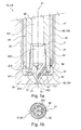
- the in Fig. 1a It has a nozzle body 40, consisting of a material pipe 41 and a nozzle mouthpiece 42 inserted into the lower end of the material pipe 41.
- a material-carrying nozzle tip 43 is formed on the nozzle mouthpiece 42.
- the injection molding nozzle 110 is formed with a heating device 130 according to the invention.
- This consists of a heater 60 and a thermally conductive element 50.
- the heater 60 is, for example, a thick film heater, which is applied to a support tube.
- other conventional constructions of the heater such as a heating coil integrated into a carrier element, are also conceivable.
- the heater 60 is pushed onto the material pipe 41.
- the thermally conductive element 50 is a rod made of pyrolytic or thermopyrolytic graphite, which is integrated in a recess 431 of the nozzle tip 43.
- the thermally conductive element 50 has at its one end a contact region 51 at which it is in contact with the material pipe 41. At its other end, it forms a contact tip 52 with the material of the nozzle tip 43.
- the nozzle tip 43 may be formed with three sections 203 of the flow channel 20, which extend away from the actual tip to the outside.
- the thermally conductive member 50 is disposed so as to conduct the heat straight inward toward the tip.
- three heat-conducting elements 50 are arranged between the three sections 203 of the flow channel 20 such that the contact tips 52 meet in the middle of the nozzle tip 43.
- the highly anisotropic graphite rod is oriented in such a way that it is highly heat-conductive in the direction R, which runs between the contact region 51 with the material pipe 41 and the contact tip 52. Consequently, the heat-conducting element 50 in this direction has a thermal conductivity of more than 1000 W / mK, with a use of thermopyrolytic graphite even more than 1500 W / mK.
- the heat of the material tube 41 brought to the optimum temperature by the heater 60 is absorbed in this way at the contact region 51 by the heat-conducting element 50 and conducted directly to the contact tip 52. There, the heat is released almost without loss of the material of the nozzle tip 43.
- the nozzle tip 42 heats up in particular in the region of the tip 432. As a result, the flowable mass is maintained over the entire flow channel 20 away into the particularly critical region 204 between the injection molding die 110 and mold cavity 30 at the optimum temperature for processing. At the same time eliminates the need for the nozzle orifice 42 or at least the nozzle tip 43 made of a highly heat conductive material to finished.
- the nozzle tip 43 - as is customary, for example, for material pipe 41 and manifold 120 - is manufactured from a conventional tool steel. This is usually much more wear-resistant and less expensive than corresponding highly heat-conductive materials.
- the heating device 130 offers, as a great advantage, a thermally conductive element 50 made of an anisotropic material, with the aid of which a nozzle mouthpiece 42 can be used, which can be manufactured from a cost-effective wear-resistant material and which still provides optimal temperature control up to the outermost portion of the nozzle tip 43 is reached.
- the material pipe 41 forms a connection V according to the invention between the heater 60 and the thermally conductive element 50, and the heater 60 is therefore indirectly in contact with the thermally conductive element 50.
- the nozzle body 40 is arranged in the housing 70 of the injection molding nozzle 110.
- This has a material pipe 41 on the lower region of an end piece 42 'with at least one, preferably a plurality of nozzle tips 43' is placed.
- the end piece 42 ' is secured by means of the support and sealing ring 93' on the material pipe.
- the flow channel 20 begins at an inlet opening 21. There it can be fed for example by a flow channel of a distributor according to the invention. Subsequent to the inlet opening 21, the flow channel 20 in the material pipe 41 has a section 201 which opens directly into the region 204 of the flow channel 20 between the injection molding nozzle 110 and the mold gate 31. The flowable mass flows around the nozzle tips 43 'and passes from there to the mold gate 31 through the outlet opening 22 of the flow channel 20 in the (not shown) mold.
- a thermally conductive element 50 is integrated in the end piece 42 'for each nozzle tip 43'.
- the end piece 42 ' has for this purpose in the region of each nozzle tip 43' an angular recess 431 '.
- the thermally conductive element 50 in the simplest case of two pins 501, 502 consists.
- Each of the pins 501, 502 is inserted into a leg of the angular recess 431 ', so that the pins 501, 502 abut one another at the apex and have a contact surface 53.
- the first pin 501 is also in contact with the heater 60 in a region 51, the second pin 502 in a region 52 with the tip 432 of the nozzle tip 43 '.
- the thermally conductive element 50 is made of a thermally anisotropic material which is highly thermally conductive in the direction which runs between the contact regions 51, 52 and the contact surface 53.
- the thermally conductive element 50 in this direction - if it is for example a pyrolytic graphite - has a thermal conductivity of over 1000 W / mK, with a use of thermopyrolytic graphite even more than 1500 W / mK.
- the heat of the heater 60 is received in this way at the contact area 52 directly through the thermally conductive element 50, namely by the first pin 501, passed to the contact surface 53 and there transferred to the second pin 502. This conducts the heat to the contact region 52 and thus heats the tip 432 of the nozzle tip 43 'most effectively.
- the heat from the heater 60 is transferred to the nozzle tip 43 'with virtually no losses, without the nozzle tip 43' having to be made of a highly heat-conductive material.
- the nozzle tip 43 ' is made of a conventional tool steel. This is usually much more wear-resistant and less expensive than corresponding highly heat-conductive materials.
- the thermally conductive element 50 consists of a continuous angular piece.
- the heat can be taken not only directly from the heater 60, but also from the neck portion 421 of the end piece 42 ', which is also in contact with the heater 60. The heat can then be transmitted via the contact region 54 between the neck region 421 and the thermally conductive element 50.
- the angular recess 431 ' is not filled with a pin, but with a granulate of the desired material.
- FIG. 3 Sheath of a nozzle mouthpiece 42 shown, which is inserted into the lower end of a material pipe 41.
- the flow channel 20 has a section 201 in the material pipe 41, a section 202 in the nozzle mouthpiece 42 and a region 204 between the injection molding nozzle 110 and the mold gate 31.
- the mold gate 31 is closable in this example by means of a valve pin 80.
- the flowable mass is to be kept here to the area 204 through the nozzle mouthpiece 42 at the optimum temperature, so it is necessary that the nozzle mouthpiece 42 itself is also supplied as well as possible with heat.
- the invention solves this first, in which, as in the previous embodiments in the interior of the housing 70, a heater 60 is disposed on the material pipe 41.
- a heater 60 is disposed on the material pipe 41.
- the thermally conductive element 50 This surrounds the inserted in the material pipe 41 neck portion 421 of the nozzle mouthpiece. This can be both a complete sheathing and partially inserted pins or strips of a thermally anisotropic material.
- the thermally conductive element 50 rests on the one hand on a shoulder 411 in the material pipe, so that there a first contact region 51 is formed.
- the thermally conductive element 50 can form a second contact region 52 with a flange shoulder 424 of the nozzle orifice 42.
- the highly heat-conducting direction of the anisotropic material now proceeds in the direction from the first contact region 51 to the second contact region 52, in particular the lower region 426 of the nozzle mouthpiece 42 projecting from the injection nozzle 110 is well supplied with heat.
- the nozzle mouthpiece 42 can be made of a wear-resistant material without regard to any heat conduction properties.
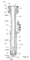
- the inventive thermally conductive element 50 of a heating device 130 according to the invention can also be arranged in the region of the material pipe 41.
- the heating of the material pipe 41 can thus be optimized in such a way that, on the one hand, a uniform heat distribution along the entire material pipe 41 is reached, and on the other hand, as little space is claimed by the heater 60.
- a heating device 130 is provided for this purpose, in which a heater 60 is arranged on the material pipe 41 in the lower region 412 of the injection molding nozzle 110.
- This heater 60 is in contact with a thermally conductive element 50 arranged around the upper region 413 of the material pipe 41 in a contact region 55.
- the thermally conductive element 50 in turn conducts the heat most effectively to a contact region 56 which is formed between the thermally conductive element 50 and the head 44 of the material tube 41.
- the material pipe 41 is supplied optimally with heat up to the head 44, without the immediate arrangement of a heater 60 in this upper region 413 is absolutely necessary. This has a positive effect on the space requirement of the injection molding nozzle 110. This can be made significantly slimmer overall.
- Fig. 5 illustrated embodiment is different from the one described above Fig. 4 merely in that between the thermally conductive element 50 and the head 44th the material pipe 41 additionally a further heater 61 is arranged. Again, the heat of the heaters 60, 61 - as shown above - used very effectively and heat peaks are effectively avoided, especially in the central region 414 of the material tube 41. Thus, the flowable mass along the entire formed in the material pipe 41 portion 201 of the flow channel 20 can be maintained at a uniform and optimal temperature.
- thermally conductive element 50 on the material pipe 41 again different possibilities are conceivable. So can as in Fig. 6a shown strips of a material according to the invention on the outside of the material tube 41 may be applied. It is also conceivable that the material pipe 41, as in Fig. 6b shown in the region is tapered, in which the thermally conductive element 50 is to be arranged. The thermally conductive element 50 can then be introduced into the taper 45, for example in the form of a jacket with the material according to the invention.
- a plurality of injection molding nozzle 110 is arranged on a manifold 120.
- the distributor 120 may be equipped with a heater 60. On the one hand, this supplies the portion 205 of the flow channel 20 which is formed in the distributor. On the other hand, the heat is also distributed therefrom along the nozzle bodies of the injection molding nozzles 110. Thermally conductive elements 50 can then be attached to the material pipes 41 of the injection molding nozzles 110. These transport the heat generated by the heater 60 then most space-saving and effective to the area of the nozzle tips 43 of the injection molding 110. At the same time, it is conceivable that the thermally conductive elements 50 can prevent by their poor thermal conductivity across the highly heat-conductive direction that the heat of the nozzle body to the outside get lost.
- a heating device 130 has a plurality of thermally conductive elements 50, both in the region of the nozzle tips 43, 43 '- in the FIGS. 1 to 3 shown - and at the same time in the region of the material pipe 41 and / or in the region of the manifold 120 are arranged.
- the heat-conducting member 50 advantageously made of an anisotropic material is made.
- the anisotropic material has at least one highly heat-conducting direction, wherein the thermal conductivity in the highly heat-conducting direction is more than 500 W / mK, preferably more than 1000 W / mK, particularly preferably more than 1500 W / mK.
- the anisotropic material is a pyrolytic graphite, preferably a thermo-pyrolytic graphite.
- the heater 60 is directly or indirectly connected to the thermally conductive member 50 by a thermally conductive connection V such that the heat is conducted through the thermally conductive member 50 in the high heat conducting direction.
- the heat-conducting element (50) can be embedded in a part of the injection molding device.
- an anisotropic material for directional heat transfer in a heater 130 of an injection molding apparatus is particularly advantageous when the anisotropic material has at least one high heat conducting direction, wherein the anisotropic material in at least one direction, preferably the high heat conducting direction, a thermal conductivity of more than 500 W / mK, preferably more than 1000 W / mK, more preferably more than 1500 W / mK.
Landscapes
- Engineering & Computer Science (AREA)
- Manufacturing & Machinery (AREA)
- Mechanical Engineering (AREA)
- Physics & Mathematics (AREA)
- Thermal Sciences (AREA)
- Injection Moulding Of Plastics Or The Like (AREA)
- Moulds For Moulding Plastics Or The Like (AREA)
Applications Claiming Priority (1)
| Application Number | Priority Date | Filing Date | Title |
|---|---|---|---|
| DE102009025164A DE102009025164A1 (de) | 2009-06-12 | 2009-06-12 | Heizvorrichtung |
Publications (1)
| Publication Number | Publication Date |
|---|---|
| EP2261002A1 true EP2261002A1 (fr) | 2010-12-15 |
Family
ID=42710739
Family Applications (1)
| Application Number | Title | Priority Date | Filing Date |
|---|---|---|---|
| EP10005261A Withdrawn EP2261002A1 (fr) | 2009-06-12 | 2010-05-20 | Dispositif de chauffage |
Country Status (2)
| Country | Link |
|---|---|
| EP (1) | EP2261002A1 (fr) |
| DE (1) | DE102009025164A1 (fr) |
Families Citing this family (3)
| Publication number | Priority date | Publication date | Assignee | Title |
|---|---|---|---|---|
| DE102013102925B4 (de) | 2013-03-21 | 2016-02-11 | Günther Heisskanaltechnik Gmbh | Spritzgießdüse mit zweiteiligem Materialrohr |
| DE102017110298A1 (de) * | 2017-05-11 | 2018-11-15 | Günther Heisskanaltechnik Gmbh | Einsatz zur Verwendung in einer Spritzgießdüse und Spritzgießdüse mit einem solchen Einsatz |
| DE202020102063U1 (de) | 2020-04-15 | 2020-05-18 | Türk & Hillinger GmbH | Spannbare elektrische Heizvorrichtung |
Citations (10)
| Publication number | Priority date | Publication date | Assignee | Title |
|---|---|---|---|---|
| DE3206157A1 (de) * | 1982-02-20 | 1983-09-01 | Wolfgang Prof. Dipl.-Ing. 8201 Hochstätt Zimmermann | Auskleidung fuer kuststoff-verarbeitende maschinen, insbesondere spritzguss- oder extrusionsmaschinen und verfahren zu ihrer herstellung |
| EP0099089A2 (fr) * | 1982-07-12 | 1984-01-25 | Jobst Ulrich Gellert | Joint de buse pour moulage par injection et son procédé de fabrication |
| US5098280A (en) * | 1990-09-26 | 1992-03-24 | Panos Trakas | Sprue bushing with displaceable gating needle |
| DE29507848U1 (de) | 1995-05-12 | 1995-07-27 | Watlow Electric GmbH, 76709 Kronau | Heizvorrichtung für einen Strömungskanal |
| JPH10156832A (ja) * | 1996-11-28 | 1998-06-16 | Matsushita Electric Ind Co Ltd | 熱伝導制御装置及びこの装置を用いた樹脂成形金型装置 |
| DE10255938A1 (de) * | 2001-11-29 | 2003-06-12 | Mold Masters Ltd | Gering beabstandete Düse mit einem thermisch leitfähigen Einsatz für eine Spritzgießvorrichtung |
| WO2005018906A1 (fr) | 2003-08-13 | 2005-03-03 | Günther Heisskanaltechnik Gmbh | Filiere de moulage par injection |
| EP1612025A1 (fr) * | 2004-07-02 | 2006-01-04 | SFR Formenbau GmbH | Buse d'injection pour guider une matière fondue dans un moule d'injection de matière plastique |
| DE102006049667A1 (de) | 2006-10-18 | 2008-04-24 | Günther Heisskanaltechnik Gmbh | Elektrische Heizeinrichtung für Heißkanalsysteme |
| JP2009202348A (ja) * | 2008-02-26 | 2009-09-10 | Panasonic Corp | 金型装置 |
Family Cites Families (4)
| Publication number | Priority date | Publication date | Assignee | Title |
|---|---|---|---|---|
| GB8715708D0 (en) * | 1987-07-03 | 1987-08-12 | Chloride Silent Power Ltd | Batteries |
| WO1997002129A1 (fr) * | 1995-06-30 | 1997-01-23 | Christian Stern | Buse de moulage par injection de matieres plastiques |
| EP1148985B1 (fr) * | 1999-02-04 | 2002-11-20 | Christian René Stern | Buse pour le moulage par injection des matieres plastiques |
| DE102007051570A1 (de) * | 2007-10-29 | 2009-04-30 | Austrian Research Centers Gmbh | Verfahren zur Herstellung eines Verbundwerkstoffs sowie Verbundwerkstoff, Verbundwerkstoffkörper und Anschlussvorrichtung |
-
2009
- 2009-06-12 DE DE102009025164A patent/DE102009025164A1/de not_active Withdrawn
-
2010
- 2010-05-20 EP EP10005261A patent/EP2261002A1/fr not_active Withdrawn
Patent Citations (10)
| Publication number | Priority date | Publication date | Assignee | Title |
|---|---|---|---|---|
| DE3206157A1 (de) * | 1982-02-20 | 1983-09-01 | Wolfgang Prof. Dipl.-Ing. 8201 Hochstätt Zimmermann | Auskleidung fuer kuststoff-verarbeitende maschinen, insbesondere spritzguss- oder extrusionsmaschinen und verfahren zu ihrer herstellung |
| EP0099089A2 (fr) * | 1982-07-12 | 1984-01-25 | Jobst Ulrich Gellert | Joint de buse pour moulage par injection et son procédé de fabrication |
| US5098280A (en) * | 1990-09-26 | 1992-03-24 | Panos Trakas | Sprue bushing with displaceable gating needle |
| DE29507848U1 (de) | 1995-05-12 | 1995-07-27 | Watlow Electric GmbH, 76709 Kronau | Heizvorrichtung für einen Strömungskanal |
| JPH10156832A (ja) * | 1996-11-28 | 1998-06-16 | Matsushita Electric Ind Co Ltd | 熱伝導制御装置及びこの装置を用いた樹脂成形金型装置 |
| DE10255938A1 (de) * | 2001-11-29 | 2003-06-12 | Mold Masters Ltd | Gering beabstandete Düse mit einem thermisch leitfähigen Einsatz für eine Spritzgießvorrichtung |
| WO2005018906A1 (fr) | 2003-08-13 | 2005-03-03 | Günther Heisskanaltechnik Gmbh | Filiere de moulage par injection |
| EP1612025A1 (fr) * | 2004-07-02 | 2006-01-04 | SFR Formenbau GmbH | Buse d'injection pour guider une matière fondue dans un moule d'injection de matière plastique |
| DE102006049667A1 (de) | 2006-10-18 | 2008-04-24 | Günther Heisskanaltechnik Gmbh | Elektrische Heizeinrichtung für Heißkanalsysteme |
| JP2009202348A (ja) * | 2008-02-26 | 2009-09-10 | Panasonic Corp | 金型装置 |
Also Published As
| Publication number | Publication date |
|---|---|
| DE102009025164A1 (de) | 2010-12-30 |
Similar Documents
| Publication | Publication Date | Title |
|---|---|---|
| EP2177338B1 (fr) | Elément de chauffage tubulaire doté d'un capteur de température | |
| EP2177339B1 (fr) | Buse de moulage par injection | |
| DE60319637T2 (de) | Mit Gewinde versehenes abnehmbares Heizelement für eine Heisskanal-Düse | |
| WO2008067883A1 (fr) | Buse à canal chaud avec capteur de température | |
| DE19618959B4 (de) | Seitenanguß-Spritzgießvorrichtung mit radial angebrachten Angußeinsätzen | |
| DE10201830A1 (de) | Düsenende für eine Spritzgussdüse mit mehreren Spitzen | |
| DE69619362T2 (de) | Spritzgiesssystem und Erhitzungsaufbau zur Verwendung in einem derartigen System | |
| DE10353696B4 (de) | Mikrodüse mit Wärmeleitvorrichtung | |
| DE2539785C3 (de) | Heißkanalspritzdüse | |
| EP2303539A2 (fr) | Buse d'injection pour moule d'injection | |
| DE102011010546B4 (de) | Elektrische Heizvorrichtung | |
| EP2261002A1 (fr) | Dispositif de chauffage | |
| EP2026946B1 (fr) | Buse à canal chaud devant être disposée dans un outil de moulage par injection | |
| DE102008055640A1 (de) | Heißkanaldüse | |
| WO2009071157A2 (fr) | Buse de moulage par injection | |
| EP2260998A1 (fr) | Dispositif de moulage par injection, buse de moulage par injection et distributeur | |
| EP2781332B1 (fr) | Buse de moulage par injection dotée d'un tube de matériau en deux parties | |
| EP2386402B1 (fr) | Buse à canal chaud et outil de moulage par injection doté d'une buse à canal chaud | |
| DE3538206A1 (de) | Warmspritzduese zur verwendung mit einer pressform zum eingusslosen spritzen von kunststoffmaterial | |
| DE202007001789U1 (de) | Spritzgießdüse | |
| EP3321060B1 (fr) | Dispositif de buse de moulage par injection | |
| EP3184279B1 (fr) | Buse de moulage par injection comprenant un insert | |
| EP2907722B1 (fr) | Unité de guidage pour coupleurs de contact électrique et couplages à tampon central moyen pour véhicules sur rails dotés d'un couplage de contact électrique guidé sur une unité de guidage | |
| DE202013003295U1 (de) | Heizer-Thermoelement-Anordnung | |
| AT509262A1 (de) | Plastifiziereinheit mit isolierelement im einfüllbereich |
Legal Events
| Date | Code | Title | Description |
|---|---|---|---|
| PUAI | Public reference made under article 153(3) epc to a published international application that has entered the european phase |
Free format text: ORIGINAL CODE: 0009012 |
|
| AK | Designated contracting states |
Kind code of ref document: A1 Designated state(s): AL AT BE BG CH CY CZ DE DK EE ES FI FR GB GR HR HU IE IS IT LI LT LU LV MC MK MT NL NO PL PT RO SE SI SK SM TR |
|
| AX | Request for extension of the european patent |
Extension state: BA ME RS |
|
| STAA | Information on the status of an ep patent application or granted ep patent |
Free format text: STATUS: THE APPLICATION IS DEEMED TO BE WITHDRAWN |
|
| 18D | Application deemed to be withdrawn |
Effective date: 20110616 |