EP2261004A1 - Blasgeformter schaumstoff und herstellungsverfahren dafür - Google Patents
Blasgeformter schaumstoff und herstellungsverfahren dafür Download PDFInfo
- Publication number
- EP2261004A1 EP2261004A1 EP09728880A EP09728880A EP2261004A1 EP 2261004 A1 EP2261004 A1 EP 2261004A1 EP 09728880 A EP09728880 A EP 09728880A EP 09728880 A EP09728880 A EP 09728880A EP 2261004 A1 EP2261004 A1 EP 2261004A1
- Authority
- EP
- European Patent Office
- Prior art keywords
- blow
- molded foam
- wall portion
- less
- parison
- Prior art date
- Legal status (The legal status is an assumption and is not a legal conclusion. Google has not performed a legal analysis and makes no representation as to the accuracy of the status listed.)
- Granted
Links
Images



Classifications
-
- B—PERFORMING OPERATIONS; TRANSPORTING
- B29—WORKING OF PLASTICS; WORKING OF SUBSTANCES IN A PLASTIC STATE IN GENERAL
- B29C—SHAPING OR JOINING OF PLASTICS; SHAPING OF MATERIAL IN A PLASTIC STATE, NOT OTHERWISE PROVIDED FOR; AFTER-TREATMENT OF THE SHAPED PRODUCTS, e.g. REPAIRING
- B29C44/00—Shaping by internal pressure generated in the material, e.g. swelling or foaming ; Producing porous or cellular expanded plastics articles
- B29C44/02—Shaping by internal pressure generated in the material, e.g. swelling or foaming ; Producing porous or cellular expanded plastics articles for articles of definite length, i.e. discrete articles
-
- B—PERFORMING OPERATIONS; TRANSPORTING
- B29—WORKING OF PLASTICS; WORKING OF SUBSTANCES IN A PLASTIC STATE IN GENERAL
- B29C—SHAPING OR JOINING OF PLASTICS; SHAPING OF MATERIAL IN A PLASTIC STATE, NOT OTHERWISE PROVIDED FOR; AFTER-TREATMENT OF THE SHAPED PRODUCTS, e.g. REPAIRING
- B29C44/00—Shaping by internal pressure generated in the material, e.g. swelling or foaming ; Producing porous or cellular expanded plastics articles
- B29C44/34—Auxiliary operations
- B29C44/3442—Mixing, kneading or conveying the foamable material
-
- B—PERFORMING OPERATIONS; TRANSPORTING
- B29—WORKING OF PLASTICS; WORKING OF SUBSTANCES IN A PLASTIC STATE IN GENERAL
- B29C—SHAPING OR JOINING OF PLASTICS; SHAPING OF MATERIAL IN A PLASTIC STATE, NOT OTHERWISE PROVIDED FOR; AFTER-TREATMENT OF THE SHAPED PRODUCTS, e.g. REPAIRING
- B29C44/00—Shaping by internal pressure generated in the material, e.g. swelling or foaming ; Producing porous or cellular expanded plastics articles
- B29C44/34—Auxiliary operations
- B29C44/3469—Cell or pore nucleation
-
- B—PERFORMING OPERATIONS; TRANSPORTING
- B29—WORKING OF PLASTICS; WORKING OF SUBSTANCES IN A PLASTIC STATE IN GENERAL
- B29C—SHAPING OR JOINING OF PLASTICS; SHAPING OF MATERIAL IN A PLASTIC STATE, NOT OTHERWISE PROVIDED FOR; AFTER-TREATMENT OF THE SHAPED PRODUCTS, e.g. REPAIRING
- B29C44/00—Shaping by internal pressure generated in the material, e.g. swelling or foaming ; Producing porous or cellular expanded plastics articles
- B29C44/34—Auxiliary operations
- B29C44/35—Component parts; Details or accessories
- B29C44/352—Means for giving the foam different characteristics in different directions
-
- B—PERFORMING OPERATIONS; TRANSPORTING
- B29—WORKING OF PLASTICS; WORKING OF SUBSTANCES IN A PLASTIC STATE IN GENERAL
- B29C—SHAPING OR JOINING OF PLASTICS; SHAPING OF MATERIAL IN A PLASTIC STATE, NOT OTHERWISE PROVIDED FOR; AFTER-TREATMENT OF THE SHAPED PRODUCTS, e.g. REPAIRING
- B29C49/00—Blow-moulding, i.e. blowing a preform or parison to a desired shape within a mould; Apparatus therefor
- B29C49/0005—Blow-moulding, i.e. blowing a preform or parison to a desired shape within a mould; Apparatus therefor characterised by the material
-
- B—PERFORMING OPERATIONS; TRANSPORTING
- B29—WORKING OF PLASTICS; WORKING OF SUBSTANCES IN A PLASTIC STATE IN GENERAL
- B29C—SHAPING OR JOINING OF PLASTICS; SHAPING OF MATERIAL IN A PLASTIC STATE, NOT OTHERWISE PROVIDED FOR; AFTER-TREATMENT OF THE SHAPED PRODUCTS, e.g. REPAIRING
- B29C49/00—Blow-moulding, i.e. blowing a preform or parison to a desired shape within a mould; Apparatus therefor
- B29C49/02—Combined blow-moulding and manufacture of the preform or the parison
- B29C49/04—Extrusion blow-moulding
- B29C49/0411—Means for defining the wall or layer thickness
- B29C49/04114—Means for defining the wall or layer thickness for keeping constant thickness
-
- B—PERFORMING OPERATIONS; TRANSPORTING
- B29—WORKING OF PLASTICS; WORKING OF SUBSTANCES IN A PLASTIC STATE IN GENERAL
- B29C—SHAPING OR JOINING OF PLASTICS; SHAPING OF MATERIAL IN A PLASTIC STATE, NOT OTHERWISE PROVIDED FOR; AFTER-TREATMENT OF THE SHAPED PRODUCTS, e.g. REPAIRING
- B29C49/00—Blow-moulding, i.e. blowing a preform or parison to a desired shape within a mould; Apparatus therefor
- B29C49/02—Combined blow-moulding and manufacture of the preform or the parison
- B29C49/06905—Using combined techniques for making the preform
- B29C49/0691—Using combined techniques for making the preform using sheet like material, e.g. sheet blow-moulding from joined sheets
-
- B—PERFORMING OPERATIONS; TRANSPORTING
- B60—VEHICLES IN GENERAL
- B60H—ARRANGEMENTS OF HEATING, COOLING, VENTILATING OR OTHER AIR-TREATING DEVICES SPECIALLY ADAPTED FOR PASSENGER OR GOODS SPACES OF VEHICLES
- B60H1/00—Heating, cooling or ventilating devices
- B60H1/00507—Details, e.g. mounting arrangements, desaeration devices
- B60H1/00557—Details of ducts or cables
- B60H1/00564—Details of ducts or cables of air ducts
-
- B—PERFORMING OPERATIONS; TRANSPORTING
- B29—WORKING OF PLASTICS; WORKING OF SUBSTANCES IN A PLASTIC STATE IN GENERAL
- B29C—SHAPING OR JOINING OF PLASTICS; SHAPING OF MATERIAL IN A PLASTIC STATE, NOT OTHERWISE PROVIDED FOR; AFTER-TREATMENT OF THE SHAPED PRODUCTS, e.g. REPAIRING
- B29C49/00—Blow-moulding, i.e. blowing a preform or parison to a desired shape within a mould; Apparatus therefor
- B29C49/42—Component parts, details or accessories; Auxiliary operations
- B29C49/48—Moulds
- B29C49/4802—Moulds with means for locally compressing part(s) of the parison in the main blowing cavity
-
- B—PERFORMING OPERATIONS; TRANSPORTING
- B29—WORKING OF PLASTICS; WORKING OF SUBSTANCES IN A PLASTIC STATE IN GENERAL
- B29K—INDEXING SCHEME ASSOCIATED WITH SUBCLASSES B29B, B29C OR B29D, RELATING TO MOULDING MATERIALS OR TO MATERIALS FOR MOULDS, REINFORCEMENTS, FILLERS OR PREFORMED PARTS, e.g. INSERTS
- B29K2023/00—Use of polyalkenes or derivatives thereof as moulding material
-
- B—PERFORMING OPERATIONS; TRANSPORTING
- B29—WORKING OF PLASTICS; WORKING OF SUBSTANCES IN A PLASTIC STATE IN GENERAL
- B29K—INDEXING SCHEME ASSOCIATED WITH SUBCLASSES B29B, B29C OR B29D, RELATING TO MOULDING MATERIALS OR TO MATERIALS FOR MOULDS, REINFORCEMENTS, FILLERS OR PREFORMED PARTS, e.g. INSERTS
- B29K2023/00—Use of polyalkenes or derivatives thereof as moulding material
- B29K2023/10—Polymers of propylene
-
- B—PERFORMING OPERATIONS; TRANSPORTING
- B29—WORKING OF PLASTICS; WORKING OF SUBSTANCES IN A PLASTIC STATE IN GENERAL
- B29K—INDEXING SCHEME ASSOCIATED WITH SUBCLASSES B29B, B29C OR B29D, RELATING TO MOULDING MATERIALS OR TO MATERIALS FOR MOULDS, REINFORCEMENTS, FILLERS OR PREFORMED PARTS, e.g. INSERTS
- B29K2023/00—Use of polyalkenes or derivatives thereof as moulding material
- B29K2023/10—Polymers of propylene
- B29K2023/12—PP, i.e. polypropylene
-
- B—PERFORMING OPERATIONS; TRANSPORTING
- B29—WORKING OF PLASTICS; WORKING OF SUBSTANCES IN A PLASTIC STATE IN GENERAL
- B29K—INDEXING SCHEME ASSOCIATED WITH SUBCLASSES B29B, B29C OR B29D, RELATING TO MOULDING MATERIALS OR TO MATERIALS FOR MOULDS, REINFORCEMENTS, FILLERS OR PREFORMED PARTS, e.g. INSERTS
- B29K2105/00—Condition, form or state of moulded material or of the material to be shaped
- B29K2105/04—Condition, form or state of moulded material or of the material to be shaped cellular or porous
- B29K2105/046—Condition, form or state of moulded material or of the material to be shaped cellular or porous with closed cells
-
- B—PERFORMING OPERATIONS; TRANSPORTING
- B29—WORKING OF PLASTICS; WORKING OF SUBSTANCES IN A PLASTIC STATE IN GENERAL
- B29L—INDEXING SCHEME ASSOCIATED WITH SUBCLASS B29C, RELATING TO PARTICULAR ARTICLES
- B29L2022/00—Hollow articles
-
- B—PERFORMING OPERATIONS; TRANSPORTING
- B29—WORKING OF PLASTICS; WORKING OF SUBSTANCES IN A PLASTIC STATE IN GENERAL
- B29L—INDEXING SCHEME ASSOCIATED WITH SUBCLASS B29C, RELATING TO PARTICULAR ARTICLES
- B29L2023/00—Tubular articles
- B29L2023/004—Bent tubes
-
- B—PERFORMING OPERATIONS; TRANSPORTING
- B29—WORKING OF PLASTICS; WORKING OF SUBSTANCES IN A PLASTIC STATE IN GENERAL
- B29L—INDEXING SCHEME ASSOCIATED WITH SUBCLASS B29C, RELATING TO PARTICULAR ARTICLES
- B29L2031/00—Other particular articles
- B29L2031/30—Vehicles, e.g. ships or aircraft, or body parts thereof
- B29L2031/3005—Body finishings
-
- Y—GENERAL TAGGING OF NEW TECHNOLOGICAL DEVELOPMENTS; GENERAL TAGGING OF CROSS-SECTIONAL TECHNOLOGIES SPANNING OVER SEVERAL SECTIONS OF THE IPC; TECHNICAL SUBJECTS COVERED BY FORMER USPC CROSS-REFERENCE ART COLLECTIONS [XRACs] AND DIGESTS
- Y10—TECHNICAL SUBJECTS COVERED BY FORMER USPC
- Y10T—TECHNICAL SUBJECTS COVERED BY FORMER US CLASSIFICATION
- Y10T428/00—Stock material or miscellaneous articles
- Y10T428/13—Hollow or container type article [e.g., tube, vase, etc.]
- Y10T428/1352—Polymer or resin containing [i.e., natural or synthetic]
- Y10T428/1376—Foam or porous material containing
-
- Y—GENERAL TAGGING OF NEW TECHNOLOGICAL DEVELOPMENTS; GENERAL TAGGING OF CROSS-SECTIONAL TECHNOLOGIES SPANNING OVER SEVERAL SECTIONS OF THE IPC; TECHNICAL SUBJECTS COVERED BY FORMER USPC CROSS-REFERENCE ART COLLECTIONS [XRACs] AND DIGESTS
- Y10—TECHNICAL SUBJECTS COVERED BY FORMER USPC
- Y10T—TECHNICAL SUBJECTS COVERED BY FORMER US CLASSIFICATION
- Y10T428/00—Stock material or miscellaneous articles
- Y10T428/24—Structurally defined web or sheet [e.g., overall dimension, etc.]
- Y10T428/24355—Continuous and nonuniform or irregular surface on layer or component [e.g., roofing, etc.]
Definitions
- the present invention relates to a blow-molded foam and a process for producing the same.
- a foam blow-molding process is carried out by extruding a thermoplastic resin containing a foaming agent added thereto into an atmosphere as a parison and inserting the parison between split mold blocks (e.g., refer to Patent Document 1).
- a blow-molded foam product obtained by such a process there has been known one that principally contains a polypropylene-based resin having predetermined physical properties (e.g., refer to Patent Document 2).
- the diameters of the respective foamed cells are made smaller, but are different in size from one another. Consequently, the resulting foam duct fails to provide satisfactory smoothness on a surface thereof.
- the present invention has been devised in view of the circumstances described above, and an object thereof is to provide a blow-molded foam which has homogeneous foamed cells in size, is light in weight, and is excellent in surface smoothness, and a process for producing the same.
- the present inventors have eagerly conducted studies for solving the problems described above and, as a result, have found out that the following configurations are allowed to solve the problems. Thus, the present inventors have completed the present invention.
- the present invention relates to (1) a blow-molded foam having a wall portion formed in such a manner that a thermoplastic resin containing a foaming agent mixed therewith is subjected to blow molding, wherein the wall portion has a closed cell structure in which a plurality of foamed cells are contained, the wall portion has an expansion ratio of not less than 2.0 times, the wall portion has an outer face having a center-line average surface roughness Ra of less than 9.0 ⁇ m, and the foamed cell has a cell diameter having a standard deviation of less than 40 ⁇ m in a thickness direction of the wall portion.
- the present invention also relates to (2) a blow-molded foam according to the configuration (1), wherein the thermoplastic resin is a polyolefin-based resin.
- the present invention also relates to (3) a blow-molded foam according to the configuration (2), wherein the polyolefin-based resin is a propylene homopolymer having a long-chain branched structure.
- the present invention also relates to (4) a blow-molded foam according to any one of the configurations (1) to (3), wherein an average cell diameter of the foamed cell in the thickness direction of the wall portion is less than 300 ⁇ m.
- the present invention also relates to (5) a blow-molded foam according to any one of the configurations (1) to (3), wherein an average cell diameter of the foamed cell in the thickness direction of the wall portion is less than 100 ⁇ m, and the standard deviation of the cell diameter of the foamed cell in the thickness direction of the wall portion is less than 30 ⁇ m.
- the present invention also relates to (6) a blow-molded foam according to any one of the configurations (1) to (5), which is a climate control duct for vehicles.
- the present invention also relates to (7) a process for producing the blow-molded foam according to any one of the configurations (1) to (6), including: a mixing step of adding a thermoplastic resin to a foaming agent and mixing the thermoplastic resin with the foaming agent in an extruder to prepare a resin mixture; a retaining step of retaining the resin mixture at a cylinder-shaped space defined between a mandrel and a die outer cylinder; an extruding step of extruding a parison from a die slit by use of a ring-shaped piston; and a molding step of subjecting the parison to blow molding by clamping split mold blocks with the parison inserted therebetween and blowing air on the parison.
- the present invention also relates to (8) a process according to the configuration (7), wherein the thermoplastic resin is a polyolefin-based resin, and the foaming agent is in a supercritical state.
- the present invention also relates to (9) a process according to the configuration (7) or (8), wherein in the extruding step, the parison is extruded at an extrusion rate of not less than 700 kg/hr.
- the wall portion has the closed cell structure in which the plurality of foamed cells are contained and also has the expansion ratio set within a predetermined range.
- the standard deviation of the cell diameter of the foamed cell in the thickness direction of the wall portion is set within a predetermined range.
- the center-line average surface roughness Ra of the outer face of the wall portion is set within a predetermined range.
- the blow-molded foam in a case where the blow-molded foam is used as a climate control duct for vehicles, it is possible to reduce frictional resistance against flowing air and to improve ventilation efficiency. Thus, it is possible to reduce pressure loss of climate control air and to reduce a possibility that condensed moisture adheres to an outside of a wall face of the duct. Moreover, in a case where the blow-molded foam is used as a skinned panel, it is possible to improve a deposition strength of a reinforcing rib to be formed on an inside of a wall face of the panel and a deposition strength of a skin to be bonded to an outside of the wall face of the panel. Further, it is also possible to provide high rigidity and excellent appearance.
- the blow-molded foam is improved in impact resistance because this material is excellent in flexibility.
- the polyolefin-based resin is a propylene homopolymer having a long-chain branched structure. In this case, the resin is foamed with ease, so that the resulting foamed cells are made homogeneous.
- the blow-molded foam is further improved in surface smoothness. More preferably, the average cell diameter is less than 100 ⁇ m.
- the resin mixture is retained at the predetermined position.
- the resin mixture is extruded at the predetermined extrusion rate by use of the ring-shaped piston.
- the process for producing a blow-molded foam allows production of a blow-molded foam which has homogeneous foamed cells in size, is light in weight and is excellent in surface smoothness.
- the foamed cells are made finer by use of a foaming agent which is a supercritical fluid.
- the foamed cells are further homogenized in size.
- Fig. 1 is a perspective view that illustrates the blow-molded foam according to the first embodiment of the present invention.
- the blow-molded foam 1 (hereinafter, also referred to as "climate control duct") according to this embodiment has a wall portion formed in such a manner that a thermoplastic resin containing a foaming agent mixed therewith is subjected to blow molding.
- the climate control duct 1 includes a main body 11, an air inlet 13 formed at a first end of the main body 11, and an air outlet 12 formed at a second end of the main body 11. Details of the blow molding will be described later.
- the air outlet 12 is opened by cutting a portion which is closed by post-processing after the blow molding.
- the climate control duct 1 has a hollow structure in which a cross section is has a rectangular shape. That is, the cross section of the main body 11 has a hollow structure surrounded with the wall portion. Therefore, the climate control duct 1 is allowed to guide climate control air to the hollow portion.
- the main body 11 is curved smoothly, and has such a function that the climate control air that has been allowed to flow into the air inlet 13 is made to flow out from the air outlet 12 that is directed in an "L"-shaped direction relative to a direction in which the climate control air has been allowed to flow in.
- the air inlet 13 is coupled to an air conditioner unit, and climate control air supplied from the air conditioner unit is allowed to flow through the hollow portion, and can be discharged from the air outlet 12 that is disposed at a desired position.
- the wall portion has a closed cell structure in which a plurality of foamed cells are contained.
- the closed cell structure refers to a structure having a plurality of foamed cells, and means a structure in which at least a closed cell ratio is not less than 70%.
- the wall portion has the closed cell structure, so that the climate control duct 1 is excellent in surface smoothness and outer appearance.
- the climate control duct is advantageous in improving ventilation efficiency and in reducing generation of condensed moisture.
- the foamed cells are preferably designed to have an average cell diameter of less than 300 ⁇ m in a thickness direction of the wall portion, more preferably, less than 100 ⁇ m.
- the average cell diameter refers to an average value of the maximum diameters of the respective cells in the thickness direction of the wall portion.
- the average wall thickness of the wall portion is preferably not more than 3.5 mm.
- the average wall thickness exceeds 3.5 mm, an air passage is narrowed in comparison with the average wall thickness that falls within the range described above, and tends to cause degradation in ventilation efficiency.
- the outer face of the wall portion preferably has a center-line average surface roughness Ra of less than 9.0 ⁇ m, more preferably, less than 6.0 ⁇ m.
- the center-line average surface roughness Ra is a value measured in conformity with JIS B0601.
- the center-line average surface roughness is set to less than 9.0 ⁇ m, it is possible to provide excellent surface smoothness and outer appearance.
- the resulting climate control duct is advantageous in improving ventilation efficiency and in reducing generation of condensed moisture.
- the standard deviation of cell diameter of the foamed cell in the thickness direction of the wall portion is less than 40 ⁇ m.
- the standard deviation of the cell diameter indicates the evenness of the foamed cell diameters, and the smaller the standard deviation, the more even foamed cell diameter is provided.
- the standard deviation of the cell diameter is more preferably less than 30 ⁇ m.
- the expansion ratio of the wall portion is not less than 2.0 times.
- the expansion ratio is a value obtained by dividing the density of a thermoplastic resin used upon the foam blow-molding by the apparent density of the wall face of the blow-molded foam.
- the expansion ratio is less than 2.0 times, it is not possible to obtain a lightweight blow-molded foam.
- the blow-molded foam 1 (climate control duct) according to this embodiment is obtained in such a manner that a thermoplastic resin containing a foaming agent mixed therewith is subjected to blow molding.
- a thermoplastic resin include polyolefin-based resins such as a polyethylene resin and a polypropylene resin. Since the polyolefin-based resin is excellent in flexibility, it is possible to improve impact resistance of the blow-molded foam.
- the thermoplastic resin preferably has a propylene unit, and specific examples thereof include a propylene homopolymer, an ethylene-propylene block copolymer, an ethylene-propylene random copolymer, and the like.
- the propylene homopolymer having a long-chain branched structure is more preferably used. In this case, the resin is foamed with ease since its melt tension becomes higher, and foamed cells are further homogenized.
- the propylene homopolymer having a long-chain branched structure is preferably prepared as a propylene homopolymer having a weight-average branching index of not more than 0.9.
- the weight-average branching index g' is represented by V1/V2
- V1 represents a limiting viscosity number of a branched polyolefin
- V2 represents a limiting viscosity number of a linear polyolefin having the same weight-average molecular weight as that of the branched polyolefin.
- thermoplastic resin a polypropylene resin having a melt tension in a range from 30 to 350 mN at 230°C is preferably used.
- melt tension refers to a fused-state tension.
- the foaming polypropylene-based resin exhibits a strain hardening characteristic, and is allowed to provide a high expansion ratio.
- the thermoplastic resin preferably has a melt flow rate (MFR) in a range from 1 to 10 at 230°C.
- MFR melt flow rate
- the MFR is a value measured in conformity with JIS K-7210.
- MFR melt flow rate
- the MFR is less than 1, it tends to become difficult to raise the extrusion rate in comparison with the case where the MFR falls within the range.
- the MFR exceeds 10, it tends to become difficult to carry out blow molding due to occurrence of drawdown or the like in comparison with the case where the MFR falls within the range.
- a styrene-based elastomer and/or a low-density polyethylene are preferably added to the thermoplastic resin.
- the thermoplastic resin By adding the styrene-based elastomer or the low-density polyethylene to the thermoplastic resin, it is possible to improve the impact strength of the blow-molded foam at a low temperature.
- any elastomer may be used as the styrene-based elastomer, as long as it has a styrene unit with hydrogen added to its molecule.
- examples thereof include hydrogenated elastomers such as a styrene-ethylene butylene-styrene block copolymer, a styrene-ethylene propylene-styrene block copolymer, and a styrene-butadiene random copolymer.
- the compounding ratio of the styrene-based elastomer is preferably set within a range of less than 40 wt% with respect to the thermoplastic resin.
- the content of styrene in the styrene-based elastomer is preferably less than 30 wt%, more preferably less than 20 wt%, from the viewpoint of impact strength at a low temperature.
- the low-density polyethylene from the viewpoint of impact strength at a low temperature, those having a density of not more than 0.91 g/cm 3 are preferably used.
- the compounding ratio of the low-density polyethylene is preferably in a range less than 40 wt% with respect to the thermoplastic resin.
- the thermoplastic resin is foamed by using a foaming agent before being subjected to blow molding.
- a foaming agent include inorganic foaming agents such as air, carbon dioxide gas, nitrogen gas and water, or organic foaming agents such as butane, pentane, hexane, dichloromethane and dichloroethane.
- air, carbon dioxide gas or nitrogen gas is preferably used as the foaming agent. In this case, it becomes possible to prevent tangible matters from being mingled therein, and consequently to suppress degradation of durability and the like.
- a supercritical fluid is preferably used. That is, carbon dioxide gas or nitrogen gas is preferably brought into a supercritical state, and allowed to foam the resin mixture. In this case, it is possible to uniformly generate cells positively.
- thermoplastic resin In addition to the styrene-based elastomer, low-density polyethylene and foaming agent, a core agent, a colorant and the like may be added to the thermoplastic resin.
- the wall portion has the closed cell structure in which the plurality of foamed cells are contained.
- the expansion ratio of the wall portion is set within the predetermined range, it is possible to provide a lightweight structure.
- the standard deviation of the cell diameter of the foamed cell in the thickness direction of the wall portion is set within the predetermined range, it is possible to provide homogeneous foamed cells in size.
- the center-line average surface roughness Ra on the outer face of the wall portion is set within the predetermined range, it is possible to achieve high surface smoothness.
- the climate control duct 1 has a low frictional resistance against flowing air, and the ventilation efficiency can be improved. Thus, the pressure loss of climate control air is reduced, thereby making it possible to reduce generation of condensed moisture on the outside of the wall face of the duct.
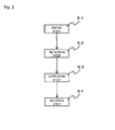
- Fig. 2 is a flowchart that illustrates the process for producing the blow-molded foam according to the present invention.
- the process for producing a blow-molded foam according to this embodiment includes a mixing step S1 of adding a thermoplastic resin to a foaming agent and mixing the thermoplastic resin with the foaming agent in an extruder to prepare a resin mixture, a retaining step S2 of retaining the resin mixture at a cylinder-shaped space defined between a mandrel and a die outer cylinder, an extruding step S3 of extruding a parison from a die slit by use of a ring-shaped piston, and a molding step S4 of subjecting the parison to blow molding by clamping split mold blocks with the parison inserted therebetween and blowing air on the parison.
- the process for producing a blow-molded foam since the parison is extruded at a predetermined extrusion rate by using the ring-shaped piston, the blow molding is carried out, with the size of the foamed cells being maintained.
- the process for producing the blow-molded foam makes it possible to obtain a blow-molded foam which has homogeneous foamed cells in size, is light in weight, and is excellent in surface smoothness.
- the mixing step S1 is a step of adding a thermoplastic resin to a foaming agent and mixing the thermoplastic resin with the foaming agent in the extruder to prepare a resin mixture.
- any one of conventionally known machines may be used on demand as the extruder.
- the polyolefin-based resin described above is used as the thermoplastic resin, and the foaming agent is used in its supercritical state. By using the foaming agent that is a supercritical fluid, the foamed cells are made finer.
- the foaming agent is preferably prepared as a carbon dioxide gas or a nitrogen gas.
- These gases can be made into a supercritical state under comparatively moderate conditions. More specifically, in the case where the carbon dioxide gas is used as the supercritical fluid, the following conditions are set: the critical temperature is 31 °C and the critical pressure is not less than 7.4 MPa. In the case where the nitrogen gas is used as the supercritical fluid, the following conditions are set: the critical temperature is 149.1 °C and the critical pressure is not less than 3.4 MPa.
- a resin mixture is obtained.
- a styrene-based elastomer and/or a low-density polyethylene may be added to the polyolefin.
- the retaining step S2 is a step of retaining the resin mixture at a cylinder-shaped space defined between a mandrel and a die outer cylinder.
- the retaining step is carried out using an extrusion head.
- Fig. 3 is a partial section view that illustrates the extrusion head for use in the process for producing a blow-molded foam according to the present invention.
- the extrusion head 20 includes a die outer cylinder 28, a mandrel 27 that is placed substantially in the center of the die outer cylinder 28, a cylinder-shaped space 29 defined between the die outer cylinder 28 and the mandrel 27, a ring-shaped piston 22 for pressing the resin mixture retained at the cylinder-shaped space 29 downward, and a die slit 21 for discharging the resin.
- the resin mixture extruded by an extruder moves along the periphery of the mandrel 27, is dropped in the cylinder-shaped space 29 between the mandrel 27 and the die outer cylinder 28, and is retained at the cylinder-shaped space 29.
- the amount of resin to be retained is preferably 5 to 40 liters.
- the extruding step S3 is a step of extruding a parison from a die slit by use of a ring-shaped piston. That is, after a predetermined amount of the resin has been retained at the cylinder-shaped space 29, the parison (not illustrated) is discharged through the die slit 21 by pressing the ring-shaped piston 22 downward.
- a system in which the ring-shaped piston 22 extrudes the parison in the die (an accumulator-inside-die system or an accumulator head system) is adopted, it is possible to shorten the distance of the die slit 21, and also to increase the extrusion rate. Thus, it becomes possible to maintain the state of the foamed cells.
- a conventional extrusion head illustrated in Fig. 9 has a system in which the parison is extruded using an accumulator 35 placed outside the die (an accumulator-outside-die system) is adopted, the distance of the die slit is made longer, failing to increase the extrusion rate.
- the extrusion rate of the parison is preferably not less than 700 kg/hr. In this case, it is possible to obtain a blow-molded foam having excellent surface smoothness.
- the accumulator inside the die which is used in the present invention, has an injection rate of not less than 200 cm 3 /sec, preferably, not less than 500 cm 3 /sec.
- the molding step S4 is a step of subjecting the parison to blow molding by clamping split mold blocks with the parison inserted therebetween and blowing air on the parison.
- Fig. 4 is a section view that illustrates a method of blow molding in the process for producing a blow-molded foam according to the present invention.
- the cylinder-shaped parison 32 is extruded between the split mold blocks 33 from the die slit (not illustrated). Then, the split mold blocks 33 are clamped with the parison 32 inserted therebetween.
- the pressure used for blowing air is preferably 0.05 to 0.15 MPa, from the viewpoint of maintaining the shape of foamed cell.
- a blow-molded foam is obtained.
- the foamed cells can be homogenized in size, and by extruding the resin mixture at a predetermined extrusion rate by using a ring-shaped piston, blow molding is carried out with the size of the foamed cell appropriately maintained.
- blow molding is carried out with the size of the foamed cell appropriately maintained.
- Fig. 5 is a perspective view that illustrates a blow-molded foam according to a second embodiment of the present invention.
- a blow-molded foam (hereinafter, referred to also as "skinned panel") 3 has a hollow structure with double walls, including wall portions that are formed in such a manner that a thermoplastic resin containing a foaming agent mixed therewith is subjected to blow molding.
- a skin material 4 is bonded to one of surfaces of a base body 2 made of the wall portion. Such a skin material 4 is integrally bonded to the base body 2, simultaneously with the blow molding of the wall portion in the molding step.
- Fig. 6 is a section view of the blow-molded foam illustrated in Fig. 5 .
- the base body 2 made of the wall portion has a hollow structure with double walls, with a hollow portion 5 included therein, and a plurality of reinforcing ribs 6 are formed so as to divide the hollow portion 5.
- the reinforcing ribs 6 make it possible to improve the strength in a vertical direction.
- the reinforcing ribs 6 are formed by pressing the parison wall portion onto the parison side face in a manner so as to be folded down, by a slide core having a protruding shape in one direction. Therefore, in the production of the skinned panel, in the molding step, the reinforcing ribs 6 are also formed simultaneously with the bonding of the skin material 4.
- the wall portion is synonymous with the "wall portion" in the blow-molded foam according to the first embodiment, and since the structures and physical properties thereof are also the same, the description thereof will be omitted.
- the process for producing the blow-molded foam according to the second embodiment is the same as the process for producing the blow-molded foam according to the first embodiment, except for the foregoing difference in the molding step.
- the wall portion has a closed cell structure in which a plurality of foamed cells are formed.
- the expansion ratio of the wall portion is set in a predetermined range, it is possible to provide a lightweight structure.
- the standard deviation of the cell diameter of the foamed cell in the thickness direction of the wall portion is set in a predetermined range, it is possible to provide the homogeneous foamed cells in size.
- the center-line average surface roughness Ra on the outer face of the wall portion is set in a predetermined range, it is possible to achieve high surface smoothness.
- a propylene homopolymer (thermoplastic resin: trade name: PF814, made by SunAllomer) (70 wt%) having an MFR of 3.0 g/min at 230°C, with a long-chain branched structure introduced therein, and a crystalline ethylene-propylene block copolymer (NOVATECH PP EC9, made by Japan Polychem) (30 wt%) having an MFR of 0.5 g/min at 230°C were mixed to form a mixture, and 96 parts by weight of this mixture, 3 parts by weight of talc MB (master batch) serving as a core agent and 1 part by weight of black MB (master batch) serving as a colorant were mixed.
- thermoplastic resin trade name: PF814, made by SunAllomer
- NOVATECH PP EC9 crystalline ethylene-propylene block copolymer
- the density of the resin mixture was 0.91 g/cm 3 .
- carbon dioxide gas in a supercritical state as a foaming agent to be foamed so that a resin mixture was prepared.
- the resin mixture was retained at a cylinder-shaped space defined between a mandrel and a die outer cylinder by using an extrusion head illustrated in Fig. 3 , and a cylinder-shaped parison was extruded between split mold blocks illustrated in Fig.
- the MFR was measured in conformity with JIS K-7210, with a test load of 2.16 kg being applied thereto.
- Example 2 The same processes as those of Example 1 were carried out except that the extrusion rate was changed to 750 kg/hr so that a sample B was obtained.
- Example 2 The same processes as those of Example 1 were carried out except that in place of the carbon dioxide gas, nitrogen gas was used so that a sample C was obtained.
- Example 2 The same processes as those of Example 1 were carried out except that in place of the carbon dioxide gas, nitrogen gas was used, and that the extrusion rate was changed to 700 kg/hr so that a sample D was obtained.
- Example 2 The same processes as those of Example 1 were carried out except that in place of the carbon dioxide gas, nitrogen gas was used, and that the extrusion rate was changed to 600 kg/hr so that a sample E was obtained.
- Example 2 The same processes as those of Example 1 were carried out except that the extrusion rate was changed to 600 kg/hr so that a sample F was obtained.
- a conventional extrusion head illustrated in Fig. 9 was used. That is, the resin mixture that had been mixed in an extruder was supplied to a cross head by using a plunger, from an accumulator cylinder (accumulator outside die) in the horizontal direction, installed outside the die head, and extruded as a cylinder-shaped parison through a die slit. Moreover, the extrusion rate was set to 450 kg/hr. Except for the above-mentioned points, the same processes as those of Example 1 were carried out so that a sample G was obtained.
- the expansion ratio was calculated by dividing the density of each of resin mixtures used in the samples A to I by the apparent density of the corresponding wall faces of the samples A to I.
- the center-line average surface roughness of each of the samples A to I was measured by using a surface-roughness measuring device (SURFCOM 470A, made by Tokyo Seimitsu Co., Ltd.).
- SURFCOM 470A surface-roughness measuring device
- 5 points on the outside of the wall face and 5 points on the inside of the wall face of the blow-molded foam were measured, and an average value was obtained.
- Fig. 7 illustrates a photograph of the sample A of Example 1, thus obtained
- Fig. 8 illustrates a photograph of the sample G of Comparative Example 1, thus obtained.
- a non-woven fabric (hereinafter, referred to as "packing") (thickness: 3 mm, width: 10 mm) to which double-sided tapes had been bonded, and one of the end faces of the packing was adhered and secured to the test piece, with the other end face being attached to a tensile testing machine.
- the other end face of the packing was pulled by the tensile testing machine in a manner so as to be folded over to the other end face side, and the peel strength at this time was measured.
- a non-woven fabric/acryl-based adhesive material (interior member securing double-sided tape #5782, made by Sekisui Chemical Co., Ltd.) having an adhesive strength of 18.6 N/25 mm measured in conformity with JIS Z0237 (180° peeling method) was used, and the tension rate was set to 300 mm/min.
- Table 2 shows the results of the tests.
- the peel strength was excellent in comparison with those of the samples G to I of Comparative Examples 1 to 3.
- the blow-molded foam of the present invention was confirmed to be excellent in smoothness.
- the present invention could provide a blow-molded foam which has homogeneous foamed cells in size, is light in weight and is excellent in surface smoothness.
- the blow-molded foam of the present invention is applicable to an interior material for vehicles, and the like.
- the blow-molded foam makes it possible to devote to weight reduction of a vehicle without causing degradation of various physical properties as plastic parts.
Landscapes
- Engineering & Computer Science (AREA)
- Mechanical Engineering (AREA)
- Manufacturing & Machinery (AREA)
- Physics & Mathematics (AREA)
- Thermal Sciences (AREA)
- Blow-Moulding Or Thermoforming Of Plastics Or The Like (AREA)
- Molding Of Porous Articles (AREA)
Priority Applications (2)
| Application Number | Priority Date | Filing Date | Title |
|---|---|---|---|
| EP14188328.0A EP2842720B8 (de) | 2008-03-31 | 2009-03-31 | Verfahren zur herstellung von blasgeformter schaumstoff |
| EP21172209.5A EP3878625B1 (de) | 2008-03-31 | 2009-03-31 | Blasgeformter schaumsotff und verfahren zur herstellung von blasgeformter schaumsotff |
Applications Claiming Priority (2)
| Application Number | Priority Date | Filing Date | Title |
|---|---|---|---|
| JP2008093894A JP5025549B2 (ja) | 2008-03-31 | 2008-03-31 | 発泡ブロー成形品およびその製造方法 |
| PCT/JP2009/001519 WO2009122735A1 (ja) | 2008-03-31 | 2009-03-31 | 発泡ブロー成形体及びその製造方法 |
Related Child Applications (3)
| Application Number | Title | Priority Date | Filing Date |
|---|---|---|---|
| EP21172209.5A Division EP3878625B1 (de) | 2008-03-31 | 2009-03-31 | Blasgeformter schaumsotff und verfahren zur herstellung von blasgeformter schaumsotff |
| EP14188328.0A Division EP2842720B8 (de) | 2008-03-31 | 2009-03-31 | Verfahren zur herstellung von blasgeformter schaumstoff |
| EP14188328.0A Division-Into EP2842720B8 (de) | 2008-03-31 | 2009-03-31 | Verfahren zur herstellung von blasgeformter schaumstoff |
Publications (3)
| Publication Number | Publication Date |
|---|---|
| EP2261004A1 true EP2261004A1 (de) | 2010-12-15 |
| EP2261004A4 EP2261004A4 (de) | 2013-01-09 |
| EP2261004B1 EP2261004B1 (de) | 2014-12-17 |
Family
ID=41135135
Family Applications (3)
| Application Number | Title | Priority Date | Filing Date |
|---|---|---|---|
| EP09728880.7A Active EP2261004B1 (de) | 2008-03-31 | 2009-03-31 | Rohr für Temperaturregelungssysteme und Verfahren zur Herstellung |
| EP14188328.0A Active EP2842720B8 (de) | 2008-03-31 | 2009-03-31 | Verfahren zur herstellung von blasgeformter schaumstoff |
| EP21172209.5A Active EP3878625B1 (de) | 2008-03-31 | 2009-03-31 | Blasgeformter schaumsotff und verfahren zur herstellung von blasgeformter schaumsotff |
Family Applications After (2)
| Application Number | Title | Priority Date | Filing Date |
|---|---|---|---|
| EP14188328.0A Active EP2842720B8 (de) | 2008-03-31 | 2009-03-31 | Verfahren zur herstellung von blasgeformter schaumstoff |
| EP21172209.5A Active EP3878625B1 (de) | 2008-03-31 | 2009-03-31 | Blasgeformter schaumsotff und verfahren zur herstellung von blasgeformter schaumsotff |
Country Status (6)
| Country | Link |
|---|---|
| US (6) | US8517059B2 (de) |
| EP (3) | EP2261004B1 (de) |
| JP (1) | JP5025549B2 (de) |
| CN (2) | CN102046355B (de) |
| ES (1) | ES2527956T3 (de) |
| WO (1) | WO2009122735A1 (de) |
Cited By (1)
| Publication number | Priority date | Publication date | Assignee | Title |
|---|---|---|---|---|
| EP2783830A4 (de) * | 2012-01-26 | 2015-08-26 | Kyoraku Co Ltd | Verfahren zur herstellung eines geformten schaumstoffgegenstandes und geformter schaumstoffgegenstand |
Families Citing this family (32)
| Publication number | Priority date | Publication date | Assignee | Title |
|---|---|---|---|---|
| JP5053907B2 (ja) * | 2008-03-31 | 2012-10-24 | キョーラク株式会社 | 軽量空調ダクト |
| JP5025549B2 (ja) * | 2008-03-31 | 2012-09-12 | キョーラク株式会社 | 発泡ブロー成形品およびその製造方法 |
| JP5589651B2 (ja) * | 2010-07-30 | 2014-09-17 | キョーラク株式会社 | 発泡成形体の製造方法、及び発泡成形体 |
| JP5796285B2 (ja) * | 2010-09-14 | 2015-10-21 | キョーラク株式会社 | ダクトの成形方法 |
| US9079352B2 (en) * | 2010-09-14 | 2015-07-14 | Kyoraku Co., Ltd. | Duct molding method and duct |
| US9102093B2 (en) | 2010-09-14 | 2015-08-11 | Kyoraku Co., Ltd. | Molding apparatus and molding method |
| JP5867077B2 (ja) * | 2011-01-31 | 2016-02-24 | キョーラク株式会社 | 樹脂成形品の成形方法 |
| JP5367884B2 (ja) * | 2011-08-31 | 2013-12-11 | キョーラク株式会社 | 板状部分付き管状発泡成形体及びその成形方法 |
| CN103171123B (zh) * | 2011-12-20 | 2017-04-12 | 京洛株式会社 | 中空发泡成形体的制造方法及中空发泡成形体 |
| US9266259B2 (en) | 2011-12-23 | 2016-02-23 | Kyoraku Co. Ltd. | Method of forming hollow blow-molded foam and such hollow blow-molded foam |
| JP2013178034A (ja) * | 2012-02-28 | 2013-09-09 | Kyoraku Co Ltd | 発泡ダクト |
| JP5982870B2 (ja) * | 2012-02-28 | 2016-08-31 | キョーラク株式会社 | 発泡ダクト |
| WO2014066438A1 (en) * | 2012-10-22 | 2014-05-01 | Mars, Incorporated | Aerated injection molded pet chew |
| JP6541938B2 (ja) * | 2013-05-14 | 2019-07-10 | 株式会社ジェイエスピー | ダクト |
| RU2610497C1 (ru) * | 2013-12-03 | 2017-02-13 | Ниссан Мотор Ко., Лтд. | Отформованный из вспененного материала корпус, трубопровод для кондиционера воздуха и трубопровод для кондиционера воздуха транспортного средства |
| JP6331390B2 (ja) * | 2013-12-27 | 2018-05-30 | キョーラク株式会社 | 発泡成形体 |
| JP6418767B2 (ja) * | 2014-04-02 | 2018-11-07 | ユニチカ株式会社 | 発泡ブロー成形用ポリアミド樹脂組成物およびそれより得られる成形体 |
| JP6344056B2 (ja) * | 2014-05-23 | 2018-06-20 | キョーラク株式会社 | 発泡成形体 |
| KR101637273B1 (ko) | 2014-06-13 | 2016-07-07 | 현대자동차 주식회사 | 폴리올레핀 수지 성형품, 그 제조방법 및 이를 이용한 에어덕트 |
| US20150362097A1 (en) * | 2014-06-17 | 2015-12-17 | Unique Fabricating, Inc. | Foam duct with captured insert for improved connectability |
| US11161285B2 (en) | 2014-08-20 | 2021-11-02 | Toledo Molding & Die, Inc. | Sub-ambient pressure morphology control process for use in molding extruded polymer foams, and parts produced therefrom |
| CN107073791B (zh) | 2014-08-20 | 2019-11-08 | 托莱多制模和冲模股份有限公司 | 用于模制挤出聚合物泡沫的低于常压形态控制工艺及由此产生的制件 |
| JP6920604B2 (ja) * | 2016-10-31 | 2021-08-18 | キョーラク株式会社 | 発泡成形体、及びその製造方法 |
| US10988584B2 (en) | 2016-10-31 | 2021-04-27 | Kyoraku Co., Ltd. | Resin for foam molding, foam molded article, and method for producing same |
| JP6845426B2 (ja) * | 2017-02-27 | 2021-03-17 | キョーラク株式会社 | 発泡成形用樹脂、発泡成形体及びその製造方法 |
| JP6920610B2 (ja) * | 2017-04-27 | 2021-08-18 | キョーラク株式会社 | 発泡ダクト |
| US12031644B2 (en) * | 2018-07-26 | 2024-07-09 | Kyoraku Co., Ltd. | Tubular formed body, and storage structure |
| FR3090509B1 (fr) * | 2018-12-19 | 2022-04-29 | Valeo Systemes Thermiques | Boîtier pour module de face avant d’un véhicule automobile |
| CN109834920A (zh) * | 2018-12-26 | 2019-06-04 | 天津富松汽车零部件有限公司 | 中空吹塑内部发泡成型体的吹塑设备 |
| JP7029685B2 (ja) * | 2019-03-26 | 2022-03-04 | 東レ株式会社 | ポリオレフィン系樹脂発泡シート |
| WO2022038199A1 (en) | 2020-08-18 | 2022-02-24 | Rieke Packaging Systems Limited | All-polymer helical biasing member and pump dispenser incorporating same |
| CN112339249B (zh) * | 2020-10-09 | 2021-08-24 | 长沙水星包装有限公司 | 综合性水桶挤吹成型设备 |
Family Cites Families (37)
| Publication number | Priority date | Publication date | Assignee | Title |
|---|---|---|---|---|
| JPS5624289A (en) * | 1979-07-31 | 1981-03-07 | Furukawa Electric Co Ltd | Adiabatic pipe and its manufacture |
| DE3272913D1 (en) | 1981-10-22 | 1986-10-02 | Ici Plc | Production of pvc irrigation pipe |
| DE3708006A1 (de) * | 1987-03-12 | 1988-09-22 | Kautex Maschinenbau Gmbh | Verfahren zum herstellen von hohlkoerpern aus thermoplastischem kunststoff mit einer mehrschichtigen wandung |
| JPH0825230B2 (ja) | 1987-06-12 | 1996-03-13 | エクセル株式会社 | 内周面上の発泡セルを破裂させた中空成形品及びその製造方法 |
| US4931327A (en) * | 1989-06-14 | 1990-06-05 | Mobil Oil Corporation | White opaque opp film for tamper evident package |
| US5453310A (en) * | 1992-08-11 | 1995-09-26 | E. Khashoggi Industries | Cementitious materials for use in packaging containers and their methods of manufacture |
| IL108671A (en) * | 1993-02-17 | 1998-08-16 | Khashoggi E Ind | Organically bound inorganically filled articles and methods and systems for forming such articles |
| EP0747781B1 (de) * | 1995-06-07 | 2001-10-24 | Canon Kabushiki Kaisha | Drehteil aus geschäumtem Material mit Orientierung der Drehachse längs zur Zellhauptachse, und Entwicklungsvorrichtung unter Verwendung derselben als Tonerzuführeinheit |
| BR9610557A (pt) * | 1995-09-20 | 1999-12-21 | Uponor Bv | Produtos poliméricos orientados |
| US5830393A (en) * | 1996-07-10 | 1998-11-03 | Mitsui Chemicals, Inc. | Process for preparing expanded product of thermoplastic resin |
| JP3745960B2 (ja) | 1997-11-28 | 2006-02-15 | 株式会社ジェイエスピー | 発泡ブロー成形品及びその製造方法 |
| ATE290041T1 (de) * | 1997-12-19 | 2005-03-15 | Trexel Inc | Mikrozellulares schaumstoff- extrusions/blasformverfahren und damit hergestellter gegenstand |
| US6706223B1 (en) * | 1997-12-19 | 2004-03-16 | Trexel, Inc. | Microcelluar extrusion/blow molding process and article made thereby |
| JP3646858B2 (ja) * | 1999-08-09 | 2005-05-11 | 株式会社ジェイエスピー | 多層ポリプロピレン系樹脂発泡成形体及びその製造方法、並びに容器 |
| KR20020013784A (ko) * | 2000-08-10 | 2002-02-21 | 요시우라 하루끼 | 개질폴리프로필렌, 개질폴리프로필렌의 제조방법,개질폴리프로필렌조성물 및 발포체 |
| JP4955853B2 (ja) * | 2000-12-25 | 2012-06-20 | 株式会社ジェイエスピー | オレフィン系樹脂発泡層を有する発泡成形体の製造方法 |
| US7074027B2 (en) * | 2001-02-19 | 2006-07-11 | Starita Joseph M | Extrusion die and method for forming dual wall corrugated plastic pipe and dual wall plastic pipe having a foam annular core |
| US6749794B2 (en) * | 2001-08-13 | 2004-06-15 | R + S Technik Gmbh | Method and apparatus for molding components with molded-in surface texture |
| US20030051764A1 (en) * | 2001-09-20 | 2003-03-20 | Jungers Jon W. | Air handling system ductwork component and method of manufacture |
| JP3707779B2 (ja) * | 2002-02-15 | 2005-10-19 | 株式会社ジェイエスピー | 発泡成形体の製造方法及び発泡成形体 |
| JP3997334B2 (ja) * | 2002-09-27 | 2007-10-24 | 株式会社ジェイエスピー | ブロー成形体からなるダクト |
| JP4084209B2 (ja) * | 2003-02-21 | 2008-04-30 | 株式会社ジェイエスピー | 発泡成形体及びその製造方法 |
| JP4033048B2 (ja) * | 2003-06-11 | 2008-01-16 | ソニー株式会社 | スピーカ振動板の製造方法及びスピーカ振動板 |
| WO2005035286A1 (de) * | 2003-10-08 | 2005-04-21 | Behr Gmbh & Co. Kg | Bauteil, insbesondere hybridträger für ein fahrzeug, und verfahren zur herstellung eines derartigen bauteils sowie verwendung eines derartigen bauteils |
| JP4822670B2 (ja) | 2004-02-27 | 2011-11-24 | キョーラク株式会社 | 発泡体ダクト |
| JP4814519B2 (ja) * | 2004-12-28 | 2011-11-16 | キョーラク株式会社 | ポリプロピレン系樹脂発泡成形体 |
| EP1902960B1 (de) * | 2005-07-13 | 2016-02-17 | Toyo Seikan Kaisha, Ltd. | Herstellungsverfahren für einen perlenförmigen kunststoffbehälter |
| BRPI0706060A2 (pt) * | 2007-02-05 | 2011-03-22 | American Fuji Seal Inc | folha com espuma contraìvel por aquecimento e recipiente |
| US9669593B2 (en) * | 2007-06-14 | 2017-06-06 | The Boeing Company | Light weight thermoplastic flex foam and hybrid duct system |
| WO2009119549A1 (ja) * | 2008-03-27 | 2009-10-01 | 東洋製罐株式会社 | 延伸発泡プラスチック容器及びその製造方法 |
| JP5025549B2 (ja) * | 2008-03-31 | 2012-09-12 | キョーラク株式会社 | 発泡ブロー成形品およびその製造方法 |
| JP5609423B2 (ja) * | 2009-09-30 | 2014-10-22 | キョーラク株式会社 | 空調ダクトの製造方法、及び空調ダクト |
| JP5803086B2 (ja) * | 2009-10-31 | 2015-11-04 | キョーラク株式会社 | 発泡成形体の成形方法及び発泡成形体 |
| US9266259B2 (en) * | 2011-12-23 | 2016-02-23 | Kyoraku Co. Ltd. | Method of forming hollow blow-molded foam and such hollow blow-molded foam |
| CA2861849C (en) * | 2012-02-07 | 2016-11-22 | Toyo Seikan Group Holdings, Ltd. | Vapor-deposited foamed body |
| KR101639743B1 (ko) * | 2012-03-26 | 2016-07-14 | 도요세이칸 그룹 홀딩스 가부시키가이샤 | 금속색의 외관을 갖는 연신 발포 플라스틱 성형체 |
| US10434691B2 (en) * | 2012-10-10 | 2019-10-08 | Kyoraku Co., Ltd. | Foam molded article and molding method for same |
-
2008
- 2008-03-31 JP JP2008093894A patent/JP5025549B2/ja active Active
-
2009
- 2009-03-31 EP EP09728880.7A patent/EP2261004B1/de active Active
- 2009-03-31 EP EP14188328.0A patent/EP2842720B8/de active Active
- 2009-03-31 CN CN200980119253.8A patent/CN102046355B/zh active Active
- 2009-03-31 CN CN201410244460.9A patent/CN104015340B/zh active Active
- 2009-03-31 ES ES09728880.7T patent/ES2527956T3/es active Active
- 2009-03-31 EP EP21172209.5A patent/EP3878625B1/de active Active
- 2009-03-31 US US12/935,520 patent/US8517059B2/en active Active
- 2009-03-31 WO PCT/JP2009/001519 patent/WO2009122735A1/ja not_active Ceased
-
2013
- 2013-07-24 US US13/950,248 patent/US9340091B2/en active Active
- 2013-07-24 US US13/949,266 patent/US9186955B2/en active Active
-
2016
- 2016-05-16 US US15/156,297 patent/US10369727B2/en active Active
-
2019
- 2019-06-28 US US16/457,846 patent/US11045982B2/en active Active
-
2021
- 2021-05-21 US US17/326,645 patent/US11833723B2/en active Active
Cited By (2)
| Publication number | Priority date | Publication date | Assignee | Title |
|---|---|---|---|---|
| EP2783830A4 (de) * | 2012-01-26 | 2015-08-26 | Kyoraku Co Ltd | Verfahren zur herstellung eines geformten schaumstoffgegenstandes und geformter schaumstoffgegenstand |
| US9527228B2 (en) | 2012-01-26 | 2016-12-27 | Kyoraku Co., Ltd. | Method for producing foam-molded article, and foam-molded article |
Also Published As
| Publication number | Publication date |
|---|---|
| EP2842720A1 (de) | 2015-03-04 |
| WO2009122735A1 (ja) | 2009-10-08 |
| EP3878625B1 (de) | 2026-03-18 |
| CN104015340B (zh) | 2019-03-08 |
| US20190322009A1 (en) | 2019-10-24 |
| US11045982B2 (en) | 2021-06-29 |
| CN102046355B (zh) | 2014-08-27 |
| US20210276232A1 (en) | 2021-09-09 |
| US20130313749A1 (en) | 2013-11-28 |
| ES2527956T3 (es) | 2015-02-02 |
| US9340091B2 (en) | 2016-05-17 |
| JP2009241528A (ja) | 2009-10-22 |
| EP2842720B8 (de) | 2021-09-01 |
| EP2261004B1 (de) | 2014-12-17 |
| EP2842720B1 (de) | 2021-06-16 |
| US20130323448A1 (en) | 2013-12-05 |
| US9186955B2 (en) | 2015-11-17 |
| US20110048571A1 (en) | 2011-03-03 |
| CN102046355A (zh) | 2011-05-04 |
| US8517059B2 (en) | 2013-08-27 |
| EP3878625A1 (de) | 2021-09-15 |
| US20160257040A1 (en) | 2016-09-08 |
| US11833723B2 (en) | 2023-12-05 |
| US10369727B2 (en) | 2019-08-06 |
| CN104015340A (zh) | 2014-09-03 |
| EP2261004A4 (de) | 2013-01-09 |
| JP5025549B2 (ja) | 2012-09-12 |
Similar Documents
| Publication | Publication Date | Title |
|---|---|---|
| US11833723B2 (en) | Blow-molded foam and process for producing the same | |
| US8448671B2 (en) | Light-weight air conditioning duct for vehicle | |
| EP2551088A1 (de) | Verfahren zur herstellung eines blasgeformten artikels aus einem harzschaumstoff auf polypropylenbasis | |
| EP2783830B1 (de) | Verfahren zur herstellung eines geformten schaumstoffgegenstandes und geformter schaumstoffgegenstand | |
| JP5301238B2 (ja) | 熱可塑性樹脂発泡体の製造方法 | |
| EP2628990A1 (de) | Formschaum | |
| JP5422246B2 (ja) | 発泡ブロー成形体及びその製造方法 | |
| WO2013073461A1 (ja) | 発泡成形品およびその製造方法 | |
| JPWO2013114996A1 (ja) | 発泡成形品の製造方法および発泡成形品 | |
| EP3533823B1 (de) | Harz zum schaumformen, schaumgeformter artikel und herstellungsverfahren dafür | |
| JP5428061B2 (ja) | 発泡ブロー成形品 | |
| EP4082749B1 (de) | Expansionsformtkörper und verfahren zum produzieren eines formkörpers | |
| JP6174462B2 (ja) | 発泡ブロー成形品 |
Legal Events
| Date | Code | Title | Description |
|---|---|---|---|
| PUAI | Public reference made under article 153(3) epc to a published international application that has entered the european phase |
Free format text: ORIGINAL CODE: 0009012 |
|
| 17P | Request for examination filed |
Effective date: 20100930 |
|
| AK | Designated contracting states |
Kind code of ref document: A1 Designated state(s): AT BE BG CH CY CZ DE DK EE ES FI FR GB GR HR HU IE IS IT LI LT LU LV MC MK MT NL NO PL PT RO SE SI SK TR |
|
| AX | Request for extension of the european patent |
Extension state: AL BA RS |
|
| DAX | Request for extension of the european patent (deleted) | ||
| A4 | Supplementary search report drawn up and despatched |
Effective date: 20121210 |
|
| RIC1 | Information provided on ipc code assigned before grant |
Ipc: B29K 23/00 20060101ALI20121204BHEP Ipc: B29K 105/04 20060101ALI20121204BHEP Ipc: B29C 49/04 20060101AFI20121204BHEP |
|
| 17Q | First examination report despatched |
Effective date: 20130521 |
|
| GRAP | Despatch of communication of intention to grant a patent |
Free format text: ORIGINAL CODE: EPIDOSNIGR1 |
|
| RIC1 | Information provided on ipc code assigned before grant |
Ipc: B29L 23/00 20060101ALI20140606BHEP Ipc: B60H 1/00 20060101ALI20140606BHEP Ipc: B29K 105/04 20060101ALI20140606BHEP Ipc: B29C 49/04 20060101AFI20140606BHEP Ipc: B29K 23/00 20060101ALI20140606BHEP Ipc: B29C 49/00 20060101ALI20140606BHEP Ipc: B29L 31/30 20060101ALI20140606BHEP Ipc: B29C 44/34 20060101ALI20140606BHEP Ipc: B29C 49/48 20060101ALI20140606BHEP |
|
| INTG | Intention to grant announced |
Effective date: 20140626 |
|
| RIN1 | Information on inventor provided before grant (corrected) |
Inventor name: TAMADA, TERUO Inventor name: SUMI, TAKEHIKO Inventor name: IGARASHI, YU Inventor name: ONODERA, MASAAKI Inventor name: OHNO, YOSHINORI |
|
| GRAS | Grant fee paid |
Free format text: ORIGINAL CODE: EPIDOSNIGR3 |
|
| GRAA | (expected) grant |
Free format text: ORIGINAL CODE: 0009210 |
|
| AK | Designated contracting states |
Kind code of ref document: B1 Designated state(s): AT BE BG CH CY CZ DE DK EE ES FI FR GB GR HR HU IE IS IT LI LT LU LV MC MK MT NL NO PL PT RO SE SI SK TR |
|
| REG | Reference to a national code |
Ref country code: GB Ref legal event code: FG4D |
|
| REG | Reference to a national code |
Ref country code: CH Ref legal event code: EP |
|
| REG | Reference to a national code |
Ref country code: IE Ref legal event code: FG4D |
|
| REG | Reference to a national code |
Ref country code: AT Ref legal event code: REF Ref document number: 701553 Country of ref document: AT Kind code of ref document: T Effective date: 20150115 |
|
| REG | Reference to a national code |
Ref country code: ES Ref legal event code: FG2A Ref document number: 2527956 Country of ref document: ES Kind code of ref document: T3 Effective date: 20150202 |
|
| REG | Reference to a national code |
Ref country code: DE Ref legal event code: R096 Ref document number: 602009028373 Country of ref document: DE Effective date: 20150219 |
|
| RAP2 | Party data changed (patent owner data changed or rights of a patent transferred) |
Owner name: KYORAKU CO., LTD. |
|
| RIN2 | Information on inventor provided after grant (corrected) |
Inventor name: TAMADA, TERUO Inventor name: IGARASHI, YU Inventor name: SUMI, TAKEHIKO Inventor name: OHNO, YOSHINORI Inventor name: ONODERA, MASAAKI |
|
| REG | Reference to a national code |
Ref country code: DE Ref legal event code: R083 Ref document number: 602009028373 Country of ref document: DE |
|
| PG25 | Lapsed in a contracting state [announced via postgrant information from national office to epo] |
Ref country code: NO Free format text: LAPSE BECAUSE OF FAILURE TO SUBMIT A TRANSLATION OF THE DESCRIPTION OR TO PAY THE FEE WITHIN THE PRESCRIBED TIME-LIMIT Effective date: 20150317 Ref country code: LT Free format text: LAPSE BECAUSE OF FAILURE TO SUBMIT A TRANSLATION OF THE DESCRIPTION OR TO PAY THE FEE WITHIN THE PRESCRIBED TIME-LIMIT Effective date: 20141217 Ref country code: FI Free format text: LAPSE BECAUSE OF FAILURE TO SUBMIT A TRANSLATION OF THE DESCRIPTION OR TO PAY THE FEE WITHIN THE PRESCRIBED TIME-LIMIT Effective date: 20141217 |
|
| REG | Reference to a national code |
Ref country code: LT Ref legal event code: MG4D |
|
| PG25 | Lapsed in a contracting state [announced via postgrant information from national office to epo] |
Ref country code: HR Free format text: LAPSE BECAUSE OF FAILURE TO SUBMIT A TRANSLATION OF THE DESCRIPTION OR TO PAY THE FEE WITHIN THE PRESCRIBED TIME-LIMIT Effective date: 20141217 Ref country code: SE Free format text: LAPSE BECAUSE OF FAILURE TO SUBMIT A TRANSLATION OF THE DESCRIPTION OR TO PAY THE FEE WITHIN THE PRESCRIBED TIME-LIMIT Effective date: 20141217 Ref country code: GR Free format text: LAPSE BECAUSE OF FAILURE TO SUBMIT A TRANSLATION OF THE DESCRIPTION OR TO PAY THE FEE WITHIN THE PRESCRIBED TIME-LIMIT Effective date: 20150318 Ref country code: LV Free format text: LAPSE BECAUSE OF FAILURE TO SUBMIT A TRANSLATION OF THE DESCRIPTION OR TO PAY THE FEE WITHIN THE PRESCRIBED TIME-LIMIT Effective date: 20141217 |
|
| REG | Reference to a national code |
Ref country code: AT Ref legal event code: MK05 Ref document number: 701553 Country of ref document: AT Kind code of ref document: T Effective date: 20141217 |
|
| PG25 | Lapsed in a contracting state [announced via postgrant information from national office to epo] |
Ref country code: NL Free format text: LAPSE BECAUSE OF FAILURE TO SUBMIT A TRANSLATION OF THE DESCRIPTION OR TO PAY THE FEE WITHIN THE PRESCRIBED TIME-LIMIT Effective date: 20141217 |
|
| PG25 | Lapsed in a contracting state [announced via postgrant information from national office to epo] |
Ref country code: CZ Free format text: LAPSE BECAUSE OF FAILURE TO SUBMIT A TRANSLATION OF THE DESCRIPTION OR TO PAY THE FEE WITHIN THE PRESCRIBED TIME-LIMIT Effective date: 20141217 Ref country code: EE Free format text: LAPSE BECAUSE OF FAILURE TO SUBMIT A TRANSLATION OF THE DESCRIPTION OR TO PAY THE FEE WITHIN THE PRESCRIBED TIME-LIMIT Effective date: 20141217 Ref country code: SK Free format text: LAPSE BECAUSE OF FAILURE TO SUBMIT A TRANSLATION OF THE DESCRIPTION OR TO PAY THE FEE WITHIN THE PRESCRIBED TIME-LIMIT Effective date: 20141217 Ref country code: RO Free format text: LAPSE BECAUSE OF FAILURE TO SUBMIT A TRANSLATION OF THE DESCRIPTION OR TO PAY THE FEE WITHIN THE PRESCRIBED TIME-LIMIT Effective date: 20141217 |
|
| PG25 | Lapsed in a contracting state [announced via postgrant information from national office to epo] |
Ref country code: PL Free format text: LAPSE BECAUSE OF FAILURE TO SUBMIT A TRANSLATION OF THE DESCRIPTION OR TO PAY THE FEE WITHIN THE PRESCRIBED TIME-LIMIT Effective date: 20141217 Ref country code: AT Free format text: LAPSE BECAUSE OF FAILURE TO SUBMIT A TRANSLATION OF THE DESCRIPTION OR TO PAY THE FEE WITHIN THE PRESCRIBED TIME-LIMIT Effective date: 20141217 Ref country code: IS Free format text: LAPSE BECAUSE OF FAILURE TO SUBMIT A TRANSLATION OF THE DESCRIPTION OR TO PAY THE FEE WITHIN THE PRESCRIBED TIME-LIMIT Effective date: 20150417 |
|
| REG | Reference to a national code |
Ref country code: DE Ref legal event code: R097 Ref document number: 602009028373 Country of ref document: DE |
|
| PLBE | No opposition filed within time limit |
Free format text: ORIGINAL CODE: 0009261 |
|
| STAA | Information on the status of an ep patent application or granted ep patent |
Free format text: STATUS: NO OPPOSITION FILED WITHIN TIME LIMIT |
|
| PG25 | Lapsed in a contracting state [announced via postgrant information from national office to epo] |
Ref country code: LU Free format text: LAPSE BECAUSE OF FAILURE TO SUBMIT A TRANSLATION OF THE DESCRIPTION OR TO PAY THE FEE WITHIN THE PRESCRIBED TIME-LIMIT Effective date: 20150331 Ref country code: DK Free format text: LAPSE BECAUSE OF FAILURE TO SUBMIT A TRANSLATION OF THE DESCRIPTION OR TO PAY THE FEE WITHIN THE PRESCRIBED TIME-LIMIT Effective date: 20141217 Ref country code: MC Free format text: LAPSE BECAUSE OF FAILURE TO SUBMIT A TRANSLATION OF THE DESCRIPTION OR TO PAY THE FEE WITHIN THE PRESCRIBED TIME-LIMIT Effective date: 20141217 |
|
| REG | Reference to a national code |
Ref country code: CH Ref legal event code: PL |
|
| 26N | No opposition filed |
Effective date: 20150918 |
|
| REG | Reference to a national code |
Ref country code: IE Ref legal event code: MM4A |
|
| PG25 | Lapsed in a contracting state [announced via postgrant information from national office to epo] |
Ref country code: IE Free format text: LAPSE BECAUSE OF NON-PAYMENT OF DUE FEES Effective date: 20150331 Ref country code: LI Free format text: LAPSE BECAUSE OF NON-PAYMENT OF DUE FEES Effective date: 20150331 Ref country code: CH Free format text: LAPSE BECAUSE OF NON-PAYMENT OF DUE FEES Effective date: 20150331 |
|
| PG25 | Lapsed in a contracting state [announced via postgrant information from national office to epo] |
Ref country code: SI Free format text: LAPSE BECAUSE OF FAILURE TO SUBMIT A TRANSLATION OF THE DESCRIPTION OR TO PAY THE FEE WITHIN THE PRESCRIBED TIME-LIMIT Effective date: 20141217 |
|
| REG | Reference to a national code |
Ref country code: FR Ref legal event code: PLFP Year of fee payment: 8 |
|
| PG25 | Lapsed in a contracting state [announced via postgrant information from national office to epo] |
Ref country code: BE Free format text: LAPSE BECAUSE OF FAILURE TO SUBMIT A TRANSLATION OF THE DESCRIPTION OR TO PAY THE FEE WITHIN THE PRESCRIBED TIME-LIMIT Effective date: 20141217 |
|
| PG25 | Lapsed in a contracting state [announced via postgrant information from national office to epo] |
Ref country code: MT Free format text: LAPSE BECAUSE OF FAILURE TO SUBMIT A TRANSLATION OF THE DESCRIPTION OR TO PAY THE FEE WITHIN THE PRESCRIBED TIME-LIMIT Effective date: 20141217 |
|
| REG | Reference to a national code |
Ref country code: FR Ref legal event code: PLFP Year of fee payment: 9 |
|
| PG25 | Lapsed in a contracting state [announced via postgrant information from national office to epo] |
Ref country code: HU Free format text: LAPSE BECAUSE OF FAILURE TO SUBMIT A TRANSLATION OF THE DESCRIPTION OR TO PAY THE FEE WITHIN THE PRESCRIBED TIME-LIMIT; INVALID AB INITIO Effective date: 20090331 Ref country code: BG Free format text: LAPSE BECAUSE OF FAILURE TO SUBMIT A TRANSLATION OF THE DESCRIPTION OR TO PAY THE FEE WITHIN THE PRESCRIBED TIME-LIMIT Effective date: 20141217 |
|
| PG25 | Lapsed in a contracting state [announced via postgrant information from national office to epo] |
Ref country code: CY Free format text: LAPSE BECAUSE OF FAILURE TO SUBMIT A TRANSLATION OF THE DESCRIPTION OR TO PAY THE FEE WITHIN THE PRESCRIBED TIME-LIMIT Effective date: 20141217 |
|
| PG25 | Lapsed in a contracting state [announced via postgrant information from national office to epo] |
Ref country code: PT Free format text: LAPSE BECAUSE OF FAILURE TO SUBMIT A TRANSLATION OF THE DESCRIPTION OR TO PAY THE FEE WITHIN THE PRESCRIBED TIME-LIMIT Effective date: 20150417 |
|
| REG | Reference to a national code |
Ref country code: FR Ref legal event code: PLFP Year of fee payment: 10 |
|
| PG25 | Lapsed in a contracting state [announced via postgrant information from national office to epo] |
Ref country code: MK Free format text: LAPSE BECAUSE OF FAILURE TO SUBMIT A TRANSLATION OF THE DESCRIPTION OR TO PAY THE FEE WITHIN THE PRESCRIBED TIME-LIMIT Effective date: 20141217 |
|
| PGFP | Annual fee paid to national office [announced via postgrant information from national office to epo] |
Ref country code: TR Payment date: 20240322 Year of fee payment: 16 |
|
| PGFP | Annual fee paid to national office [announced via postgrant information from national office to epo] |
Ref country code: ES Payment date: 20250425 Year of fee payment: 17 |
|
| PGFP | Annual fee paid to national office [announced via postgrant information from national office to epo] |
Ref country code: GB Payment date: 20260324 Year of fee payment: 18 |
|
| PGFP | Annual fee paid to national office [announced via postgrant information from national office to epo] |
Ref country code: DE Payment date: 20260319 Year of fee payment: 18 |
|
| PGFP | Annual fee paid to national office [announced via postgrant information from national office to epo] |
Ref country code: IT Payment date: 20260324 Year of fee payment: 18 |
|
| PGFP | Annual fee paid to national office [announced via postgrant information from national office to epo] |
Ref country code: FR Payment date: 20260320 Year of fee payment: 18 |