EP2261006A2 - Procédé de préforme moulée sous pression pour structures composites - Google Patents
Procédé de préforme moulée sous pression pour structures composites Download PDFInfo
- Publication number
- EP2261006A2 EP2261006A2 EP10160461A EP10160461A EP2261006A2 EP 2261006 A2 EP2261006 A2 EP 2261006A2 EP 10160461 A EP10160461 A EP 10160461A EP 10160461 A EP10160461 A EP 10160461A EP 2261006 A2 EP2261006 A2 EP 2261006A2
- Authority
- EP
- European Patent Office
- Prior art keywords
- preform
- elongated member
- forming
- ridge
- groove
- Prior art date
- Legal status (The legal status is an assumption and is not a legal conclusion. Google has not performed a legal analysis and makes no representation as to the accuracy of the status listed.)
- Withdrawn
Links
- 238000000034 method Methods 0.000 title claims abstract description 58
- 239000002131 composite material Substances 0.000 title claims abstract description 17
- 239000000835 fiber Substances 0.000 claims description 24
- 239000003351 stiffener Substances 0.000 claims description 10
- 230000015572 biosynthetic process Effects 0.000 claims description 5
- 238000007493 shaping process Methods 0.000 claims description 4
- 238000009966 trimming Methods 0.000 claims description 3
- 238000010438 heat treatment Methods 0.000 claims 2
- 230000037303 wrinkles Effects 0.000 description 8
- 230000006835 compression Effects 0.000 description 4
- 238000007906 compression Methods 0.000 description 4
- 238000010586 diagram Methods 0.000 description 4
- 239000011347 resin Substances 0.000 description 4
- 229920005989 resin Polymers 0.000 description 4
- 239000000872 buffer Substances 0.000 description 3
- 238000005516 engineering process Methods 0.000 description 3
- 239000011800 void material Substances 0.000 description 2
- 230000006978 adaptation Effects 0.000 description 1
- 239000013013 elastic material Substances 0.000 description 1
- 230000003014 reinforcing effect Effects 0.000 description 1
Images



Classifications
-
- B—PERFORMING OPERATIONS; TRANSPORTING
- B29—WORKING OF PLASTICS; WORKING OF SUBSTANCES IN A PLASTIC STATE IN GENERAL
- B29C—SHAPING OR JOINING OF PLASTICS; SHAPING OF MATERIAL IN A PLASTIC STATE, NOT OTHERWISE PROVIDED FOR; AFTER-TREATMENT OF THE SHAPED PRODUCTS, e.g. REPAIRING
- B29C70/00—Shaping composites, i.e. plastics material comprising reinforcements, fillers or preformed parts, e.g. inserts
- B29C70/04—Shaping composites, i.e. plastics material comprising reinforcements, fillers or preformed parts, e.g. inserts comprising reinforcements only, e.g. self-reinforcing plastics
- B29C70/28—Shaping operations therefor
- B29C70/30—Shaping by lay-up, i.e. applying fibres, tape or broadsheet on a mould, former or core; Shaping by spray-up, i.e. spraying of fibres on a mould, former or core
- B29C70/34—Shaping by lay-up, i.e. applying fibres, tape or broadsheet on a mould, former or core; Shaping by spray-up, i.e. spraying of fibres on a mould, former or core and shaping or impregnating by compression, i.e. combined with compressing after the lay-up operation
- B29C70/342—Shaping by lay-up, i.e. applying fibres, tape or broadsheet on a mould, former or core; Shaping by spray-up, i.e. spraying of fibres on a mould, former or core and shaping or impregnating by compression, i.e. combined with compressing after the lay-up operation using isostatic pressure
-
- B—PERFORMING OPERATIONS; TRANSPORTING
- B29—WORKING OF PLASTICS; WORKING OF SUBSTANCES IN A PLASTIC STATE IN GENERAL
- B29C—SHAPING OR JOINING OF PLASTICS; SHAPING OF MATERIAL IN A PLASTIC STATE, NOT OTHERWISE PROVIDED FOR; AFTER-TREATMENT OF THE SHAPED PRODUCTS, e.g. REPAIRING
- B29C53/00—Shaping by bending, folding, twisting, straightening or flattening; Apparatus therefor
- B29C53/02—Bending or folding
- B29C53/04—Bending or folding of plates or sheets
- B29C53/06—Forming folding lines by pressing or scoring
- B29C53/063—Forming folding lines by pressing or scoring combined with folding
-
- B—PERFORMING OPERATIONS; TRANSPORTING
- B29—WORKING OF PLASTICS; WORKING OF SUBSTANCES IN A PLASTIC STATE IN GENERAL
- B29C—SHAPING OR JOINING OF PLASTICS; SHAPING OF MATERIAL IN A PLASTIC STATE, NOT OTHERWISE PROVIDED FOR; AFTER-TREATMENT OF THE SHAPED PRODUCTS, e.g. REPAIRING
- B29C70/00—Shaping composites, i.e. plastics material comprising reinforcements, fillers or preformed parts, e.g. inserts
- B29C70/04—Shaping composites, i.e. plastics material comprising reinforcements, fillers or preformed parts, e.g. inserts comprising reinforcements only, e.g. self-reinforcing plastics
- B29C70/28—Shaping operations therefor
- B29C70/54—Component parts, details or accessories; Auxiliary operations, e.g. feeding or storage of prepregs or SMC after impregnation or during ageing
- B29C70/545—Perforating, cutting or machining during or after moulding
-
- B—PERFORMING OPERATIONS; TRANSPORTING
- B29—WORKING OF PLASTICS; WORKING OF SUBSTANCES IN A PLASTIC STATE IN GENERAL
- B29D—PRODUCING PARTICULAR ARTICLES FROM PLASTICS OR FROM SUBSTANCES IN A PLASTIC STATE
- B29D99/00—Subject matter not provided for in other groups of this subclass
- B29D99/0003—Producing profiled members, e.g. beams
-
- B—PERFORMING OPERATIONS; TRANSPORTING
- B29—WORKING OF PLASTICS; WORKING OF SUBSTANCES IN A PLASTIC STATE IN GENERAL
- B29K—INDEXING SCHEME ASSOCIATED WITH SUBCLASSES B29B, B29C OR B29D, RELATING TO MOULDING MATERIALS OR TO MATERIALS FOR MOULDS, REINFORCEMENTS, FILLERS OR PREFORMED PARTS, e.g. INSERTS
- B29K2101/00—Use of unspecified macromolecular compounds as moulding material
- B29K2101/10—Thermosetting resins
-
- Y—GENERAL TAGGING OF NEW TECHNOLOGICAL DEVELOPMENTS; GENERAL TAGGING OF CROSS-SECTIONAL TECHNOLOGIES SPANNING OVER SEVERAL SECTIONS OF THE IPC; TECHNICAL SUBJECTS COVERED BY FORMER USPC CROSS-REFERENCE ART COLLECTIONS [XRACs] AND DIGESTS
- Y10—TECHNICAL SUBJECTS COVERED BY FORMER USPC
- Y10T—TECHNICAL SUBJECTS COVERED BY FORMER US CLASSIFICATION
- Y10T156/00—Adhesive bonding and miscellaneous chemical manufacture
- Y10T156/10—Methods of surface bonding and/or assembly therefor
- Y10T156/1002—Methods of surface bonding and/or assembly therefor with permanent bending or reshaping or surface deformation of self sustaining lamina
-
- Y—GENERAL TAGGING OF NEW TECHNOLOGICAL DEVELOPMENTS; GENERAL TAGGING OF CROSS-SECTIONAL TECHNOLOGIES SPANNING OVER SEVERAL SECTIONS OF THE IPC; TECHNICAL SUBJECTS COVERED BY FORMER USPC CROSS-REFERENCE ART COLLECTIONS [XRACs] AND DIGESTS
- Y10—TECHNICAL SUBJECTS COVERED BY FORMER USPC
- Y10T—TECHNICAL SUBJECTS COVERED BY FORMER US CLASSIFICATION
- Y10T428/00—Stock material or miscellaneous articles
- Y10T428/24—Structurally defined web or sheet [e.g., overall dimension, etc.]
- Y10T428/24058—Structurally defined web or sheet [e.g., overall dimension, etc.] including grain, strips, or filamentary elements in respective layers or components in angular relation
Definitions
- Composite structures made of fiber reinforced resin provide relatively strong structures that are light weight that have many applications such as but not limited to stiffeners for aircraft.
- One method of forming composite structures is with fibers that are pre-pregnanted (pre-preg) with resin. Once positioned in the desired shape, the fibers and resin are heated to cure the resin thereby bonding the fibers together to form the structure.
- pre-preg pre-pregnanted
- the fibers and resin are heated to cure the resin thereby bonding the fibers together to form the structure.
- elongated stiffeners having various cross-sectional shapes that commonly define the stiffeners such as a hat, a C and a Z shaped stiffeners.
- One method of forming stiffeners is by laying up layers of fiber to form a flat preform.
- the preforms are then hot-drape formed or compression molded on a mandrel to create a desired cross-sectional shape.
- the parts are either co-cured to a laminate or cured in an autoclave and secondary bonded/fastened to a structure.
- One limitation of the hot-drape method is that winkles commonly occur in corners when forming a desired cross-sectional shape (i.e. C shape, Z shape, hat shape, etc.) in a structure. The wrinkles can lead to an undesired weak point in the formed structure.
- a method of forming a composite elongated member comprises forming a preform having at least one of a groove and a ridge. The at least one of a groove and a ridge extends a length of the preform. The preform is then shaped to create the elongated member having a desired cross-sectional shape with at least one bend formed along at least one of the at least one groove and ridge.
- Figure 1 is a front perspective view of an elongated member illustrating a corner of one embodiment of the present invention
- Figure 2A is an end view of a tool of one embodiment of the present invention.
- Figure 2B is an end view of a formed elongated member from the tool of Figure 2A of one embodiment of the present invention
- Figure 3A is an end view of a tool of another embodiment of the present invention.
- Figure 3B is an end view of a formed elongated member from the tool of Figure 3A of one embodiment of the present invention
- Figure 4A is an end view of a tool of still another embodiment of the present invention.
- Figure 4B is an end view of a formed elongated member from the tool of Figure 4A of one embodiment of the present invention.
- Figure 5 is a front perspective view of a mandrel used to form preforms of one embodiment of the present invention.
- Figure 6 is a front perspective view of the mandrel of Figure 5 including a formed nested preform blank of one embodiment of the present invention
- Figures 7A through 7D illustrate the formation of an elongated member from a nested preform blank of one embodiment of the present invention
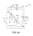
- Figure 8A is a cross-sectional side view of a forming station having a preform positioned therein of one embodiment of the present invention
- Figure 8B is a cross-sectional side view of the forming station of Figure 8A illustrating the formation of an elongated member by compression of one embodiment of the present invention
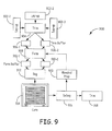
- Figure 9 illustrates a process layout of one embodiment of the present invention.
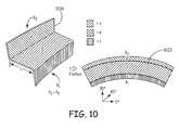
- Figure 10 illustrates a front perspective view of an elongated member illustrating different zones of one embodiment of the present invention
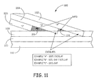
- Figure 11 illustrates fiber placement in a curved elongated member of one embodiment of the present invention.
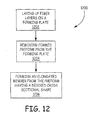
- Figure 12 illustrates a flow process diagram of one embodiment of the present invention.
- Embodiments of the present invention provide elongated composite members, generally referred to herein as elongated members, with varying cross-sectional shapes having corners that form the shapes that are generally free of wrinkles.
- a formed elongated member 100 having a desired shape is illustrated.
- Figure 1 illustrates the use of corners 104 and 106 to form what is commonly called "Z-shaped member.” That is, a cross-sectional shape of the elongated member 100 is commonly referred to as a "Z shape.”
- Figure 1 illustrates the inner radius R 1 is smaller than the outer radius R 0 at curves 104 and 106 (or bends) of the elongated member 100.
- a preform is made that includes ridges and/or grooves.
- the ridges and/or grooves are located where corners that define the cross-sectional shape are to be formed during the shaping of the elongated member.
- the use of the ridges and grooves provides relatively wrinkle free corners as illustrated in Figure 1 .
- FIG. 2A shows an end view of the forming plate 200 (or mandrel) illustrating that the forming plate 200 has a groove 202 and a ridge 204.
- the end view of the forming plate 200 illustrates the cross-sectional shape of the groove 202, in this embodiment, is a recessed arc and the cross-sectional shape of the ridge in this embodiment is an extended arc.
- the groove 202 and the ridge 204 each extend the length of the forming plate 200.
- a preform is formed, or laid up, over the forming plate 200.
- FIG. 8A illustrates an end view of an elongated member 220 (which is Z-shaped in this example) that is formed from a preform laid out on forming plate 200 of Figure 2A .
- the groove 202 of the forming plate 200 is used when forming curve 206 (or bend 206) in the Z-shaped elongated member 220 and the ridge 204 of the forming plate 200 is used when forming curve 208 (or bend 208) of the Z-shaped elongated member 220.
- the groove 202 and ridge 204 of the forming plate 200 provide a preform that accommodates the radii of curves 206 and 208 in the elongated member 220 to achieve curves free from wrinkles.
- One method of forming the elongated member 220 from a preform that is formed on the forming plate 200 is by compressing the preform on a forming tool.
- One compression method is further discussed below in regards to Figures 8A and 8B .
- Figures 3A and 3B illustrate another example of a forming plate 300 used in the forming of an elongated member 320.
- the forming plate 300 as illustrated in this end view of Figure 3A includes a relatively large ridge 302 having a first arcing termination end 308 and a second arcing termination end 310.
- corner 306 is formed with the use of first arcing termination end 308 of ridge 302 of the tool forming plate and corner 304 of the C-shaped elongated member 320 is formed with the use of the second arcing termination end 310 of ridge 302 of the forming plate 300.
- elongated member 320 would be formed from a preform laid up on forming plate 300.
- a forming plate 400 and an elongated member 402 that is made with use of forming plate 400 is illustrated in Figures 4A and 4B .
- Figure 4A an end view of forming plate 400 is illustrated having grooves 402 and 408 and ridges 404 and 408.
- corner 410 of elongated member 420 is formed with the use of groove 402 of forming plate 400
- corner 412 of the elongated member 420 is formed with the use of ridge 404 of forming plate 400
- corner 414 of elongated member 420 is formed with the use of ridge 406 of forming plate 400
- corner 416 of elongated member 420 is formed with the use of groove 408 of forming plate 400.
- a mandrel 500 used on one embodiment to make preforms is illustrated in the front perspective view of Figure 5 .
- the mandrel 500 includes connectors 504-1 and 504-2 used to move and secure the mandrel 500 at a give location.
- the mandrel 500 is simply placed face up on a support surface.
- connectors 504-1 and 504-2 are not needed.
- the mandrel 500 also includes a forming plate 502 upon which preforms are made.
- the plate 502 includes desired grooves 510 and ridges 512 that form the desired grooves 510 and ridges 512 in the preforms.
- the plate 502 allows for more than one preform to be laid up a time.
- the plate 502 forms a preform blank upon which 4 different curved preforms are created as discuss below.
- the preforms are formed with fiber placement (FP) technology.
- FP fiber placement
- An example of FP technology is illustrated in commonly assigned U.S. Patent No. 6,096,164 entitled “Multiple Axes Fiber Placement Machine” which is incorporated herein by reference.
- FP fiber placement
- FIG. 6 a front perspective view of the mandrel 500 having a nested preform blank 600 formed thereon is illustrated. Each preform in the nested preform blank 600 is formed with respective grooves 722 and ridges 724 as illustrated.
- Figures 7A through 7D One method of obtaining preforms 720 from the nested preform blank 600 is illustrated in Figures 7A through 7D.
- Figure 7A illustrates a top view of the nested preform blank 600 removed from plate 502 of the mandrel 500.
- the nested preform blank 600 is then placed on the pattern cutter 700 illustrated in the side view of Figure 7B .
- the pattern cutter 700 then trims the nested preform blank 600 to form the plurality of preforms 720 as illustrated in Figure 7C .
- the alignment grooves 726 are further cut out of the preforms as illustrate in Figure 7D .
- the alignment grooves 726 are used to align formed elongated members from the preforms 720 in select positions.
- the preforms 720 include the grooves 722 and ridges 724 formed by the mandrel 500.
- a preform 720 is placed in a forming station 800 that is used in one embodiment to shape the preform 720. As illustrated, the preform is placed on a forming tool 802 that has the desired cross-sectional shape. The preform 720 is aligned with the forming tool 802 such that groove 722 is aligned with outward corner 822 and ridge 724 is aligned with inward corner 824.
- the forming station 800 as illustrated includes a pressure box 804 that is attached to the forming tool 802. The preform 720 is positioned in the pressure box 804. Also included in the pressure box 804 is a bladder 806.
- the bladder 806 is made from an elastic material.
- the pressure box 806 includes two openings 808-1 and 809-2 in this embodiment that allow hot air to pass into the pressure box 804 to inflate the bladder 806.
- the hot air passing through openings 808-1 and 808-2 in the pressure box 804 causes the bladder 806 to compress the preform 720 on the forming tool 802 to form the desired cross-sectional shaped elongated member 820. This is illustrated in Figure 8B .
- the hot air is allowed to escape out the openings 808-1 and 808-2 which causes the bladder to retreat from the elongated member 820.
- the completed elongated member 820 is then removed from the forming station 800.
- the above embodiment uses a pressure box 804 to compress and form the elongated members 820, other techniques that compress the preforms 720 having ridges and grooves can be used to form elongated members 820.
- the forming tool is also a curing tool 802 that is heated. In this embodiment, the curing tool 802 is not only used to shape the elongated member 820 but is also used to cure the elongated member 820.
- the amount of time the formed elongated member 820 is maintained on the forming tool 802 and the temperature of the curing tool 802 is selected to achieve a desired curing of the elongated member.
- the heat and pressure applied to during the forming process should cause the elongated members to be consolidated enough that they may not require an autoclave to produce low void content parts.
- an Automatic Stiffener and Forming Machine is used to form the cross-sectional shape from a preform.
- ASFM Automatic Stiffener and Forming Machine
- the ASFM which may be a radial (ASFM-R) for a curved elongated members or a linear (ASFM-L) used for linear elongated members is used to compact the preform to form the desired cross-sectional shape in the elongated member.
- the preform is positioned on a shaped forming tool and rollers of the ASFM-R or ASFM-L are used to compress the preform on the forming tool to achieve the desired shape.
- FIG. 9 a process layout 900 illustrating one method of forming elongated members of an embodiment is illustrated.
- the process layout 900 starts with laying up preforms having the desired grooves and/or ridges on a mandrel at 902-1, 902-1 and 902-3. Hence more than one lay out station 902-1 through 902-3 can be used. This may be desired since the lay-up process will likely be the longest process in the process layout 900.
- the preforms maybe made from nested preform blanks 600. Once the lay up of the preforms has been completed, they are brought to a trim station 904 where they are trimmed as desired.
- trim buffers 906-1 and 906-2 are used to store the trimmed preforms for further processing.
- the trimmed preforms are then taken from the respective trim buffers 906-1 and 906-2 and shaped into elongated members in the form station 908.
- An example of a form station 908 is forming station 800 described and illustrated in regards to Figures 8A and 8B .
- the formed elongated members will be consolidated enough that they may not require an autoclave to produce low void content for most applications. Hence, as discussed above, in some embodiments, the elongated member is complete after the elongate member is formed.
- the elongated members may be cured in a conveyer oven or another type of curing system such as, but not limited to, batch curing in an autoclave as further illustrated in Figure 9 .
- the elongated members formed in the form station 908 are then stored in buffers 910-1 and 910-2 for further process.
- the further process in this embodiment includes placing the elongated members in vacuum bags at bag station 912 for further compression.
- the bagged elongated members are then placed in an autoclave at cure station 914. Once cured, the vacuum bags are then removed at the debag station 916. If further trimming of the elongated member is required, it takes place at trim station 918.
- the product is then complete.
- the mandrel used in the form station 908 in one embodiment is prepared for the next batch of elongated members in the mandrel prep station 920 as illustrated in Figure 9 .
- FIG 10 illustrates an elongated member 1000 formed with the process as described above.
- Elongated member 1000 is formed from a preform 1020 that is curved along its length into a Z-shape that could be used as a stiffener in the frame of an aircraft or any other application requiring the specific shape.
- zones A, B and C that make up the elongated member 1000 and radius' R 1 and R 2 .
- laying up preforms involves applying layers of fibers. Each fiber layer may have a different fiber orientation than another fiber layer. Common fiber orientations include 90 degree plies and minus and positive 45 degree plies although any orientation can be used and the present invention is not limited to just 90 degree and 45 degree plies.
- Fiber orientation refers to the angle upon which the fibers extend from an edge of elongated member such as a radius edge of a curved elongated member.
- an edge of elongated member such as a radius edge of a curved elongated member.
- current ASMF-R has limitations to the length L of zone B in curved elongated members with 90 degree plies.
- the length L of zone B of an elongated member 1000 that is curved along its length that is formed only with an ASMF-R has to be under a certain distance when using 90 degree plies (and to a lesser extend 45 degree plies) or bunching/wrinkling in zone C or gaps/tearing in zone A will occur using an ASMF-R.
- curved elongated members having length L greater than the current maximum distance on the ASFM-R in zone B is possible.
- Processes set out above are further enhanced to prevent bunching/wrinkling and gaps/tearing in elongated curved members by dropping and adding tows during the fiber placement process of 90 degree plies and by utilizing tow steering along with dropping and adding tows for 45 degree plies.
- Examples of adding and dropping tows 1100 that is used in some curved embodiments are illustrated in Figure 11 .
- a first group of parallel tows, 1108, 1110 and 1112 extend at a first direction of orientation.
- a second group of parallel tows 1102, 1104 and 1106 having a second direction of orientation are coupled to the first group of tows 1108, 1110 and 1112.
- This example illustrates how tow 1102 labeled "A" overlaps tow 1108 100 %, how tow 1104 labeled "B” overlaps tow 1108 50 % and how tow 1106 labeled "C” overlaps tow 1108 at 0 %.
- the example also illustrates, gaps 1114 and 1116 that occur because of the different orientations and different overlap arrangements.
- different overlaps having different gaps can be achieved by adding and dropping tows to achieve a composite structure having desired characteristics.
- the ability to control the amount of overlap anywhere between the "A" 100% overlap and "C" 0% gap is common with current fiber placement machines and machine control software.
- the tow steering can be used in some embodiments to positions the tows on a desired curved path.
- Adding tows, dropping tows or tow steering in some embodiments can prevent undesired results in curved elongated members such as bunching/wrinkling in zone C or gaps/tearing in zone A of the elongated curved member 1000 of Figure 10 .
- the process starts by laying up fiber layers (or ply layers) on a forming plate to form a preform (1202).
- a preform 1202
- nested blanks of preforms are laid up at the same time on a mandrel having a forming plate.
- the tows or fibers are laid down with techniques that prevents bunching, wrinkling, gaps and tearing. The techniques may include as discussed above, tow steering and dropping and adding tows depending on the orientation of the tows.
- the lay up of the preform in one embodiment is done with fiber placement technology.
- unidirectional tape unidirectional tape
- Uni-tape has fibers or tows placed on a backing (tape) that are all in the same orientation (for example, but not limited to, 90 degrees, 45 degrees or 30 degrees).
- Tows in one embodiment are layered on the forming plate to form a laminate that is the preform. Each layer, which is heated to enhance tackiness between layers, is typically pressed onto the prior layer with the use of rollers and the like.
- the forming plate upon which the preform is laid up includes grooves and ridges that define corners or bends of the formed elongated member. Examples, of grooves and ridges in a preform are illustrated in Figures 2A , 3A , 4A and 8A as discussed above.
- the preform is removed from the forming plate (1204) as further illustrated in flow process diagram of Figure 12 .
- Each preform is then formed into an elongated member having a desired cross-sectional shape (1206). Examples of cross-sectional shapes are illustrated in Figures 2B , 3B and 4B as discussed above.
- the preform is compressed over a forming tool to achieve the desired shape, with the grooves and ridges in the preform aligning with corners of the forming tool.
- the forming tool is heated to cure the elongated member once it is formed.
- forming and curing is done in one step.
- ASFM-R or ASFM-L are used to form the preform into the desired cross-sectional shape.
Landscapes
- Engineering & Computer Science (AREA)
- Mechanical Engineering (AREA)
- Chemical & Material Sciences (AREA)
- Composite Materials (AREA)
- Moulding By Coating Moulds (AREA)
Applications Claiming Priority (1)
| Application Number | Priority Date | Filing Date | Title |
|---|---|---|---|
| US12/483,613 US8585952B2 (en) | 2009-06-12 | 2009-06-12 | Pressure molded preform process for composite structures |
Publications (1)
| Publication Number | Publication Date |
|---|---|
| EP2261006A2 true EP2261006A2 (fr) | 2010-12-15 |
Family
ID=42799794
Family Applications (1)
| Application Number | Title | Priority Date | Filing Date |
|---|---|---|---|
| EP10160461A Withdrawn EP2261006A2 (fr) | 2009-06-12 | 2010-04-20 | Procédé de préforme moulée sous pression pour structures composites |
Country Status (3)
| Country | Link |
|---|---|
| US (1) | US8585952B2 (fr) |
| EP (1) | EP2261006A2 (fr) |
| CA (1) | CA2703094A1 (fr) |
Cited By (6)
| Publication number | Priority date | Publication date | Assignee | Title |
|---|---|---|---|---|
| WO2012136222A1 (fr) * | 2011-04-06 | 2012-10-11 | Vestas Wind Systems A/S | Procédé et appareil de préparation d'une pièce en composite renforcé par fibres |
| EP2596942A1 (fr) * | 2011-11-23 | 2013-05-29 | Airbus Operations Limited | Procédé de commande de pli/ride et outil à cet effet |
| ES2432090R1 (es) * | 2012-03-26 | 2014-08-12 | Airbus Operations, S.L. | Procedimiento de fabricación de piezas realizadas en material compuesto y dispositivo empleado. |
| DE102015201264A1 (de) * | 2015-01-26 | 2016-07-28 | Bayerische Motoren Werke Aktiengesellschaft | Verformvorrichtung zum Verformen eines vorimprägnierten Faserverbundhalbzeuges sowie Verfahren zum Verformen eines vorimprägnierten Faserverbundhalbzeuges |
| ITUA20161549A1 (it) * | 2016-03-10 | 2017-09-10 | Composite Solutions Srl | Metodo di formatura di un corpo a guscio e corpo a guscio ottenuto con tale metodo |
| WO2017153965A1 (fr) * | 2016-03-10 | 2017-09-14 | Composite Solutions S.R.L. | Procédé de formation d'un corps de coque et corps de coque ainsi obtenu |
Families Citing this family (10)
| Publication number | Priority date | Publication date | Assignee | Title |
|---|---|---|---|---|
| FR2987779A1 (fr) * | 2012-03-12 | 2013-09-13 | Airbus Operations Sas | Procede de realisation d'une piece en materiau composite et outillage pour sa mise en oeuvre |
| FR2995244B1 (fr) * | 2012-09-07 | 2014-10-10 | Airbus Operations Sas | Procede de realisation d'un profile en materiau composite presentant un angle rentrant a partir d'un empilage de couches de fibres |
| US10059065B2 (en) * | 2016-04-06 | 2018-08-28 | Spirit Aerosystems, Inc. | Method for eliminating radius wrinkles in composite laminates |
| US10611097B2 (en) | 2016-05-24 | 2020-04-07 | General Electric Company | Methods and systems including pressurized housings for forming materials |
| US10780614B2 (en) | 2016-05-24 | 2020-09-22 | General Electric Company | System and method for forming stacked materials |
| JP7096106B2 (ja) | 2018-08-28 | 2022-07-05 | 株式会社Subaru | プリフォーム賦形方法及び複合材成形方法 |
| JP7193282B2 (ja) * | 2018-09-14 | 2022-12-20 | 株式会社Subaru | プリフォーム賦形方法及び複合材成形方法 |
| WO2020081348A1 (fr) | 2018-10-15 | 2020-04-23 | General Electric Company | Systèmes et procédés d'élimination automatisée de film |
| US11691356B2 (en) | 2021-02-08 | 2023-07-04 | General Electric Company | System and method for forming stacked materials |
| CN113695709A (zh) * | 2021-09-06 | 2021-11-26 | 上海航天精密机械研究所 | 一种设计尾坯的航天承力结构电弧熔丝增材路径规划方法 |
Citations (2)
| Publication number | Priority date | Publication date | Assignee | Title |
|---|---|---|---|---|
| US6096164A (en) | 1990-12-19 | 2000-08-01 | Alliant Techsystems Inc. | Multiple axes fiber placement machine |
| US7513769B2 (en) | 2003-08-01 | 2009-04-07 | Alliant Techsystems Inc. | Apparatus and methods for forming composite stiffeners and reinforcing structures |
Family Cites Families (5)
| Publication number | Priority date | Publication date | Assignee | Title |
|---|---|---|---|---|
| US3039372A (en) * | 1958-06-12 | 1962-06-19 | Int Paper Box Machine Co | Creasing apparatus, method and product |
| US3615149A (en) * | 1968-09-20 | 1971-10-26 | Joseph G Malone | Heat insulating product |
| US5145621A (en) * | 1990-04-20 | 1992-09-08 | General Electric Company | Crossover mold tool for consolidating composite material |
| US5648109A (en) * | 1995-05-03 | 1997-07-15 | Massachusetts Institute Of Technology | Apparatus for diaphragm forming |
| ES2315580T3 (es) * | 2004-02-13 | 2009-04-01 | Saab Ab | Procedimiento para la fabricacion de un articulo de material compuesto. |
-
2009
- 2009-06-12 US US12/483,613 patent/US8585952B2/en active Active
-
2010
- 2010-04-20 EP EP10160461A patent/EP2261006A2/fr not_active Withdrawn
- 2010-05-04 CA CA2703094A patent/CA2703094A1/fr not_active Abandoned
Patent Citations (2)
| Publication number | Priority date | Publication date | Assignee | Title |
|---|---|---|---|---|
| US6096164A (en) | 1990-12-19 | 2000-08-01 | Alliant Techsystems Inc. | Multiple axes fiber placement machine |
| US7513769B2 (en) | 2003-08-01 | 2009-04-07 | Alliant Techsystems Inc. | Apparatus and methods for forming composite stiffeners and reinforcing structures |
Cited By (9)
| Publication number | Priority date | Publication date | Assignee | Title |
|---|---|---|---|---|
| WO2012136222A1 (fr) * | 2011-04-06 | 2012-10-11 | Vestas Wind Systems A/S | Procédé et appareil de préparation d'une pièce en composite renforcé par fibres |
| EP2596942A1 (fr) * | 2011-11-23 | 2013-05-29 | Airbus Operations Limited | Procédé de commande de pli/ride et outil à cet effet |
| US9067371B2 (en) | 2011-11-23 | 2015-06-30 | Airbus Operations Limited | Wrinkle control method and tool therefor |
| ES2432090R1 (es) * | 2012-03-26 | 2014-08-12 | Airbus Operations, S.L. | Procedimiento de fabricación de piezas realizadas en material compuesto y dispositivo empleado. |
| US9782958B2 (en) | 2012-03-26 | 2017-10-10 | Airbus Operations S.L. | Method and device for manufacturing composite material parts |
| DE102015201264A1 (de) * | 2015-01-26 | 2016-07-28 | Bayerische Motoren Werke Aktiengesellschaft | Verformvorrichtung zum Verformen eines vorimprägnierten Faserverbundhalbzeuges sowie Verfahren zum Verformen eines vorimprägnierten Faserverbundhalbzeuges |
| DE102015201264B4 (de) * | 2015-01-26 | 2019-10-02 | Bayerische Motoren Werke Aktiengesellschaft | Verformvorrichtung zum Verformen eines vorimprägnierten Faserverbundhalbzeuges sowie Verfahren zum Verformen eines vorimprägnierten Faserverbundhalbzeuges |
| ITUA20161549A1 (it) * | 2016-03-10 | 2017-09-10 | Composite Solutions Srl | Metodo di formatura di un corpo a guscio e corpo a guscio ottenuto con tale metodo |
| WO2017153965A1 (fr) * | 2016-03-10 | 2017-09-14 | Composite Solutions S.R.L. | Procédé de formation d'un corps de coque et corps de coque ainsi obtenu |
Also Published As
| Publication number | Publication date |
|---|---|
| CA2703094A1 (fr) | 2010-12-12 |
| US20100316837A1 (en) | 2010-12-16 |
| US8585952B2 (en) | 2013-11-19 |
Similar Documents
| Publication | Publication Date | Title |
|---|---|---|
| US8585952B2 (en) | Pressure molded preform process for composite structures | |
| CN111452947B (zh) | 成形复合桁条 | |
| EP1393875B1 (fr) | Procédé de fabrication et outillage pour la fabrication de pièces composites | |
| EP2648893B1 (fr) | Procédé pour former une structure composite comportant un rebord | |
| EP1910062B1 (fr) | Dispositif et procede pour fabriquer un element structurel composite courbe | |
| US10207466B2 (en) | Apparatus for forming thick thermoplastic composite structures | |
| EP2561979B1 (fr) | Procédé de formation de raidisseurs composites profilés | |
| EP2539134B1 (fr) | Moulage continu de stratifiés thermoplastiques | |
| US6355133B1 (en) | Forming reinforcing components | |
| US9724891B2 (en) | Bead-stiffened composite parts | |
| CN101795851B (zh) | 由复合材料制造的复杂几何体和所述几何体的成型方法 | |
| EP3838569B1 (fr) | Procédé de formation de préformes composites à fibres | |
| WO2014200675A1 (fr) | Procédé et appareil de fabrication de lisses composites | |
| CN110884161B (zh) | 复合材料的弯曲欧米茄桁条和z形桁条制造方法以及具有曲率的复合材料加筋板的制造方法 | |
| US9321221B2 (en) | Continuous preform device for composite stringer | |
| CN115723351A (zh) | 用于成型高轮廓复合结构的成型设备及相关方法 | |
| CN108081632B (zh) | 用于制造多层纤维结构的方法和工具系统 | |
| US20220204182A1 (en) | Process for producing a component having a thermoplastic fiber composite and components made by the process | |
| EP3744511B1 (fr) | Station de formation composite | |
| HK1109601B (en) | Curved composite structural element fabricating device and method |
Legal Events
| Date | Code | Title | Description |
|---|---|---|---|
| PUAI | Public reference made under article 153(3) epc to a published international application that has entered the european phase |
Free format text: ORIGINAL CODE: 0009012 |
|
| AK | Designated contracting states |
Kind code of ref document: A2 Designated state(s): AT BE BG CH CY CZ DE DK EE ES FI FR GB GR HR HU IE IS IT LI LT LU LV MC MK MT NL NO PL PT RO SE SI SK SM TR |
|
| AX | Request for extension of the european patent |
Extension state: AL BA ME RS |
|
| STAA | Information on the status of an ep patent application or granted ep patent |
Free format text: STATUS: THE APPLICATION IS DEEMED TO BE WITHDRAWN |
|
| 18D | Application deemed to be withdrawn |
Effective date: 20121101 |