EP2261016B1 - Presse - Google Patents
Presse Download PDFInfo
- Publication number
- EP2261016B1 EP2261016B1 EP10178765.3A EP10178765A EP2261016B1 EP 2261016 B1 EP2261016 B1 EP 2261016B1 EP 10178765 A EP10178765 A EP 10178765A EP 2261016 B1 EP2261016 B1 EP 2261016B1
- Authority
- EP
- European Patent Office
- Prior art keywords
- gib
- slide
- spherical
- frame
- clearance
- Prior art date
- Legal status (The legal status is an assumption and is not a legal conclusion. Google has not performed a legal analysis and makes no representation as to the accuracy of the status listed.)
- Expired - Lifetime
Links
- 230000000717 retained effect Effects 0.000 claims 2
- 230000000295 complement effect Effects 0.000 claims 1
- 230000008901 benefit Effects 0.000 description 10
- 238000003825 pressing Methods 0.000 description 8
- 238000013461 design Methods 0.000 description 6
- 230000001627 detrimental effect Effects 0.000 description 3
- 239000010687 lubricating oil Substances 0.000 description 3
- 238000004519 manufacturing process Methods 0.000 description 3
- 239000012528 membrane Substances 0.000 description 3
- 238000012986 modification Methods 0.000 description 3
- 230000004048 modification Effects 0.000 description 3
- XEEYBQQBJWHFJM-UHFFFAOYSA-N Iron Chemical compound [Fe] XEEYBQQBJWHFJM-UHFFFAOYSA-N 0.000 description 2
- 238000010276 construction Methods 0.000 description 2
- 230000033001 locomotion Effects 0.000 description 2
- 230000007246 mechanism Effects 0.000 description 2
- 238000000034 method Methods 0.000 description 2
- 239000003921 oil Substances 0.000 description 2
- 229910000881 Cu alloy Inorganic materials 0.000 description 1
- 239000004809 Teflon Substances 0.000 description 1
- 229920006362 Teflon® Polymers 0.000 description 1
- 230000006978 adaptation Effects 0.000 description 1
- 230000001668 ameliorated effect Effects 0.000 description 1
- 230000009286 beneficial effect Effects 0.000 description 1
- 230000015572 biosynthetic process Effects 0.000 description 1
- 230000015556 catabolic process Effects 0.000 description 1
- 230000001419 dependent effect Effects 0.000 description 1
- 238000011161 development Methods 0.000 description 1
- 230000018109 developmental process Effects 0.000 description 1
- 239000013013 elastic material Substances 0.000 description 1
- 229910052742 iron Inorganic materials 0.000 description 1
- 238000005461 lubrication Methods 0.000 description 1
- 238000003754 machining Methods 0.000 description 1
- 238000012423 maintenance Methods 0.000 description 1
- 239000000463 material Substances 0.000 description 1
- 239000002184 metal Substances 0.000 description 1
- 229910052751 metal Inorganic materials 0.000 description 1
- 238000005555 metalworking Methods 0.000 description 1
- 238000012545 processing Methods 0.000 description 1
- 230000008439 repair process Effects 0.000 description 1
- 238000005728 strengthening Methods 0.000 description 1
Images




Classifications
-
- F—MECHANICAL ENGINEERING; LIGHTING; HEATING; WEAPONS; BLASTING
- F16—ENGINEERING ELEMENTS AND UNITS; GENERAL MEASURES FOR PRODUCING AND MAINTAINING EFFECTIVE FUNCTIONING OF MACHINES OR INSTALLATIONS; THERMAL INSULATION IN GENERAL
- F16C—SHAFTS; FLEXIBLE SHAFTS; ELEMENTS OR CRANKSHAFT MECHANISMS; ROTARY BODIES OTHER THAN GEARING ELEMENTS; BEARINGS
- F16C29/00—Bearings for parts moving only linearly
- F16C29/001—Bearings for parts moving only linearly adjustable for alignment or positioning
-
- B—PERFORMING OPERATIONS; TRANSPORTING
- B30—PRESSES
- B30B—PRESSES IN GENERAL
- B30B15/00—Details of, or accessories for, presses; Auxiliary measures in connection with pressing
- B30B15/04—Frames; Guides
- B30B15/041—Guides
Definitions
- the present invention relates to a slide guide device for a press. More specifically, the present invention relates to a slide guide device that guides a slide with high precession during pressing operations.
- a press includes a slide.
- a copper alloy liner serves as a slide surface.
- the press includes an iron gib disposed on a frame opposite the slide surface. During operation, the liner and the gib slide against each other to guide the slide along the frame.
- a lubricating oil lubricates the sliding surfaces.
- the lubricating oil forms an oil membrane between the liner and the gib to minimize friction and wear.
- JP 2000 193782 A partially overcomes this difficulty using a spherical surface block and a gib sliding against each other along a liner that has a V-shaped sliding surface.
- aligning the V shape of the spherical surface block and the gib is difficult.
- this design ultimately during high loads the V-shaped surface of the spherical surface block spreads, causing damaging contact, costly repair and downtime.
- US 5 775 212 A describes a guide gib structure for a press slide of a mechanical press for metal working.
- the structure may avoid a screw of a gib being loosened and easily adjust a clearance between the gib and a guide surface.
- DE 2 218 438 A1 describes a guide assembly including a slide having a shape surrounding columns 2 and 3, and a bush 11 and an intermediate element 12 that are provided on a contacting surface with the columns 2 and 3 for guiding the slide. Since the intermediate element 12 is made of an elastic material, the element is deformed when an eccentric load is applied.
- the present invention provides a slide guide device which improves pressing precision and accuracy.
- the present invention provides a slide guide device which compensates for eccentric forces during pressing and eliminates eccentric contact between each sliding surface.
- the present invention provides a slide guide device that employs a gib structure using a rotatable element to maintain uniform contact between each sliding surface.
- the present invention provides a slide guide device that is easily adjustable to set and fix an optimum gap between sliding surfaces.
- the present invention provides a slide guide device which compensates for both lateral and eccentric loads during pressing operations and allows for simple assembly.
- a press 50 includes a frame 1.
- Frame 1 supports a bed 51.
- Frame 1 includes a left side frame and a right side frame (both not numbered).
- a pair of stays 19 join the left side frame and the right side frame. Stays 19 provide additional stability to press 50 during operation.
- a bolster 3 is disposed on bed 51 opposite slide 2a.
- a slide 2a is slidably operable along frame 1 relative to bolster 3 and to bed 51.
- Slide 2a is connected to a connecting rod 4 and a crank shaft (not shown). Connecting rod 4 and the crank shaft form a crank mechanism for operating slide 2a. During operation, the crank mechanism reciprocates slide 2a relative to bolster 3.
- a pair of gibs 5a, 6a on frame 1 are located on respective left and right side frame members opposite slide 2a.
- Spherical shoes 7, 8, 9, 10 are disposed on slide 2a, as will be explained.
- Spherical shoes 7, 8 and gib 5a are on a first side of slide 2a.
- Spherical shoes 9, 10 and gib 6a are on the second side of slide 2a.
- gibs 5a, 6a engage respective spherical shoes 7, 8, 9, 10 to guide slide 2a upward and downward on frame 1.
- a pair of gib holders 13, 14 on frame 1 secure gib 5a relative to slide 2a, as will be explained.
- An engagement section 13a is on gib holder 13.
- An engagement section 14a is on gib holder 14.
- Engagement sections 13a, 14a engage respective grooves (shown but not numbered) on frame 1.
- Engagement sections 13a, 14a align respective gib holders 13, 14 to frame 1.
- Bolts (not shown) secure gib holders 13, 14 to frame 1.
- a hollow screw 15' is screwed into gib holder 13.
- a hollow screw 15" is screwed into gib holder 14.
- a bolt 16' extends through hollow screw 15'.
- a bolt 16" extends through hollow screw 15".
- Bolts 16', 16" secure hollow screws 15', 15" to respective gib holders 13, 14.
- An end of bolt 16" extends through hollow screw 15" in gib holder 14.
- a wedge 12 threadably engages the end of bolt 16".
- Bolt 16" slidably retains wedge 12 relative to gib holders 13, 14.
- hollow screw 15" and bolt 16" threadably control and position wedge 12 relative to gib holder 14.
- An end of bolt 16' extends through hollow screw 15' in gib holder 13.
- Gib 5a threadably engages the end of bolt 16'.
- Bolt 16' slidably retains gib 5a relative to gibe holder 13.
- hollow screw 15' and bolt 16' threadably control and position gib 5a relative to gib holder 13.
- Wedge 12 between gib 5a and frame 1, has a tapered shape that matches a tapered shape of gib 5a.
- Wedge 12 supports gib 5a.
- Wedge 12 and gib 5a slidably engage and allow easy adjustment of gib 5a relative to slide 2a. After assembly and adjustment, bolts 17 secure wedge 12 and gib 5a to frame 1.
- a liner 11 is secured with at least one screw (not shown) on an outer surface of gib 5a between gib 5a and slide 2a.
- Liner 11 is typically a Teflon-based impregnated porous bi-metal, but may be any convenient wear resistant and slippery material.
- liner 11 is plate-shaped affixed vertically along gib 5a.
- At least one spherical cavity 18 is on slide 2a opposite gib 5a.
- Spherical cavity 18 has a concave hemispheric shape.
- Spherical shoe 7 is positioned in spherical cavity 18.
- Spherical shoe 7 has a convex hemispheric section which matches the concave hemispheric shape of spherical cavity 18.
- Spherical shoe 7 has a flat section opposite the hemispheric section. During assembly, the flat section of spherical shoe 7 contacts liner 11. During operation, the flat section of spherical shoe 7 slidably contacts liner 11. During operation, when eccentric forces occur, the hemispheric section of spherical shoe 7 adjusts relative to spherical cavity 18 to maintain the flat section parallel to liner 11 and gib 5a, thereby eliminating line contacts.
- Gib 6a is fixed relative to frame 1. In combination, gib 5a and gib 6a increase the operational precision of press 50 and guide slide 2a during a slide cycle.
- An engagement section 14a' on gib 6a fits into at least one groove formed (shown but not numbered) in frame 1. During assembly, at least one additional bolt 17 secures gib 6a to frame 1.
- Gibs 5a, 6a each include two corner guide surfaces (shown but not numbered) opposite slide 2a.
- the guide surfaces on gib 5a are opposite two respective corners of slide 2a.
- the guide surfaces on gib 6a are opposite the respective other two corners of slide 2a.
- the four corners of slide 2a operate parallel to their respective corner guide surface of gibs 5a, 6a.
- a set of shoes 23 is affixed to slide 2a on each corner of slide 2a.
- Shoes 23 are opposite respective corner guide surface on gibs 5a, 6a.
- slide 2a is easily and guidably restrained along a left/right axis by spherical shoes 7, 8, 9, and 10, and along a forward/back axis by shoes 23.
- precision operation is easily achieved without increased operational costs or the need for precision machining.
- bolt 17 secures gib 6a to frame 1.
- Spherical shoes 7, 8, 9, and 10 are installed within their respective cavities 18 on opposite sides of slide 2a.
- the now-assembled slide 2a is placed in frame 1 along gib 6a.
- Wedge 12 and gib 5a are assembled opposite slide 2.
- Wedge 12 and gib 5a are positioned and adjusted using respective hollow screws 15', 15" and bolts 16', 16" while maintaining even contact between liners 11 and spherical shoes 7, 8, 9, and 10.
- additional bolts 17 secure wedge 12 and gib 5a to frame 1.
- a first example useful for understanding the invention includes a gib holder 14' and gib holders 13, 14. Engagement section 13a is located on gib holder 13. Engagement section 14a is located on gib holder 14. An engagement section 14a" is located on gib holder 14'.
- Engagement sections 13a, 14a engage groves (shown but not numbered) on one side of frame 1. Engagement sections 13a, 14a align respective gib holders 13, 14 to frame 1. Gib holders 13, 14 align and support a gib 5b, relative to frame 1. Engagement section 14a" aligns gib holder 14' with frame 1. Gib holder 14' aligns and supports a gib 6b relative to frame 1. During operation, gibs 5b, 6b precisely and reliably guide slide 2b along frame 1, as will be explained.
- Engagement section 14a" engages an engagement groove (shown but not numbered) on frame 1 opposite engagement sections 13a, 14a.
- a hollow screw 15"' threadably engages gib holder 14'.
- a bolt 16"' is inserted into hollow screw 15"'.
- An end of bolt 16"' threadably engages gib 6b to allow adjustment of gib 6b relative to frame 1.
- at least one bolt 17 fixes gib 6b to frame 1.
- An abutting section 6a' on frame 1 opposite gib 6b resists pressure from bolt 16"' and supports gib 6b during assembly and operation.
- hollow screw 15' is screwed into gib holder 13.
- Hollow screw 15" is screwed into gib holder 14.
- Bolt 16' is inserted into hollow screw 15'.
- Bolt 16" is inserted into hollow screw 15".
- An end of bolt 16' screws into wedge 12 to join gib holder 13 to wedge 12. During assembly, an end of hollow screw 15' helps to position wedge 12. Bolt 16' secures hollow screw 15' to gib holder 13. In combination, hollow screw 15' and bolt 16' secure wedge 12 relative to gib holder 13.
- An end of bolt 16" is screwed into gib 5b to join gib holder 14 to gib 5b.
- an end of hollow screw 15" positions gib 5b.
- Bolt 16" secures hollow screw 15" to gib 5b.
- hollow screw 15" and bolt 16" secure gib 5b relative to gib holder 14, wedge 12 and slide 2b. Once wedge 12 and gib 5b are positioned, at least one bolt 17 secures gib 5b and wedge 12 to frame 1.
- a first pair of liners 11, 11 are secured to gib 5b opposite slide 2b.
- a second pair of liners (not shown) is secured to gib 6b in a similar manner.
- Liners 11, 11 have plate-like shapes and are vertically affixed along gibs 5b, 6b.
- Each gib 5b, 6b has two contact surfaces extending parallel along slide 2b. Liners 11 are located on the respective contact surface along gib 5b and 6b.
- Slide 2b has contact surfaces corresponding to the contact surfaces on gibs 5b, 6b. The contact surfaces on gibs 5b, 6b and slide 2b slide parallel to each other to allow easy and precise movement of slide 2b.
- pairs of spherical shoes 7, 7 and 9, 9 rotatably fit within corresponding spherical cavities 18 on slide 2b.
- the flat sections of spherical shoes 7, 7 contact liners 11 on gib 5b and slide freely.
- the flat sections of spherical shoes 9, 9 similarly contact liners 11 on gib 6b and slides freely.
- the spherical surface of spherical shoes 7, 7, and 9, 9 rotate within cavities 18 to allow the entire surface of their respective flat sections to remain parallel to their respective liners 11.
- the contact surfaces on gibs 5b, 6b correspond to the surfaces of each pair of liners 11, 11.
- An angle alpha ( ⁇ ) is an angle between the contact surfaces of the liners 11.
- Angle alpha ( ⁇ ) is selected based upon the state of eccentric loads during pressing operations.
- pressure (force) from slide 2b passes through respective spherical shoes 7, 8, 9, and 10 and is transferred to the contact surface of liners 11.
- the forces acting on each contact surface can be analyzed, based on the slope of the contact surface.
- the forces can be broken down into a force providing restriction along a left-right axis of slide 2b and a force providing restriction along a forward-backward axis of slide 2b.
- slide 2b is restricted along the left-right axis and the forward-backward axis by gibs 5b, 6b.
- angle alpha ( ⁇ ) is approximately 120 deg.
- the eccentric load along the left-right axis of slide 2b is larger than the eccentric load along the front-back axis.
- the projected area along the left-right axis of the guide surfaces is greater than that along the front-back axis.
- angle alpha ( ⁇ ) is 120 deg, the cosine and sine functions indicate that the ratio of projected areas is 3 (square root of 3): 1, i.e., approximately 1.7 : 1.
- a second example useful for understanding the invention includes a pair of gibs 5c, 6c.
- Gibs 5c, 6c have a generally concave shape relative to a slide 2c.
- gibs 5c, 6c guide a slide 2c during pressing operations.
- angle alpha ( ⁇ ) between respective liners 11, 11 is also approximately 120 deg.
- angle alpha ( ⁇ ) between respective liners 11, 11 is also approximately 120 deg.
- the first example provides greater compensation for thermal deformation.
- the example is easily adaptable to both precision pressing operations and variable operating environments.
- a third example useful for understanding the invention includes a slide 2d operating between a pair of gibs 5d, 6d.
- a pair of bolt 17, 17 secures respective gib 5d, 6d to frame 1 on opposite sides of slide 2d.
- a set of screws (not shown) secure a set of liners 11, 11 to gib 6d.
- Another set of screws (not shown) secure a second set of liners 11, 11 to gib 5d.
- a bolt 22 secures each block 21, 21 to each side of slide 2d opposite respective gibs 5d, 6d.
- Spherical cavities 18, 18 are disposed in respective blocks 21, 21.
- a spherical shoe 20 rotatably fits within each block 21.
- a flat sections on each spherical shoe 20, 20 allows sliding contact with respective liners 11, 11 on each gib 5d, 6d, as will be explained.
- gibs 5d, 6d and wedge 12 are narrower than in the previous embodiment and examples.
- gib holders 13, 14 are smaller in overall dimension.
- gib 6d sits in a groove (shown but not numbered) in frame 1.
- a single bolt 17 threadably secures gib 6d to frame 1 opposite slid 2d.
- a single bolt 17 similarly secures and fixes wedge 12 and gib 5d to frame 1.
- An assembly method for the third example is similar to the assembly methods for the first and second examples.
- bolts 22, 22 secure respective blocks 21, 21 to slide 2d.
- Spherical shoes 20, 20 are then inserted into respective cavities 18, 18.
- Gib 6 is secured to frame 1 and receives the assembled slide 2d.
- Gib holders 13, 14, wedge 12 and gib 5 are installed and adjusted.
- bolts 17 secure wedge 12 and gib 5d to frame 1.
- gibs 5d, 6d are formed in a general 'V-shape.
- a liner 11 is positioned on each side of the V-shape.
- Each shoe 20 provides two corresponding contact surfaces opposite each liner 11.
- An angle beta ( ⁇ ) is defined between each side of the V-shape. Angle beta ( ⁇ ) is approximately 120 degrees.
- each shoe 20 replaces previous multiple shoes thereby reducing cost while maintaining precision.
- the multiple spherical shoes from the first and second examples are moved as close together as possible and combined.
- the third example is particularly advantageous for providing precision operations where space is limited and press 50 or a slide 2d must be small.
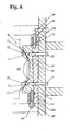
- the combination of at least one spherical shoe 7-9 having a flat guide surface sliding along a corresponding gib operates as an easy means for eliminating eccentric force and slide misalignment.
- the present design allows easy adaptation to a variety of production sizes, processing needs, and temperature gradients all while maintaining high precision, simple manufacture, and simple assembly.
- the present design also easily compensates for eccentric forces placed on the slide during regular operation.
- the spherical shoes, corresponding cavities, and angular gib faces easily compensate for any eccentric force and maintain parallel operation. As a result, equipment life is extended, maintenance costs reduced, and on-stream time maximized.
- a nail, a screw, and a bolt may not be structural equivalents in that a nail relies entirely on friction between a wooden part and a cylindrical surface, a screw's helical surface positively engages the wooden part, and a bolt's head and nut compress opposite sides of at least one wooden part, in the environment of fastening wooden parts, a nail, a screw, and a bolt may be readily understood by those skilled in the art as equivalent structures.
Landscapes
- Engineering & Computer Science (AREA)
- General Engineering & Computer Science (AREA)
- Mechanical Engineering (AREA)
- Presses And Accessory Devices Thereof (AREA)
Claims (3)
- Presse (50), comprenant :un châssis (1) ;une glissière (2a) ;une première cavité sphérique (18) sur un premier côté de ladite glissière (2a) ;un premier patin sphérique (7) ;un premier lardon (5a) disposé sur ledit châssis (1) opposé à ladite glissière (2a) et à ladite première cavité sphérique (18) ;une première surface de coulissement sur ledit premier lardon (5a) ;un ensemble de surfaces de guidage d'angle fournies audit premier lardon (5a) ; etun ensemble de patins (23) fixés à ladite glissière (2a) opposés à une surface de guidage d'angle respective ;dans laquelle ledit premier patin sphérique (7) comprend :une première surface sphérique ; etune première surface de contact plate opposée à ladite première surface sphérique, le premier patin sphérique (7) étant retenu en rotation dans ladite première cavité sphérique (18) ;ladite première surface de contact plate est alignée en rotation avec ladite première surface de coulissement ; etladite glissière (2a) est guidée et alignée avec ledit premier lardon (5a) durant un cycle,empêchant ainsi un désalignement en coulissement excentrique durant ledit cycle et augmentant une précision de presse, oùladite presse (50) comprend en outre :une deuxième cavité sphérique (18) sur un deuxième côté de ladite glissière ;un deuxième patin sphérique (9) ;un deuxième lardon (6a) disposé sur ledit châssis (1) opposé à ladite glissière (2a) et à ladite deuxième cavité sphérique (18) ;une deuxième surface de coulissement sur ledit deuxième lardon (6a) ;un ensemble de surfaces de guidage d'angle fournies audit deuxième lardon (6a) ; etun ensemble de patins (23) fixés à ladite glissière (2a) opposés à une surface de guidage d'angle respective ;dans laquelle ledit deuxième patin sphérique (9) comprend :une deuxième surface sphérique ; etune deuxième surface de contact plate opposée à ladite deuxième surface sphérique, le deuxième patin sphérique (9) étant retenu en rotation dans ladite deuxième cavité sphérique (18) ;ladite deuxième surface de contact plate est alignée en rotation avec ladite deuxième surface de coulissement ; etladite glissière (2a) est guidée et alignée avec ledit deuxième lardon (6a) durant ledit cycle,dans laquelle lesdites première et deuxième surfaces de coulissement sont perpendiculaires à un axe reliant les première et deuxième cavités sphériques (18), etdans laquelle lesdites surfaces de guidage d'angle fournies aux premier et deuxième lardons (5a, 6a) sont parallèles à un axe reliant les première et deuxième cavités sphériques (18).
- Presse (50) selon la revendication 1, comprenant en outre :au moins un premier jeu entre ladite première surface de contact plate et ladite première surface de coulissement ;au moins un deuxième jeu entre ladite deuxième surface de contact plate et ladite deuxième surface de coulissement ; etun moyen pour fixer et ajuster en coulissement ledit premier et ledit deuxième jeu et retenir chacun dudit premier et dudit deuxième jeu respectif au niveau d'un jeu optimum sélectionné, maintenant ainsi un alignement de ladite glissière (2a) et guidant facilement ladite glissière (2a) dans ledit cycle.
- Presse (50) selon la revendication 2, dans laquelle :ledit moyen pour fixer et ajuster en coulissement comporte ledit premier lardon (5a) et au moins un premier élément de support (12) ;ledit premier lardon (5a) a au moins une première forme de coin ;ledit premier élément de support (12) est agencé entre ledit premier lardon (5a) et un châssis (1) de ladite presse et a une deuxième forme de coin complémentaire à ladite première forme de coin ;ledit premier élément de support (12) peut être ajusté le long dudit châssis (1) et peut être fixé par rapport audit premier lardon (5a) et audit châssis (1) ; etledit moyen pour fixer et ajuster en coulissement est efficace pour faire glisser (2a) ledit premier élément de support (12) par rapport audit premier lardon (5a) et audit châssis (1), créer ledit jeu optimum, et fixer ledit premier et ledit deuxième jeu au niveau dudit jeu optimum, moyennant quoi ladite glissière (2a) maintient facilement ledit jeu optimum durant ledit cycle.
Applications Claiming Priority (2)
| Application Number | Priority Date | Filing Date | Title |
|---|---|---|---|
| JP2000355350A JP3810269B2 (ja) | 2000-11-22 | 2000-11-22 | プレス機械のスライドガイド装置 |
| EP01126877A EP1208964B1 (fr) | 2000-11-22 | 2001-11-12 | Presse avec dispositif de guidage du coulisseau |
Related Parent Applications (2)
| Application Number | Title | Priority Date | Filing Date |
|---|---|---|---|
| EP01126877.8 Division | 2001-11-12 | ||
| EP01126877A Division EP1208964B1 (fr) | 2000-11-22 | 2001-11-12 | Presse avec dispositif de guidage du coulisseau |
Publications (3)
| Publication Number | Publication Date |
|---|---|
| EP2261016A2 EP2261016A2 (fr) | 2010-12-15 |
| EP2261016A3 EP2261016A3 (fr) | 2013-03-06 |
| EP2261016B1 true EP2261016B1 (fr) | 2014-04-02 |
Family
ID=18827774
Family Applications (2)
| Application Number | Title | Priority Date | Filing Date |
|---|---|---|---|
| EP10178765.3A Expired - Lifetime EP2261016B1 (fr) | 2000-11-22 | 2001-11-12 | Presse |
| EP01126877A Expired - Lifetime EP1208964B1 (fr) | 2000-11-22 | 2001-11-12 | Presse avec dispositif de guidage du coulisseau |
Family Applications After (1)
| Application Number | Title | Priority Date | Filing Date |
|---|---|---|---|
| EP01126877A Expired - Lifetime EP1208964B1 (fr) | 2000-11-22 | 2001-11-12 | Presse avec dispositif de guidage du coulisseau |
Country Status (6)
| Country | Link |
|---|---|
| US (1) | US6764218B2 (fr) |
| EP (2) | EP2261016B1 (fr) |
| JP (1) | JP3810269B2 (fr) |
| CA (1) | CA2362060C (fr) |
| DE (1) | DE60144085D1 (fr) |
| TW (1) | TW544349B (fr) |
Families Citing this family (18)
| Publication number | Priority date | Publication date | Assignee | Title |
|---|---|---|---|---|
| JP3913598B2 (ja) | 2002-04-16 | 2007-05-09 | アイダエンジニアリング株式会社 | プレス機械のスライドガイド装置 |
| US7013800B2 (en) * | 2003-07-30 | 2006-03-21 | Aida Engineering Co., Ltd | Mechanical press |
| CN100415497C (zh) * | 2003-08-13 | 2008-09-03 | 曾田工程技术有限公司 | 机械压力机 |
| JP4587103B2 (ja) * | 2005-04-19 | 2010-11-24 | Smc株式会社 | シリンダ装置のガイド機構 |
| JP4852480B2 (ja) * | 2007-06-11 | 2012-01-11 | 三協オイルレス工業株式会社 | 突き上げカム装置 |
| JP4812718B2 (ja) * | 2007-09-18 | 2011-11-09 | アイダエンジニアリング株式会社 | カム装置およびプレス機械用の金型 |
| JP4679594B2 (ja) * | 2008-02-20 | 2011-04-27 | アイダエンジニアリング株式会社 | プレス機械のスライドガイド装置 |
| US8573846B2 (en) * | 2010-05-05 | 2013-11-05 | Deere & Company | Bearing arrangement for a telescopic axle |
| CN102161239A (zh) * | 2010-12-22 | 2011-08-24 | 中国福马机械集团有限公司 | 连续压机 |
| EP2666583B1 (fr) * | 2012-05-24 | 2015-01-21 | Trumpf Sachsen GmbH | Unité mobile d'une machine-outil ainsi que la machine-outil avec une telle unité mobile |
| CN103302890A (zh) * | 2013-06-26 | 2013-09-18 | 合肥海德数控液压设备有限公司 | 一种框架液压机的滑块导向调整装置 |
| CN105344913A (zh) * | 2015-11-25 | 2016-02-24 | 南通皋液液压机有限公司 | 一种高铁部件热压锻造专用框架式液压机导向结构 |
| CN105729870B (zh) * | 2016-05-04 | 2017-08-08 | 东莞市国一精密机械有限公司 | 一种冲床滑块机构 |
| CN106180379B (zh) * | 2016-07-12 | 2018-12-14 | 广东西江电梯有限公司 | 一种组合型开式可倾压力机 |
| CN106040839A (zh) * | 2016-07-12 | 2016-10-26 | 广东西江电梯有限公司 | 一种中心可调的双柱可倾压力机 |
| US11673359B2 (en) | 2019-01-28 | 2023-06-13 | James Stong | Securement device for a press tool |
| USD930720S1 (en) | 2019-10-02 | 2021-09-14 | James Stong | Clamp device for a press |
| CN113231590A (zh) * | 2021-04-30 | 2021-08-10 | 天津市天锻压力机有限公司 | 镁合金轮毂锻造液压机 |
Family Cites Families (11)
| Publication number | Priority date | Publication date | Assignee | Title |
|---|---|---|---|---|
| US3568498A (en) | 1969-01-24 | 1971-03-09 | Pacific Press & Shear Corp | Guide system for rams in press brakes and the like |
| DE2218438A1 (de) | 1972-04-17 | 1973-10-31 | Dorst Keramikmasch | Presse, insbesondere fuer die herstellung von presslingen aus keramischem material |
| JPS5441156B2 (fr) * | 1973-11-10 | 1979-12-06 | ||
| DE2631598A1 (de) * | 1976-07-14 | 1978-01-19 | Kaiser Kg Otto | Stoesselfuehrung |
| US4161342A (en) | 1977-12-05 | 1979-07-17 | Gulf & Western Manufacturing Company | Anti-friction gibs for presses |
| EP0360875B1 (fr) | 1988-09-02 | 1991-05-29 | Gräbener Pressensysteme GmbH & Co. KG | Machine de formage, notamment presse mécanique |
| DE3935787A1 (de) | 1989-10-27 | 1991-05-02 | Beche & Grohs Gmbh | Presse, insbesondere spindelpresse, und verfahren zum betreiben einer presse |
| JPH0966399A (ja) * | 1995-08-31 | 1997-03-11 | Asahi Seiki Kogyo Kk | 金属プレス機用スライドガイドのジブ構造 |
| JP3281325B2 (ja) | 1998-12-28 | 2002-05-13 | 株式会社グローバル・ニュークリア・フュエル・ジャパン | 原子燃料棒のヘリウム漏洩検査方法およびその装置 |
| JP2000288799A (ja) | 1999-04-06 | 2000-10-17 | Aida Eng Ltd | スライドガイド装置とそれを用いたプレス機械 |
| JP3913598B2 (ja) * | 2002-04-16 | 2007-05-09 | アイダエンジニアリング株式会社 | プレス機械のスライドガイド装置 |
-
2000
- 2000-11-22 JP JP2000355350A patent/JP3810269B2/ja not_active Expired - Lifetime
-
2001
- 2001-11-06 US US09/993,052 patent/US6764218B2/en not_active Expired - Lifetime
- 2001-11-08 CA CA002362060A patent/CA2362060C/fr not_active Expired - Lifetime
- 2001-11-12 EP EP10178765.3A patent/EP2261016B1/fr not_active Expired - Lifetime
- 2001-11-12 EP EP01126877A patent/EP1208964B1/fr not_active Expired - Lifetime
- 2001-11-12 DE DE60144085T patent/DE60144085D1/de not_active Expired - Lifetime
-
2002
- 2002-02-05 TW TW091102010A patent/TW544349B/zh not_active IP Right Cessation
Also Published As
| Publication number | Publication date |
|---|---|
| TW544349B (en) | 2003-08-01 |
| EP1208964B1 (fr) | 2011-02-23 |
| CA2362060A1 (fr) | 2002-05-22 |
| EP1208964A2 (fr) | 2002-05-29 |
| EP2261016A2 (fr) | 2010-12-15 |
| JP2002153998A (ja) | 2002-05-28 |
| DE60144085D1 (de) | 2011-04-07 |
| US6764218B2 (en) | 2004-07-20 |
| CA2362060C (fr) | 2009-09-29 |
| EP1208964A3 (fr) | 2002-12-04 |
| JP3810269B2 (ja) | 2006-08-16 |
| EP2261016A3 (fr) | 2013-03-06 |
| US20020061144A1 (en) | 2002-05-23 |
Similar Documents
| Publication | Publication Date | Title |
|---|---|---|
| EP2261016B1 (fr) | Presse | |
| US5388490A (en) | Rotary die cutting system and method for sheet material | |
| US5775212A (en) | Guide gib structure for press slide of mechanical press for metal working | |
| US5272904A (en) | Hydraulically operable press brake | |
| EP1625933B1 (fr) | Dispositif de guidage du coulisseau pour presse | |
| JPH0369004B2 (fr) | ||
| US4884898A (en) | Linear motion pillow block including fine tuning features | |
| JPS6211208B2 (fr) | ||
| GB2468591A (en) | A press brake for bending sheets | |
| US2914362A (en) | Guide system for reciprocating machine parts | |
| EP2093047B1 (fr) | Dispositif de guidage du coulisseau pour presse | |
| KR20150023477A (ko) | 압연롤 장치 | |
| USRE36005E (en) | Antifriction slide assemblies | |
| US20040165796A1 (en) | Linear bearing assembly with adjustable bearing pad | |
| US5426966A (en) | Hydraulically operated press brake | |
| KR100814770B1 (ko) | 프레스기용 슬라이드 가이드 장치 | |
| CN100415498C (zh) | 压力机滑块导轨装置 | |
| DE102020216394A1 (de) | Wiegenlager und Abstützung eines Wiegenlagers | |
| US6164114A (en) | Compensation device for a press brake | |
| HK1058168B (en) | Slide guide device for presses | |
| US5943900A (en) | Die set for a stamping and forming machine | |
| EP4160293A1 (fr) | Roulement conique à billes | |
| CN111851111B (zh) | 靴式辊底座结构 | |
| JPS6350083B2 (fr) | ||
| HK1058023A (en) | Slide guide device for press |
Legal Events
| Date | Code | Title | Description |
|---|---|---|---|
| PUAI | Public reference made under article 153(3) epc to a published international application that has entered the european phase |
Free format text: ORIGINAL CODE: 0009012 |
|
| AC | Divisional application: reference to earlier application |
Ref document number: 1208964 Country of ref document: EP Kind code of ref document: P |
|
| AK | Designated contracting states |
Kind code of ref document: A2 Designated state(s): DE FR GB IT |
|
| 17P | Request for examination filed |
Effective date: 20121010 |
|
| PUAL | Search report despatched |
Free format text: ORIGINAL CODE: 0009013 |
|
| AK | Designated contracting states |
Kind code of ref document: A3 Designated state(s): DE FR GB IT |
|
| RIC1 | Information provided on ipc code assigned before grant |
Ipc: B30B 15/04 20060101AFI20130130BHEP |
|
| GRAP | Despatch of communication of intention to grant a patent |
Free format text: ORIGINAL CODE: EPIDOSNIGR1 |
|
| INTG | Intention to grant announced |
Effective date: 20131023 |
|
| GRAS | Grant fee paid |
Free format text: ORIGINAL CODE: EPIDOSNIGR3 |
|
| GRAA | (expected) grant |
Free format text: ORIGINAL CODE: 0009210 |
|
| AC | Divisional application: reference to earlier application |
Ref document number: 1208964 Country of ref document: EP Kind code of ref document: P |
|
| AK | Designated contracting states |
Kind code of ref document: B1 Designated state(s): DE FR GB IT |
|
| REG | Reference to a national code |
Ref country code: GB Ref legal event code: FG4D |
|
| REG | Reference to a national code |
Ref country code: DE Ref legal event code: R096 Ref document number: 60148700 Country of ref document: DE Effective date: 20140515 |
|
| REG | Reference to a national code |
Ref country code: DE Ref legal event code: R097 Ref document number: 60148700 Country of ref document: DE |
|
| PLBE | No opposition filed within time limit |
Free format text: ORIGINAL CODE: 0009261 |
|
| STAA | Information on the status of an ep patent application or granted ep patent |
Free format text: STATUS: NO OPPOSITION FILED WITHIN TIME LIMIT |
|
| 26N | No opposition filed |
Effective date: 20150106 |
|
| REG | Reference to a national code |
Ref country code: DE Ref legal event code: R097 Ref document number: 60148700 Country of ref document: DE Effective date: 20150106 |
|
| REG | Reference to a national code |
Ref country code: FR Ref legal event code: PLFP Year of fee payment: 15 |
|
| REG | Reference to a national code |
Ref country code: FR Ref legal event code: PLFP Year of fee payment: 16 |
|
| REG | Reference to a national code |
Ref country code: FR Ref legal event code: PLFP Year of fee payment: 17 |
|
| PGFP | Annual fee paid to national office [announced via postgrant information from national office to epo] |
Ref country code: FR Payment date: 20171012 Year of fee payment: 17 Ref country code: DE Payment date: 20171108 Year of fee payment: 17 |
|
| PGFP | Annual fee paid to national office [announced via postgrant information from national office to epo] |
Ref country code: GB Payment date: 20171108 Year of fee payment: 17 Ref country code: IT Payment date: 20171123 Year of fee payment: 17 |
|
| REG | Reference to a national code |
Ref country code: DE Ref legal event code: R119 Ref document number: 60148700 Country of ref document: DE |
|
| GBPC | Gb: european patent ceased through non-payment of renewal fee |
Effective date: 20181112 |
|
| PG25 | Lapsed in a contracting state [announced via postgrant information from national office to epo] |
Ref country code: DE Free format text: LAPSE BECAUSE OF NON-PAYMENT OF DUE FEES Effective date: 20190601 Ref country code: IT Free format text: LAPSE BECAUSE OF NON-PAYMENT OF DUE FEES Effective date: 20181112 Ref country code: FR Free format text: LAPSE BECAUSE OF NON-PAYMENT OF DUE FEES Effective date: 20181130 |
|
| PG25 | Lapsed in a contracting state [announced via postgrant information from national office to epo] |
Ref country code: GB Free format text: LAPSE BECAUSE OF NON-PAYMENT OF DUE FEES Effective date: 20181112 |