EP2261079A2 - Dispositif d'appui-tête actif pour siège de véhicule - Google Patents
Dispositif d'appui-tête actif pour siège de véhicule Download PDFInfo
- Publication number
- EP2261079A2 EP2261079A2 EP10164560A EP10164560A EP2261079A2 EP 2261079 A2 EP2261079 A2 EP 2261079A2 EP 10164560 A EP10164560 A EP 10164560A EP 10164560 A EP10164560 A EP 10164560A EP 2261079 A2 EP2261079 A2 EP 2261079A2
- Authority
- EP
- European Patent Office
- Prior art keywords
- back plate
- active headrest
- combined
- car
- side frames
- Prior art date
- Legal status (The legal status is an assumption and is not a legal conclusion. Google has not performed a legal analysis and makes no representation as to the accuracy of the status listed.)
- Granted
Links
Images


Classifications
-
- B—PERFORMING OPERATIONS; TRANSPORTING
- B60—VEHICLES IN GENERAL
- B60N—SEATS SPECIALLY ADAPTED FOR VEHICLES; VEHICLE PASSENGER ACCOMMODATION NOT OTHERWISE PROVIDED FOR
- B60N2/00—Seats specially adapted for vehicles; Arrangement or mounting of seats in vehicles
- B60N2/24—Seats specially adapted for vehicles; Arrangement or mounting of seats in vehicles for particular purposes or particular vehicles
- B60N2/42—Seats specially adapted for vehicles; Arrangement or mounting of seats in vehicles for particular purposes or particular vehicles the seat constructed to protect the occupant from the effect of abnormal g-forces, e.g. crash or safety seats
-
- B—PERFORMING OPERATIONS; TRANSPORTING
- B60—VEHICLES IN GENERAL
- B60N—SEATS SPECIALLY ADAPTED FOR VEHICLES; VEHICLE PASSENGER ACCOMMODATION NOT OTHERWISE PROVIDED FOR
- B60N2/00—Seats specially adapted for vehicles; Arrangement or mounting of seats in vehicles
- B60N2/80—Head-rests
- B60N2/888—Head-rests with arrangements for protecting against abnormal g-forces, e.g. by displacement of the head-rest
Definitions
- the present invention relates to an active headrest apparatus for a vehicle seat having an improved structure in which neck injury of a person who is seated in a car can be prevented to the maximum in the event of a rear-end collision of the car.
- seats for vehicles should be comfortable when a person is seated in a car and should protect the person who is seated in the car when the person has an emergency, such as a rear-end collision of the car.
- Seat for vehicles include a seat cushion that supports the lower body of the person who is seated in the car, a seat back that supports the upper body of the person who is seated in the car, and a headrest that is combined to a top end of the seat back so that the height of the headrest can be adjusted in a vertical direction, and that supports head and neck of the person who is seated in the car.
- whiplash injury In the event of a rear-end collision of the car that stops, neck injury of the person who is seated in the car occurs frequently. This case is called whiplash injury.
- whiplash injury i.e., neck injury is caused by a difference in relative speed between the upper body and the head of the person who is seated in the car.
- the head of the person is kept in its original position, and a shearing force exerts on the neck of the person.
- the shearing force causes severe shock to the joint and muscle of the neck and injury of the joint of the neck.
- an active headrest that allows a headrest to be moved to be adjacent to the head of the person during the rear-end collision has been developed, and there is a trend for reducing neck injury of the person who is seated in the car by using the active headrest.
- the active headrest is generally configured to allow a driving unit included in the seat back to operate by a pressure applied by the upper body of the person who is seated in the car. While the active headrest is maintained to be inclined about 5° with respect to a seat back frame in a direction to the person who is seated in the car, the active headrest is moved toward the head of the person who is seated in the car and supports an occipital area of the person who is seated in the car.
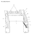
- FIG. 1 illustrates a conventional active headrest apparatus.
- right and left ends of a back plate 1 to which a pressure is applied by the upper body of a person who is seated in a car are combined to both end portions of a lower armature 2 as one body.
- An armature bracket 3 is securely combined to both end portions of the lower armature 2.
- Frame brackets 5 are securely combined to both side frames 4a that constitute a seat back frame 4, respectively.
- Link brackets 6 are rotatably combined to the armature bracket 3 and the frame bracket 5 via a hinge pin 7 and a pivot pin 8, respectively.
- the side frames 4a and the link brackets 6 are connected to each other via a spring member 9, and a pair of upper armatures 10 that are combined to the lower armature 2 as one body perforate a guide hole 4c formed in an upper frame 4b that connects the side frames 4a.
- a headrest stay 11 inserted in the upper armature 10 and fixed thereto is moved and rises, and a headrest 12 combined to the headrest stay 11 is moved and rises forward in a direction to the head of the person who is seated in the car and supports an occipital area of the person who is seated in the car, thereby performing a function of an active headrest.
- the frame bracket 5 combined to the side frames 4a protrudes toward an inside of the seat back frame 4.
- the seat back frame 4 interferes with the frame bracket 5.
- a contact area in which the upper body of the person who is seated in the car contacts the back plate 1 is decreased.
- a pressure applied to the back plate 1 is reduced.
- FIG. 2 illustrates another conventional active headrest apparatus.
- the active headrest apparatus includes a guide member 13 including guide grooves 13a respectively combined to insides of the side frames 4a, a back plate 1 in which guide pins 14 that are inserted in the guide grooves 13a and move along the guide grooves 13a are combined to right and left end portions of the back plate 1, respectively, and a spring member 9 that connects the side frames 4a and the back plate 1 to each other.
- the conventional problems described above may be overcome.
- the strength of the side frames 4a is greatly reduced, and due to the side frames 4a with the reduced strength, the overall strength of the seat back frame 4 is decreased, so that there is a possibility that another problem that the seat back frame 4 is easily destroyed due to shock caused by the rear-end collision and the safety of the person who is seated in the car is threatened, may occur.
- the present invention provides an active headrest apparatus for a vehicle seat having an improved structure in which a contact area in which the upper body of a person who is seated in a car in the event of a rear-end collision of the car is moved backward due to an inertial force and contacts a back plate is increased so that the function of an active headrest can be more stably and faithfully performed.
- the present invention also provides an active headrest apparatus for a vehicle seat having a function of a stopper in which a headrest that is moved and rises in a direction to the head of a person who is seated in a car in the event of a rear-end collision of the car can be constantly maintained in its original state so that neck injury of a person who is seated in a car can be more effectively prevented to the maximum.
- an active headrest apparatus for a vehicle seat including: a back plate connected to a lower armature and including slot holes formed in right and left ends of the back plate disposed in a direction to both side frames; combination pins perforating the slot holes and combined to the side frames so that the combination pins are movable along the slot holes; a back plate spring having one end combined to the side frames and the other end combined to the back plate and providing an elastic restoring force to the back plate; and an upper armature combined to the lower armature and having an upper end which perforates an upper frame.
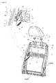
- FIG. 3 illustrates an active headrest apparatus according to an embodiment of the present invention
- FIG. 4 is a perspective view of a back plate of the active headrest apparatus illustrated in FIG. 3
- FIG. 5 illustrates a state before the active headrest apparatus of FIG. 3 operates
- FIGS. 6 and 7 illustrate a state after the active headrest apparatus of FIG. 3 operates.
- a vehicle seat includes a seat cushion that supports the lower body of a person who is seated in a car, a seat back that supports the upper body of the person who is seated in the car, and a headrest that is combined to a top end of the seat back so that the height of the headrest can be adjusted in a vertical direction, and that supports head and neck of the person who is seated in the car.
- the framework of the seat cushion is completed by a seat cushion frame, and the framework of the seat back is completed by a seat back frame 20 illustrated in FIG. 3 .
- the seat back frame 20 includes both side frames 21 disposed parallel to each other in right and left directions of a car body, and an upper frame 22 that connects top ends of the side frames 21 to each other.
- a pair of guide holes 22a are formed in the upper frame 22 in a vertical direction.
- the active headrest apparatus basically includes a back plate 30, a lower armature 40, combination pins 50, a back plate spring 60, and an upper armature 70, as illustrated in FIGS. 3 through 7 .
- the upper body of the person who is seated in the car is moved in a backward direction of the car due to an inertial force.
- the back plate 30 is pressurized by the upper body of the person who is seated in the car.
- Both ends of the lower armature 40 are connected to the back plate 30.
- the back plate 30 is connected to the side frames 21, respectively, while right and left ends of the back plate 30 are adjacent to the side frames 21.
- slot holes 34 are formed in right and left ends of the back plate 30, respectively.
- the back plate 30 includes a pressurizing portion 31 that is an intermediate portion to which a pressure is applied while the pressurizing portion 31 contacts the upper body of the person who is seated in the car in the event of a rear-end collision, an armature combination portion 32 that extends from the pressurizing portion 31 to both sides of the pressurizing portion 31 and is combined to the lower armature 40, and right and left both-end side portions 33 that extends from the armature combination portion 32 and is bent in such a way that the side portions 33 can be maintained adjacent to and parallel to the side frames 21 and the slot holes 34 are formed in the side portions 33, respectively.
- a pressurizing portion 31 that is an intermediate portion to which a pressure is applied while the pressurizing portion 31 contacts the upper body of the person who is seated in the car in the event of a rear-end collision
- an armature combination portion 32 that extends from the pressurizing portion 31 to both sides of the pressurizing portion 31 and is combined to the lower armature 40
- the combination pins 50 are used to connect right and left both ends of the back plate 30 to the side frames 21.
- the combination pins 50 perforate the slot holes 34 formed in the side portions 33 of the back plate 30 and then are combined to the side frames 21.
- the combination pins 50 are movable along the slot holes 34 so that, when the back plate 30 is moved forward and backward, the combination pins 50 are disposed in an opposite end portion to one end portion of the slot holes 34.
- the back plate spring 60 is a tensile spring. One end of the back plate spring 60 is combined to the side frames 21, and the other end thereof is combined to the back plate 30.
- the back plate spring 60 extends when the back plate 30 is moved backward and allows the back plate 30 that have been moved backward to be restored forward due to an elastic force.
- Two upper armatures 70 are provided. A bottom end of one of the upper armatures 70 is connected to the lower armature 40, and a top end thereof perforates the guide holes 22a formed in the upper frame 22.
- headrest stays 71 Bottom ends of headrest stays 71 are inserted in the upper armatures 70, respectively, in such way that the headrest stays 71 are securely installed via locking portions 73 and a headrest 75 is combined to top ends of the headrest stays 71 as one body.
- the slot holes 34 that are respectively formed in the side portions 33 of the back plate 30 and perforated by the combination pins 50 have a backward end that is higher than its forward end.
- the slot holes 34 have an inclination angle that is gradually increased from the forward end to the backward end.
- the inclination angle of the slot holes 34 is usually approximate to 45°, it may be changed at various angles according to the type of a seat.
- the slot holes 34 are not limited to a predetermined inclination angle.
- an elastic clip member 81 is disposed between the side frames 21 and the side portions 33 of the back plate 30 and is perforated by the combination pins 50.
- the elastic clip member 81 is formed of flexible plastics and thus, elastically supports the side portions 33 of the back plate 30 with respect to the side frames 21.
- the elastic clip member 81 absorbs an assembly tolerance of the side frames 21, the back plate 30, and the combination pins 50 and prevents the back plate 30 from being excessively inclined in a right or left direction, thereby preventing the back plate 30 from not smoothly operating in forward and backward directions.
- the combination pins 50 are disposed in front end portions (left end portions) of the slot holes 34, as illustrated in FIG. 6 .
- the upper armatures 70 perforate the guide holes 22a and protrude upward, as illustrated in FIG. 6 .
- the headrest 75 installed by combining the upper armatures 70 and the headrest stays 71 to one another is maintained to be inclined at about 5° in a direction to the person who is seated in the car, rises in a direction to the head of the person who is seated in the car, as illustrated in FIG. 6 and supports an occipital area of the person who is seated in the car, thereby faithfully performing the function of the active headrest.
- the headrest 75 that has risen When the occipital area of the person who is seated in the car contacts the headrest 75 that has risen, the headrest 75 is instantaneously strongly loaded. The headrest 75 that has risen is subject to be fallen again due to the load.
- the headrest 75 When the headrest 75 is moved downward and is restored to an initial position illustrated in FIG. 3 , the headrest 75 cannot support the occipital area of the person who is seated in the car. Thus, the head of the person who is seated in the car is leaned back, and the person who is seated in the car has a serious injury to his/her neck.
- the active headrest apparatus further includes a safety device that prevents the headrest 75 from being moved downward when the occipital area of the person who is seated in the car contacts the headrest 75 that has risen.
- the combination pins 50 before the upper body of the person who is seated in the car pressurizes the back plate 30 are disposed in rear end portions (right end portions) of the slot holes 34, as illustrated in FIG. 5 .
- the upper body of the person who is seated in the car pressurizes the back plate 30 as the inclined sides 35b of the stopper protrusions 35 smoothly cross the inclined sides 51 b of the pin protrusions 51, the back plate 30 starts being moved backward, and after the backward movement of the back plate 30 is completed, the combination pins 50 are disposed in front end portions (left end portions) of the slot holes 34, as illustrated in FIG. 7 .
- the headrest 75 rises in a direction to the head of the person who is seated in the car, as illustrated in FIG. 6 , and supports the occipital area of the person who is seated in the car.
- the headrest 75 supports the occipital portion of the person who is seated in the car, while being fixed to its original position.
- neck injury of the person who is seated in the car can be prevented to the maximum.
- An engagement force between the stopper protrusions 35 and the pin protrusions 51 should be greater than an elastic force of the back plate spring 60 so that the above-described operations can be smoothly performed.
- the present invention may use other type of a safety device than the stopper protrusions 35 and the pin protrusions 51.
- the active headrest apparatus may further include a locking cam 85 that is rotatably combined to the side portions 33 of the back plate 30 via a cam pin 83 and includes a pin confinement portion 85a disposed on one end of the locking cam 85, and a circular-arc-shaped cam spring 87 that has one end combined to the side portions 33 of the back plate 30 and the other end combined to the locking cam 85 and provides an elastic restoring force to the locking cam 85.
- a locking cam 85 that is rotatably combined to the side portions 33 of the back plate 30 via a cam pin 83 and includes a pin confinement portion 85a disposed on one end of the locking cam 85, and a circular-arc-shaped cam spring 87 that has one end combined to the side portions 33 of the back plate 30 and the other end combined to the locking cam 85 and provides an elastic restoring force to the locking cam 85.
- the pin confinement portion 85a has a circular-arc-shape in which its cross-section is hook-shaped and its outer circumferential surface is curved.
- the pin confinement portion 85a of the locking cam 85 before the upper body of the person who is seated in the car pressurizes the back plate 30 is maintained to overlap with the slot holes 34 so as to cover a portion of the front end (left end) portions of the slot holes 34, as illustrated in FIG. 5 .
- the locking cam 85 is maintained in a contact state with the combination pins 50 and is rotated around the cam pin 83 counterclockwise in the state of FIG. 5 (in this case, the cam spring 87 is in a tensile state).
- the back plate 30 can be continuously moved backward (i.e., the combination pins 50 can be continuously moved to the front end portions of the slot holes 34).
- the combination pins 50 after the backward movement of the back plate 30 is completed, are disposed in the front end portions (left end portions) of the slot holes 34, as illustrated in FIG. 7 .
- the locking cam 85 that has been rotated around the cam pin 83 counterclockwise is rotated clockwise due to the restoring force of the cam spring 87 and is restored to its initial state.
- the combination pins 50 disposed in the front end portions (left end portions) of the slot holes 34 are confined by the pin confinement portion 85a.
- the elastic force of the cam spring 87 should be greater than the elastic force of the back plate spring 60 so that the above-described operations can be smoothly performed.
- the structure of the safety device including the stopper protrusions 35 and the pin protrusions 51 and the structure of the safety device including the locking cam 85 and the cam spring 87 may be separately or together used.
- the two structures may be used together in order to maximize the performance of the safety device.
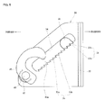
- the present invention may use a structure formed as one body by modulating the back plate 30 and the lower armature 40, as illustrated in FIG. 8 .
- the lower armature 50 is formed as one body with the back plate 30 along edges of the back plate 30, so that costs can be reduced, operations can be conveniently performed and productivity can be improved.
- a component such as the frame bracket 5 or the guide member 13 that interferes with the upper body of the person who is seated in the car when the upper body of the person who is seated in the car is moved backward due to the inertia force in the event of the rear-end collision, is not combined to the side frames 21, like in the conventional art described with reference to FIGS. 1 and 2 , so that a contact area in which the person who is seated in the car contacts the back plate 30 can be greatly increased.
- the pressure applied to the back plate 30 can be increased, and a distance at which the back plate 1 is moved backward can be increased.
- a distance at which the headrest 75 rises forward in a direction to the head of the person who is seated in the car can be increased so that the function of the active headrest can be more faithfully performed.
- the present invention does not use the component, such as the frame bracket 5 or the guide member 13 used in the conventional art, so that the number of components can be reduced and costs can be reduced.
- an active headrest apparatus As described above, in an active headrest apparatus according to the present invention, a contact area in which the upper body of a person who is seated in a car in the event of a rear-end collision of the car is moved backward due to an inertial force and contacts a back plate can be increased, and a distance at which a headrest is moved and rises can be increased so that the function of an active headrest can be more faithfully performed and neck injury of the person who is seated in the car can be prevented to the maximum.
Landscapes
- Engineering & Computer Science (AREA)
- Aviation & Aerospace Engineering (AREA)
- Transportation (AREA)
- Mechanical Engineering (AREA)
- Seats For Vehicles (AREA)
- Chair Legs, Seat Parts, And Backrests (AREA)
Applications Claiming Priority (1)
| Application Number | Priority Date | Filing Date | Title |
|---|---|---|---|
| KR1020090050770A KR101073958B1 (ko) | 2009-06-09 | 2009-06-09 | 차량 시트용 액티브 헤드레스트 장치 |
Publications (3)
| Publication Number | Publication Date |
|---|---|
| EP2261079A2 true EP2261079A2 (fr) | 2010-12-15 |
| EP2261079A3 EP2261079A3 (fr) | 2012-03-21 |
| EP2261079B1 EP2261079B1 (fr) | 2016-11-30 |
Family
ID=42344793
Family Applications (1)
| Application Number | Title | Priority Date | Filing Date |
|---|---|---|---|
| EP10164560.4A Active EP2261079B1 (fr) | 2009-06-09 | 2010-06-01 | Dispositif d'appui-tête actif pour siège de véhicule |
Country Status (4)
| Country | Link |
|---|---|
| US (1) | US8371648B2 (fr) |
| EP (1) | EP2261079B1 (fr) |
| KR (1) | KR101073958B1 (fr) |
| CN (1) | CN101954876B (fr) |
Cited By (1)
| Publication number | Priority date | Publication date | Assignee | Title |
|---|---|---|---|---|
| CN103192749A (zh) * | 2013-04-21 | 2013-07-10 | 山东科技大学 | 一种汽车座椅主动头枕装置 |
Families Citing this family (20)
| Publication number | Priority date | Publication date | Assignee | Title |
|---|---|---|---|---|
| KR101278646B1 (ko) * | 2011-09-02 | 2013-06-25 | 교통안전공단 | 모의 추돌 시스템 |
| CN102745111B (zh) * | 2012-06-30 | 2015-08-26 | 长城汽车股份有限公司 | 汽车座椅主动式头枕装置 |
| US20150352982A1 (en) * | 2012-12-28 | 2015-12-10 | Ts Tech Co., Ltd. | Seat device |
| CN103129429A (zh) * | 2013-03-19 | 2013-06-05 | 江苏大学 | 机动车安全座椅 |
| JP6075196B2 (ja) * | 2013-05-10 | 2017-02-08 | トヨタ紡織株式会社 | 乗り物用シート |
| US9789794B1 (en) | 2016-07-19 | 2017-10-17 | Ford Global Technologies, Llc | Active head restraint |
| CN106427713A (zh) * | 2016-09-08 | 2017-02-22 | 广州汽车集团零部件有限公司 | 一种结构简单且轻量化高强度的汽车座椅骨架及座椅 |
| CN106427712A (zh) * | 2016-09-08 | 2017-02-22 | 广州汽车集团零部件有限公司 | 一种八向汽车电动座椅骨架及座椅 |
| US10166900B2 (en) | 2017-02-09 | 2019-01-01 | Ford Global Technologies, Llc | Internal upper seatback support for driving and sleeper seats |
| US10569674B2 (en) | 2017-03-02 | 2020-02-25 | Ford Global Technologies, Llc | Mechanism for a supine motor vehicle seating assembly |
| US10065535B1 (en) * | 2017-03-02 | 2018-09-04 | Ford Global Technologies, Llc | Seatback lift mechanism for a supine motor vehicle seating assembly |
| US10434905B2 (en) | 2017-03-02 | 2019-10-08 | Ford Global Technologies, Llc | Collapsible lift mechanism for H-point lift |
| US10166887B2 (en) | 2017-03-02 | 2019-01-01 | Ford Global Technologies, Llc | Seatback lift mechanism for a supine motor vehicle seating assembly |
| US10081270B1 (en) | 2017-03-03 | 2018-09-25 | Ford Global Technologies, Llc | Front seat sleeper seat and features |
| US10525861B2 (en) | 2017-03-22 | 2020-01-07 | Ford Global Technologies, Llc | Leg support options for sleeper seats |
| KR102361529B1 (ko) | 2017-09-28 | 2022-02-11 | 주식회사 다스 | 관성 액티브 헤드레스트 |
| US10632873B2 (en) | 2018-04-04 | 2020-04-28 | Ford Global Technologies, Llc | Seat structure dual motion recliner pivot mechanism |
| KR102107413B1 (ko) | 2018-10-29 | 2020-05-07 | 주식회사 서연이화 | 가변형 차량용 시트 |
| US11007908B2 (en) | 2019-06-25 | 2021-05-18 | Ford Global Technologies, Llc | Upper thoracic support paddle attachment assembly |
| FR3119805B1 (fr) * | 2021-02-18 | 2023-02-24 | Faurecia Sieges Dautomobile | Siège de véhicule |
Family Cites Families (10)
| Publication number | Priority date | Publication date | Assignee | Title |
|---|---|---|---|---|
| DE10047406A1 (de) * | 2000-09-26 | 2002-04-11 | Daimler Chrysler Ag | Kopfstütze |
| FR2830219B1 (fr) * | 2001-10-01 | 2003-12-05 | Faurecia Sieges Automobile | Siege de vehicule dote d'un dispositif de securite mobile |
| US7097242B2 (en) * | 2003-02-06 | 2006-08-29 | Lear Corporation | Anti-backdriving active head restraint |
| DE10313800A1 (de) * | 2003-03-20 | 2004-09-30 | Brose Fahrzeugteile Gmbh & Co. Kommanditgesellschaft, Coburg | Kopfstützenanordnung für einen Kraftfahrzeugsitz |
| US6779840B1 (en) | 2003-08-27 | 2004-08-24 | Lear Corporation | Locking and unlocking mechanism for an active headrest for a vehicle seat |
| KR100794046B1 (ko) * | 2006-08-10 | 2008-01-10 | 현대자동차주식회사 | 액티브 헤드 레스트의 로킹 구조 |
| KR100837910B1 (ko) * | 2006-12-05 | 2008-06-13 | 현대자동차주식회사 | 액티브 헤드 레스트의 높이 유지 장치 |
| US7374239B1 (en) * | 2007-01-16 | 2008-05-20 | Ford Global Technologies, Inc. | Active head restraint with self resetting mechanism |
| JP5076830B2 (ja) * | 2007-11-21 | 2012-11-21 | トヨタ紡織株式会社 | クラッチ機構 |
| US20090167066A1 (en) * | 2007-12-26 | 2009-07-02 | Aisin Seiki Kabushiki Kaisha | Seat apparatus for vehicle |
-
2009
- 2009-06-09 KR KR1020090050770A patent/KR101073958B1/ko active Active
-
2010
- 2010-06-01 EP EP10164560.4A patent/EP2261079B1/fr active Active
- 2010-06-03 US US12/793,259 patent/US8371648B2/en active Active
- 2010-06-08 CN CN2010101947585A patent/CN101954876B/zh active Active
Non-Patent Citations (1)
| Title |
|---|
| None |
Cited By (2)
| Publication number | Priority date | Publication date | Assignee | Title |
|---|---|---|---|---|
| CN103192749A (zh) * | 2013-04-21 | 2013-07-10 | 山东科技大学 | 一种汽车座椅主动头枕装置 |
| CN103192749B (zh) * | 2013-04-21 | 2015-07-15 | 山东科技大学 | 一种汽车座椅主动头枕装置 |
Also Published As
| Publication number | Publication date |
|---|---|
| KR20100132121A (ko) | 2010-12-17 |
| US20100308629A1 (en) | 2010-12-09 |
| KR101073958B1 (ko) | 2011-10-17 |
| US8371648B2 (en) | 2013-02-12 |
| EP2261079A3 (fr) | 2012-03-21 |
| CN101954876A (zh) | 2011-01-26 |
| EP2261079B1 (fr) | 2016-11-30 |
| CN101954876B (zh) | 2013-05-01 |
Similar Documents
| Publication | Publication Date | Title |
|---|---|---|
| US8371648B2 (en) | Active headrest apparatus for vehicle seat | |
| CN103003100B (zh) | 乘坐物用座椅 | |
| CN102897071B (zh) | 座椅靠背框架 | |
| US8632126B2 (en) | Vehicle seat | |
| CN104781105B (zh) | 车用座椅 | |
| CN103025574A (zh) | 乘坐物用座椅 | |
| EP2492158B1 (fr) | Ensemble de ceinture de sécurité | |
| EP2894060B1 (fr) | Siège de véhicule | |
| JP3619855B2 (ja) | 自動車のサブマリン防止用パネル構造 | |
| JP4728670B2 (ja) | 自動車用シートのバックレストフレーム | |
| JP3770452B2 (ja) | 車両用シート装置 | |
| JP5808168B2 (ja) | 車両用シート | |
| JP2009051480A (ja) | 車両用シートのシートバック構造 | |
| JP5813394B2 (ja) | 車両用シート | |
| JP5883422B2 (ja) | 乗物用シート | |
| JP2012056455A (ja) | 車両用シート | |
| JP6049832B2 (ja) | 車両用シート | |
| KR20150063697A (ko) | 차량시트의 후방추돌 충격완화 장치 | |
| JP5252936B2 (ja) | 車両用シート | |
| KR101850730B1 (ko) | 차량용 헤드레스트 | |
| JP2013049386A (ja) | 車両用シート | |
| JP6466535B2 (ja) | 乗物用シート | |
| CN107960067A (zh) | 乘坐物用座椅 | |
| JP5823173B2 (ja) | 車両用シート | |
| JP2012166725A (ja) | 車両用シート |
Legal Events
| Date | Code | Title | Description |
|---|---|---|---|
| PUAI | Public reference made under article 153(3) epc to a published international application that has entered the european phase |
Free format text: ORIGINAL CODE: 0009012 |
|
| AK | Designated contracting states |
Kind code of ref document: A2 Designated state(s): AL AT BE BG CH CY CZ DE DK EE ES FI FR GB GR HR HU IE IS IT LI LT LU LV MC MK MT NL NO PL PT RO SE SI SK SM TR |
|
| AX | Request for extension of the european patent |
Extension state: BA ME RS |
|
| PUAL | Search report despatched |
Free format text: ORIGINAL CODE: 0009013 |
|
| AK | Designated contracting states |
Kind code of ref document: A3 Designated state(s): AL AT BE BG CH CY CZ DE DK EE ES FI FR GB GR HR HU IE IS IT LI LT LU LV MC MK MT NL NO PL PT RO SE SI SK SM TR |
|
| AX | Request for extension of the european patent |
Extension state: BA ME RS |
|
| RIC1 | Information provided on ipc code assigned before grant |
Ipc: B60N 2/48 20060101AFI20120216BHEP |
|
| 17P | Request for examination filed |
Effective date: 20120914 |
|
| 17Q | First examination report despatched |
Effective date: 20151001 |
|
| GRAP | Despatch of communication of intention to grant a patent |
Free format text: ORIGINAL CODE: EPIDOSNIGR1 |
|
| INTG | Intention to grant announced |
Effective date: 20160704 |
|
| RIN1 | Information on inventor provided before grant (corrected) |
Inventor name: KIM, DO-HYUNG Inventor name: PARK, SANG-NAM Inventor name: LEE, JONG-YOON Inventor name: NAM, JIN-YOUNG Inventor name: LEE, IN-HO |
|
| GRAS | Grant fee paid |
Free format text: ORIGINAL CODE: EPIDOSNIGR3 |
|
| GRAA | (expected) grant |
Free format text: ORIGINAL CODE: 0009210 |
|
| AK | Designated contracting states |
Kind code of ref document: B1 Designated state(s): AL AT BE BG CH CY CZ DE DK EE ES FI FR GB GR HR HU IE IS IT LI LT LU LV MC MK MT NL NO PL PT RO SE SI SK SM TR |
|
| REG | Reference to a national code |
Ref country code: CH Ref legal event code: EP Ref country code: GB Ref legal event code: FG4D |
|
| REG | Reference to a national code |
Ref country code: AT Ref legal event code: REF Ref document number: 849463 Country of ref document: AT Kind code of ref document: T Effective date: 20161215 |
|
| REG | Reference to a national code |
Ref country code: IE Ref legal event code: FG4D |
|
| REG | Reference to a national code |
Ref country code: DE Ref legal event code: R096 Ref document number: 602010038377 Country of ref document: DE |
|
| PG25 | Lapsed in a contracting state [announced via postgrant information from national office to epo] |
Ref country code: LV Free format text: LAPSE BECAUSE OF FAILURE TO SUBMIT A TRANSLATION OF THE DESCRIPTION OR TO PAY THE FEE WITHIN THE PRESCRIBED TIME-LIMIT Effective date: 20161130 |
|
| REG | Reference to a national code |
Ref country code: LT Ref legal event code: MG4D |
|
| REG | Reference to a national code |
Ref country code: NL Ref legal event code: MP Effective date: 20161130 |
|
| REG | Reference to a national code |
Ref country code: AT Ref legal event code: MK05 Ref document number: 849463 Country of ref document: AT Kind code of ref document: T Effective date: 20161130 |
|
| PG25 | Lapsed in a contracting state [announced via postgrant information from national office to epo] |
Ref country code: SE Free format text: LAPSE BECAUSE OF FAILURE TO SUBMIT A TRANSLATION OF THE DESCRIPTION OR TO PAY THE FEE WITHIN THE PRESCRIBED TIME-LIMIT Effective date: 20161130 Ref country code: GR Free format text: LAPSE BECAUSE OF FAILURE TO SUBMIT A TRANSLATION OF THE DESCRIPTION OR TO PAY THE FEE WITHIN THE PRESCRIBED TIME-LIMIT Effective date: 20170301 Ref country code: LT Free format text: LAPSE BECAUSE OF FAILURE TO SUBMIT A TRANSLATION OF THE DESCRIPTION OR TO PAY THE FEE WITHIN THE PRESCRIBED TIME-LIMIT Effective date: 20161130 Ref country code: NO Free format text: LAPSE BECAUSE OF FAILURE TO SUBMIT A TRANSLATION OF THE DESCRIPTION OR TO PAY THE FEE WITHIN THE PRESCRIBED TIME-LIMIT Effective date: 20170228 |
|
| PG25 | Lapsed in a contracting state [announced via postgrant information from national office to epo] |
Ref country code: FI Free format text: LAPSE BECAUSE OF FAILURE TO SUBMIT A TRANSLATION OF THE DESCRIPTION OR TO PAY THE FEE WITHIN THE PRESCRIBED TIME-LIMIT Effective date: 20161130 Ref country code: PL Free format text: LAPSE BECAUSE OF FAILURE TO SUBMIT A TRANSLATION OF THE DESCRIPTION OR TO PAY THE FEE WITHIN THE PRESCRIBED TIME-LIMIT Effective date: 20161130 Ref country code: ES Free format text: LAPSE BECAUSE OF FAILURE TO SUBMIT A TRANSLATION OF THE DESCRIPTION OR TO PAY THE FEE WITHIN THE PRESCRIBED TIME-LIMIT Effective date: 20161130 Ref country code: PT Free format text: LAPSE BECAUSE OF FAILURE TO SUBMIT A TRANSLATION OF THE DESCRIPTION OR TO PAY THE FEE WITHIN THE PRESCRIBED TIME-LIMIT Effective date: 20170330 Ref country code: HR Free format text: LAPSE BECAUSE OF FAILURE TO SUBMIT A TRANSLATION OF THE DESCRIPTION OR TO PAY THE FEE WITHIN THE PRESCRIBED TIME-LIMIT Effective date: 20161130 Ref country code: AT Free format text: LAPSE BECAUSE OF FAILURE TO SUBMIT A TRANSLATION OF THE DESCRIPTION OR TO PAY THE FEE WITHIN THE PRESCRIBED TIME-LIMIT Effective date: 20161130 |
|
| PG25 | Lapsed in a contracting state [announced via postgrant information from national office to epo] |
Ref country code: NL Free format text: LAPSE BECAUSE OF FAILURE TO SUBMIT A TRANSLATION OF THE DESCRIPTION OR TO PAY THE FEE WITHIN THE PRESCRIBED TIME-LIMIT Effective date: 20161130 |
|
| PG25 | Lapsed in a contracting state [announced via postgrant information from national office to epo] |
Ref country code: EE Free format text: LAPSE BECAUSE OF FAILURE TO SUBMIT A TRANSLATION OF THE DESCRIPTION OR TO PAY THE FEE WITHIN THE PRESCRIBED TIME-LIMIT Effective date: 20161130 Ref country code: CZ Free format text: LAPSE BECAUSE OF FAILURE TO SUBMIT A TRANSLATION OF THE DESCRIPTION OR TO PAY THE FEE WITHIN THE PRESCRIBED TIME-LIMIT Effective date: 20161130 Ref country code: SK Free format text: LAPSE BECAUSE OF FAILURE TO SUBMIT A TRANSLATION OF THE DESCRIPTION OR TO PAY THE FEE WITHIN THE PRESCRIBED TIME-LIMIT Effective date: 20161130 Ref country code: RO Free format text: LAPSE BECAUSE OF FAILURE TO SUBMIT A TRANSLATION OF THE DESCRIPTION OR TO PAY THE FEE WITHIN THE PRESCRIBED TIME-LIMIT Effective date: 20161130 Ref country code: DK Free format text: LAPSE BECAUSE OF FAILURE TO SUBMIT A TRANSLATION OF THE DESCRIPTION OR TO PAY THE FEE WITHIN THE PRESCRIBED TIME-LIMIT Effective date: 20161130 |
|
| PG25 | Lapsed in a contracting state [announced via postgrant information from national office to epo] |
Ref country code: IT Free format text: LAPSE BECAUSE OF FAILURE TO SUBMIT A TRANSLATION OF THE DESCRIPTION OR TO PAY THE FEE WITHIN THE PRESCRIBED TIME-LIMIT Effective date: 20161130 Ref country code: SM Free format text: LAPSE BECAUSE OF FAILURE TO SUBMIT A TRANSLATION OF THE DESCRIPTION OR TO PAY THE FEE WITHIN THE PRESCRIBED TIME-LIMIT Effective date: 20161130 Ref country code: BG Free format text: LAPSE BECAUSE OF FAILURE TO SUBMIT A TRANSLATION OF THE DESCRIPTION OR TO PAY THE FEE WITHIN THE PRESCRIBED TIME-LIMIT Effective date: 20170228 Ref country code: BE Free format text: LAPSE BECAUSE OF FAILURE TO SUBMIT A TRANSLATION OF THE DESCRIPTION OR TO PAY THE FEE WITHIN THE PRESCRIBED TIME-LIMIT Effective date: 20161130 |
|
| REG | Reference to a national code |
Ref country code: DE Ref legal event code: R097 Ref document number: 602010038377 Country of ref document: DE |
|
| PLBE | No opposition filed within time limit |
Free format text: ORIGINAL CODE: 0009261 |
|
| STAA | Information on the status of an ep patent application or granted ep patent |
Free format text: STATUS: NO OPPOSITION FILED WITHIN TIME LIMIT |
|
| 26N | No opposition filed |
Effective date: 20170831 |
|
| REG | Reference to a national code |
Ref country code: DE Ref legal event code: R079 Ref document number: 602010038377 Country of ref document: DE Free format text: PREVIOUS MAIN CLASS: B60N0002480000 Ipc: B60N0002800000 |
|
| PG25 | Lapsed in a contracting state [announced via postgrant information from national office to epo] |
Ref country code: SI Free format text: LAPSE BECAUSE OF FAILURE TO SUBMIT A TRANSLATION OF THE DESCRIPTION OR TO PAY THE FEE WITHIN THE PRESCRIBED TIME-LIMIT Effective date: 20161130 |
|
| PG25 | Lapsed in a contracting state [announced via postgrant information from national office to epo] |
Ref country code: MC Free format text: LAPSE BECAUSE OF FAILURE TO SUBMIT A TRANSLATION OF THE DESCRIPTION OR TO PAY THE FEE WITHIN THE PRESCRIBED TIME-LIMIT Effective date: 20161130 |
|
| REG | Reference to a national code |
Ref country code: CH Ref legal event code: PL |
|
| GBPC | Gb: european patent ceased through non-payment of renewal fee |
Effective date: 20170601 |
|
| REG | Reference to a national code |
Ref country code: IE Ref legal event code: MM4A |
|
| REG | Reference to a national code |
Ref country code: FR Ref legal event code: ST Effective date: 20180228 |
|
| PG25 | Lapsed in a contracting state [announced via postgrant information from national office to epo] |
Ref country code: LI Free format text: LAPSE BECAUSE OF NON-PAYMENT OF DUE FEES Effective date: 20170630 Ref country code: LU Free format text: LAPSE BECAUSE OF NON-PAYMENT OF DUE FEES Effective date: 20170601 Ref country code: CH Free format text: LAPSE BECAUSE OF NON-PAYMENT OF DUE FEES Effective date: 20170630 Ref country code: GB Free format text: LAPSE BECAUSE OF NON-PAYMENT OF DUE FEES Effective date: 20170601 Ref country code: IE Free format text: LAPSE BECAUSE OF NON-PAYMENT OF DUE FEES Effective date: 20170601 |
|
| PG25 | Lapsed in a contracting state [announced via postgrant information from national office to epo] |
Ref country code: FR Free format text: LAPSE BECAUSE OF NON-PAYMENT OF DUE FEES Effective date: 20170630 |
|
| PG25 | Lapsed in a contracting state [announced via postgrant information from national office to epo] |
Ref country code: MT Free format text: LAPSE BECAUSE OF NON-PAYMENT OF DUE FEES Effective date: 20170601 |
|
| PG25 | Lapsed in a contracting state [announced via postgrant information from national office to epo] |
Ref country code: HU Free format text: LAPSE BECAUSE OF FAILURE TO SUBMIT A TRANSLATION OF THE DESCRIPTION OR TO PAY THE FEE WITHIN THE PRESCRIBED TIME-LIMIT; INVALID AB INITIO Effective date: 20100601 |
|
| PG25 | Lapsed in a contracting state [announced via postgrant information from national office to epo] |
Ref country code: CY Free format text: LAPSE BECAUSE OF NON-PAYMENT OF DUE FEES Effective date: 20161130 |
|
| PG25 | Lapsed in a contracting state [announced via postgrant information from national office to epo] |
Ref country code: MK Free format text: LAPSE BECAUSE OF FAILURE TO SUBMIT A TRANSLATION OF THE DESCRIPTION OR TO PAY THE FEE WITHIN THE PRESCRIBED TIME-LIMIT Effective date: 20161130 |
|
| PG25 | Lapsed in a contracting state [announced via postgrant information from national office to epo] |
Ref country code: TR Free format text: LAPSE BECAUSE OF FAILURE TO SUBMIT A TRANSLATION OF THE DESCRIPTION OR TO PAY THE FEE WITHIN THE PRESCRIBED TIME-LIMIT Effective date: 20161130 |
|
| PG25 | Lapsed in a contracting state [announced via postgrant information from national office to epo] |
Ref country code: AL Free format text: LAPSE BECAUSE OF FAILURE TO SUBMIT A TRANSLATION OF THE DESCRIPTION OR TO PAY THE FEE WITHIN THE PRESCRIBED TIME-LIMIT Effective date: 20161130 Ref country code: IS Free format text: LAPSE BECAUSE OF FAILURE TO SUBMIT A TRANSLATION OF THE DESCRIPTION OR TO PAY THE FEE WITHIN THE PRESCRIBED TIME-LIMIT Effective date: 20170330 |
|
| PGFP | Annual fee paid to national office [announced via postgrant information from national office to epo] |
Ref country code: DE Payment date: 20250520 Year of fee payment: 16 |