EP2261501A2 - Méthode et dispositif de montage d'une pale de rotor pour une éolienne - Google Patents
Méthode et dispositif de montage d'une pale de rotor pour une éolienne Download PDFInfo
- Publication number
- EP2261501A2 EP2261501A2 EP10005443A EP10005443A EP2261501A2 EP 2261501 A2 EP2261501 A2 EP 2261501A2 EP 10005443 A EP10005443 A EP 10005443A EP 10005443 A EP10005443 A EP 10005443A EP 2261501 A2 EP2261501 A2 EP 2261501A2
- Authority
- EP
- European Patent Office
- Prior art keywords
- shell
- web
- holding device
- movement
- webs
- Prior art date
- Legal status (The legal status is an assumption and is not a legal conclusion. Google has not performed a legal analysis and makes no representation as to the accuracy of the status listed.)
- Granted
Links
- 238000000034 method Methods 0.000 title claims abstract description 24
- 239000000853 adhesive Substances 0.000 claims abstract description 39
- 230000001070 adhesive effect Effects 0.000 claims abstract description 39
- 238000004519 manufacturing process Methods 0.000 description 4
- 239000011347 resin Substances 0.000 description 3
- 229920005989 resin Polymers 0.000 description 3
- 230000037303 wrinkles Effects 0.000 description 3
- 238000004026 adhesive bonding Methods 0.000 description 2
- 238000009434 installation Methods 0.000 description 2
- 230000003993 interaction Effects 0.000 description 2
- 230000014759 maintenance of location Effects 0.000 description 2
- 238000012805 post-processing Methods 0.000 description 2
- 239000000969 carrier Substances 0.000 description 1
- 230000006866 deterioration Effects 0.000 description 1
- 230000000694 effects Effects 0.000 description 1
- 239000004744 fabric Substances 0.000 description 1
- 239000011152 fibreglass Substances 0.000 description 1
- 239000011521 glass Substances 0.000 description 1
- 239000003365 glass fiber Substances 0.000 description 1
- 238000003384 imaging method Methods 0.000 description 1
- 238000001802 infusion Methods 0.000 description 1
- 238000002347 injection Methods 0.000 description 1
- 239000007924 injection Substances 0.000 description 1
- 239000007788 liquid Substances 0.000 description 1
- 239000000203 mixture Substances 0.000 description 1
- 230000000284 resting effect Effects 0.000 description 1
- 230000000452 restraining effect Effects 0.000 description 1
- 239000000126 substance Substances 0.000 description 1
- 238000009736 wetting Methods 0.000 description 1
Images
Classifications
-
- F—MECHANICAL ENGINEERING; LIGHTING; HEATING; WEAPONS; BLASTING
- F03—MACHINES OR ENGINES FOR LIQUIDS; WIND, SPRING, OR WEIGHT MOTORS; PRODUCING MECHANICAL POWER OR A REACTIVE PROPULSIVE THRUST, NOT OTHERWISE PROVIDED FOR
- F03D—WIND MOTORS
- F03D1/00—Wind motors with rotation axis substantially parallel to the air flow entering the rotor
- F03D1/06—Rotors
- F03D1/065—Rotors characterised by their construction elements
- F03D1/0675—Rotors characterised by their construction elements of the blades
-
- B—PERFORMING OPERATIONS; TRANSPORTING
- B29—WORKING OF PLASTICS; WORKING OF SUBSTANCES IN A PLASTIC STATE IN GENERAL
- B29D—PRODUCING PARTICULAR ARTICLES FROM PLASTICS OR FROM SUBSTANCES IN A PLASTIC STATE
- B29D99/00—Subject matter not provided for in other groups of this subclass
- B29D99/0025—Producing blades or the like, e.g. blades for turbines, propellers, or wings
- B29D99/0028—Producing blades or the like, e.g. blades for turbines, propellers, or wings hollow blades
-
- B—PERFORMING OPERATIONS; TRANSPORTING
- B29—WORKING OF PLASTICS; WORKING OF SUBSTANCES IN A PLASTIC STATE IN GENERAL
- B29C—SHAPING OR JOINING OF PLASTICS; SHAPING OF MATERIAL IN A PLASTIC STATE, NOT OTHERWISE PROVIDED FOR; AFTER-TREATMENT OF THE SHAPED PRODUCTS, e.g. REPAIRING
- B29C65/00—Joining or sealing of preformed parts, e.g. welding of plastics materials; Apparatus therefor
- B29C65/48—Joining or sealing of preformed parts, e.g. welding of plastics materials; Apparatus therefor using adhesives, i.e. using supplementary joining material; solvent bonding
-
- B—PERFORMING OPERATIONS; TRANSPORTING
- B29—WORKING OF PLASTICS; WORKING OF SUBSTANCES IN A PLASTIC STATE IN GENERAL
- B29C—SHAPING OR JOINING OF PLASTICS; SHAPING OF MATERIAL IN A PLASTIC STATE, NOT OTHERWISE PROVIDED FOR; AFTER-TREATMENT OF THE SHAPED PRODUCTS, e.g. REPAIRING
- B29C65/00—Joining or sealing of preformed parts, e.g. welding of plastics materials; Apparatus therefor
- B29C65/48—Joining or sealing of preformed parts, e.g. welding of plastics materials; Apparatus therefor using adhesives, i.e. using supplementary joining material; solvent bonding
- B29C65/4805—Joining or sealing of preformed parts, e.g. welding of plastics materials; Apparatus therefor using adhesives, i.e. using supplementary joining material; solvent bonding characterised by the type of adhesives
- B29C65/483—Reactive adhesives, e.g. chemically curing adhesives
-
- B—PERFORMING OPERATIONS; TRANSPORTING
- B29—WORKING OF PLASTICS; WORKING OF SUBSTANCES IN A PLASTIC STATE IN GENERAL
- B29C—SHAPING OR JOINING OF PLASTICS; SHAPING OF MATERIAL IN A PLASTIC STATE, NOT OTHERWISE PROVIDED FOR; AFTER-TREATMENT OF THE SHAPED PRODUCTS, e.g. REPAIRING
- B29C65/00—Joining or sealing of preformed parts, e.g. welding of plastics materials; Apparatus therefor
- B29C65/78—Means for handling the parts to be joined, e.g. for making containers or hollow articles, e.g. means for handling sheets, plates, web-like materials, tubular articles, hollow articles or elements to be joined therewith; Means for discharging the joined articles from the joining apparatus
- B29C65/7841—Holding or clamping means for handling purposes
-
- B—PERFORMING OPERATIONS; TRANSPORTING
- B29—WORKING OF PLASTICS; WORKING OF SUBSTANCES IN A PLASTIC STATE IN GENERAL
- B29C—SHAPING OR JOINING OF PLASTICS; SHAPING OF MATERIAL IN A PLASTIC STATE, NOT OTHERWISE PROVIDED FOR; AFTER-TREATMENT OF THE SHAPED PRODUCTS, e.g. REPAIRING
- B29C66/00—General aspects of processes or apparatus for joining preformed parts
- B29C66/01—General aspects dealing with the joint area or with the area to be joined
- B29C66/05—Particular design of joint configurations
- B29C66/301—Three-dimensional joints, i.e. the joined area being substantially non-flat
-
- B—PERFORMING OPERATIONS; TRANSPORTING
- B29—WORKING OF PLASTICS; WORKING OF SUBSTANCES IN A PLASTIC STATE IN GENERAL
- B29C—SHAPING OR JOINING OF PLASTICS; SHAPING OF MATERIAL IN A PLASTIC STATE, NOT OTHERWISE PROVIDED FOR; AFTER-TREATMENT OF THE SHAPED PRODUCTS, e.g. REPAIRING
- B29C66/00—General aspects of processes or apparatus for joining preformed parts
- B29C66/50—General aspects of joining tubular articles; General aspects of joining long products, i.e. bars or profiled elements; General aspects of joining single elements to tubular articles, hollow articles or bars; General aspects of joining several hollow-preforms to form hollow or tubular articles
- B29C66/51—Joining tubular articles, profiled elements or bars; Joining single elements to tubular articles, hollow articles or bars; Joining several hollow-preforms to form hollow or tubular articles
- B29C66/52—Joining tubular articles, bars or profiled elements
- B29C66/524—Joining profiled elements
-
- B—PERFORMING OPERATIONS; TRANSPORTING
- B29—WORKING OF PLASTICS; WORKING OF SUBSTANCES IN A PLASTIC STATE IN GENERAL
- B29C—SHAPING OR JOINING OF PLASTICS; SHAPING OF MATERIAL IN A PLASTIC STATE, NOT OTHERWISE PROVIDED FOR; AFTER-TREATMENT OF THE SHAPED PRODUCTS, e.g. REPAIRING
- B29C66/00—General aspects of processes or apparatus for joining preformed parts
- B29C66/50—General aspects of joining tubular articles; General aspects of joining long products, i.e. bars or profiled elements; General aspects of joining single elements to tubular articles, hollow articles or bars; General aspects of joining several hollow-preforms to form hollow or tubular articles
- B29C66/51—Joining tubular articles, profiled elements or bars; Joining single elements to tubular articles, hollow articles or bars; Joining several hollow-preforms to form hollow or tubular articles
- B29C66/53—Joining single elements to tubular articles, hollow articles or bars
- B29C66/532—Joining single elements to the wall of tubular articles, hollow articles or bars
-
- B—PERFORMING OPERATIONS; TRANSPORTING
- B29—WORKING OF PLASTICS; WORKING OF SUBSTANCES IN A PLASTIC STATE IN GENERAL
- B29C—SHAPING OR JOINING OF PLASTICS; SHAPING OF MATERIAL IN A PLASTIC STATE, NOT OTHERWISE PROVIDED FOR; AFTER-TREATMENT OF THE SHAPED PRODUCTS, e.g. REPAIRING
- B29C66/00—General aspects of processes or apparatus for joining preformed parts
- B29C66/50—General aspects of joining tubular articles; General aspects of joining long products, i.e. bars or profiled elements; General aspects of joining single elements to tubular articles, hollow articles or bars; General aspects of joining several hollow-preforms to form hollow or tubular articles
- B29C66/51—Joining tubular articles, profiled elements or bars; Joining single elements to tubular articles, hollow articles or bars; Joining several hollow-preforms to form hollow or tubular articles
- B29C66/54—Joining several hollow-preforms, e.g. half-shells, to form hollow articles, e.g. for making balls, containers; Joining several hollow-preforms, e.g. half-cylinders, to form tubular articles
-
- B—PERFORMING OPERATIONS; TRANSPORTING
- B29—WORKING OF PLASTICS; WORKING OF SUBSTANCES IN A PLASTIC STATE IN GENERAL
- B29C—SHAPING OR JOINING OF PLASTICS; SHAPING OF MATERIAL IN A PLASTIC STATE, NOT OTHERWISE PROVIDED FOR; AFTER-TREATMENT OF THE SHAPED PRODUCTS, e.g. REPAIRING
- B29C66/00—General aspects of processes or apparatus for joining preformed parts
- B29C66/50—General aspects of joining tubular articles; General aspects of joining long products, i.e. bars or profiled elements; General aspects of joining single elements to tubular articles, hollow articles or bars; General aspects of joining several hollow-preforms to form hollow or tubular articles
- B29C66/61—Joining from or joining on the inside
-
- B—PERFORMING OPERATIONS; TRANSPORTING
- B29—WORKING OF PLASTICS; WORKING OF SUBSTANCES IN A PLASTIC STATE IN GENERAL
- B29C—SHAPING OR JOINING OF PLASTICS; SHAPING OF MATERIAL IN A PLASTIC STATE, NOT OTHERWISE PROVIDED FOR; AFTER-TREATMENT OF THE SHAPED PRODUCTS, e.g. REPAIRING
- B29C66/00—General aspects of processes or apparatus for joining preformed parts
- B29C66/50—General aspects of joining tubular articles; General aspects of joining long products, i.e. bars or profiled elements; General aspects of joining single elements to tubular articles, hollow articles or bars; General aspects of joining several hollow-preforms to form hollow or tubular articles
- B29C66/63—Internally supporting the article during joining
- B29C66/636—Internally supporting the article during joining using a support which remains in the joined object
-
- B—PERFORMING OPERATIONS; TRANSPORTING
- B29—WORKING OF PLASTICS; WORKING OF SUBSTANCES IN A PLASTIC STATE IN GENERAL
- B29C—SHAPING OR JOINING OF PLASTICS; SHAPING OF MATERIAL IN A PLASTIC STATE, NOT OTHERWISE PROVIDED FOR; AFTER-TREATMENT OF THE SHAPED PRODUCTS, e.g. REPAIRING
- B29C66/00—General aspects of processes or apparatus for joining preformed parts
- B29C66/70—General aspects of processes or apparatus for joining preformed parts characterised by the composition, physical properties or the structure of the material of the parts to be joined; Joining with non-plastics material
- B29C66/72—General aspects of processes or apparatus for joining preformed parts characterised by the composition, physical properties or the structure of the material of the parts to be joined; Joining with non-plastics material characterised by the structure of the material of the parts to be joined
- B29C66/721—Fibre-reinforced materials
- B29C66/7212—Fibre-reinforced materials characterised by the composition of the fibres
-
- B—PERFORMING OPERATIONS; TRANSPORTING
- B29—WORKING OF PLASTICS; WORKING OF SUBSTANCES IN A PLASTIC STATE IN GENERAL
- B29C—SHAPING OR JOINING OF PLASTICS; SHAPING OF MATERIAL IN A PLASTIC STATE, NOT OTHERWISE PROVIDED FOR; AFTER-TREATMENT OF THE SHAPED PRODUCTS, e.g. REPAIRING
- B29C66/00—General aspects of processes or apparatus for joining preformed parts
- B29C66/80—General aspects of machine operations or constructions and parts thereof
- B29C66/83—General aspects of machine operations or constructions and parts thereof characterised by the movement of the joining or pressing tools
- B29C66/832—Reciprocating joining or pressing tools
- B29C66/8322—Joining or pressing tools reciprocating along one axis
-
- B—PERFORMING OPERATIONS; TRANSPORTING
- B29—WORKING OF PLASTICS; WORKING OF SUBSTANCES IN A PLASTIC STATE IN GENERAL
- B29C—SHAPING OR JOINING OF PLASTICS; SHAPING OF MATERIAL IN A PLASTIC STATE, NOT OTHERWISE PROVIDED FOR; AFTER-TREATMENT OF THE SHAPED PRODUCTS, e.g. REPAIRING
- B29C66/00—General aspects of processes or apparatus for joining preformed parts
- B29C66/90—Measuring or controlling the joining process
- B29C66/92—Measuring or controlling the joining process by measuring or controlling the pressure, the force, the mechanical power or the displacement of the joining tools
- B29C66/924—Measuring or controlling the joining process by measuring or controlling the pressure, the force, the mechanical power or the displacement of the joining tools by controlling or regulating the pressure, the force, the mechanical power or the displacement of the joining tools
- B29C66/9261—Measuring or controlling the joining process by measuring or controlling the pressure, the force, the mechanical power or the displacement of the joining tools by controlling or regulating the pressure, the force, the mechanical power or the displacement of the joining tools by controlling or regulating the displacement of the joining tools
- B29C66/92651—Measuring or controlling the joining process by measuring or controlling the pressure, the force, the mechanical power or the displacement of the joining tools by controlling or regulating the pressure, the force, the mechanical power or the displacement of the joining tools by controlling or regulating the displacement of the joining tools by using stops
-
- B—PERFORMING OPERATIONS; TRANSPORTING
- B29—WORKING OF PLASTICS; WORKING OF SUBSTANCES IN A PLASTIC STATE IN GENERAL
- B29L—INDEXING SCHEME ASSOCIATED WITH SUBCLASS B29C, RELATING TO PARTICULAR ARTICLES
- B29L2031/00—Other particular articles
- B29L2031/08—Blades for rotors, stators, fans, turbines or the like, e.g. screw propellers
- B29L2031/082—Blades, e.g. for helicopters
- B29L2031/085—Wind turbine blades
-
- Y—GENERAL TAGGING OF NEW TECHNOLOGICAL DEVELOPMENTS; GENERAL TAGGING OF CROSS-SECTIONAL TECHNOLOGIES SPANNING OVER SEVERAL SECTIONS OF THE IPC; TECHNICAL SUBJECTS COVERED BY FORMER USPC CROSS-REFERENCE ART COLLECTIONS [XRACs] AND DIGESTS
- Y02—TECHNOLOGIES OR APPLICATIONS FOR MITIGATION OR ADAPTATION AGAINST CLIMATE CHANGE
- Y02E—REDUCTION OF GREENHOUSE GAS [GHG] EMISSIONS, RELATED TO ENERGY GENERATION, TRANSMISSION OR DISTRIBUTION
- Y02E10/00—Energy generation through renewable energy sources
- Y02E10/70—Wind energy
- Y02E10/72—Wind turbines with rotation axis in wind direction
-
- Y—GENERAL TAGGING OF NEW TECHNOLOGICAL DEVELOPMENTS; GENERAL TAGGING OF CROSS-SECTIONAL TECHNOLOGIES SPANNING OVER SEVERAL SECTIONS OF THE IPC; TECHNICAL SUBJECTS COVERED BY FORMER USPC CROSS-REFERENCE ART COLLECTIONS [XRACs] AND DIGESTS
- Y02—TECHNOLOGIES OR APPLICATIONS FOR MITIGATION OR ADAPTATION AGAINST CLIMATE CHANGE
- Y02P—CLIMATE CHANGE MITIGATION TECHNOLOGIES IN THE PRODUCTION OR PROCESSING OF GOODS
- Y02P70/00—Climate change mitigation technologies in the production process for final industrial or consumer products
- Y02P70/50—Manufacturing or production processes characterised by the final manufactured product
-
- Y—GENERAL TAGGING OF NEW TECHNOLOGICAL DEVELOPMENTS; GENERAL TAGGING OF CROSS-SECTIONAL TECHNOLOGIES SPANNING OVER SEVERAL SECTIONS OF THE IPC; TECHNICAL SUBJECTS COVERED BY FORMER USPC CROSS-REFERENCE ART COLLECTIONS [XRACs] AND DIGESTS
- Y10—TECHNICAL SUBJECTS COVERED BY FORMER USPC
- Y10T—TECHNICAL SUBJECTS COVERED BY FORMER US CLASSIFICATION
- Y10T156/00—Adhesive bonding and miscellaneous chemical manufacture
- Y10T156/10—Methods of surface bonding and/or assembly therefor
- Y10T156/1089—Methods of surface bonding and/or assembly therefor of discrete laminae to single face of additional lamina
-
- Y—GENERAL TAGGING OF NEW TECHNOLOGICAL DEVELOPMENTS; GENERAL TAGGING OF CROSS-SECTIONAL TECHNOLOGIES SPANNING OVER SEVERAL SECTIONS OF THE IPC; TECHNICAL SUBJECTS COVERED BY FORMER USPC CROSS-REFERENCE ART COLLECTIONS [XRACs] AND DIGESTS
- Y10—TECHNICAL SUBJECTS COVERED BY FORMER USPC
- Y10T—TECHNICAL SUBJECTS COVERED BY FORMER US CLASSIFICATION
- Y10T156/00—Adhesive bonding and miscellaneous chemical manufacture
- Y10T156/17—Surface bonding means and/or assemblymeans with work feeding or handling means
Definitions
- the invention relates to a method and a device for mounting a rotor blade for a wind energy plant, which has a first half shell, a second half shell and at least one web extending in the longitudinal direction of the rotor blade.
- Rotor blades of wind turbines are exposed to very high and varying loads.
- the strength and aerodynamic quality of the rotor blades depends in particular on rotor blades, which are assembled from two half-shells, substantially from the exact and safe installation of said components.
- Upper and lower shell of such rotor blades are usually made of glass fiber reinforced plastic and are glued together, inter alia, at their front and rear edges. Between the upper and lower shell is often a web or more, in particular parallel webs, which are connected to the lower shell and the upper shell and give the rotor blade additional strength.
- the web or webs form a support unit in conjunction with the main belts running along the shell halves.
- the lower shell of the rotor blade is first arranged in an upwardly open shape or on a suitable frame, so that its inner side faces upwards.
- adhesive is applied to the lower shell.
- the web or the webs are lowered with a suitable hoist at the desired position on the lower shell until they rest on the lower shell.
- adhesive is applied in the connection region between the shell halves and in the connection region between the web or the webs and the upper shell and the Upper shell is placed on the bridge or the webs and the lower shell and glued to these.
- the invention is based on the recognition that the known from the prior art settling of the web on the lower shell often leads to an inaccurate positioning of the web.
- the reason for this are dimensional deviations in the inner contour of the lower shell.
- the half-shells of the rotor blades are usually made in open molds either by inserting already impregnated with resin glass shelves, so-called prepregs, or by a dry layer structure of Glasgelegen with subsequent infusion or injection of a resin.
- the layer structure is covered airtight with a film and the air is evacuated. The now compared to the internal pressure under the film greater atmospheric pressure compresses the scrim layers together, thus ensuring a high density of the resulting laminate.
- the web sinks at different depths into the applied adhesive under its own weight.
- the web With relatively liquid adhesive, the web usually sinks down to the inner contour of the rotor blade.
- the web can also tilt in the longitudinal and / or transverse direction, which leads to errors in the positioning of the web and in consequence to large variations in the thickness and geometry of the adhesive joint.
- Deviations in the positioning of the web on the lower shell can lead to significant inaccuracies in the connection with the upper shell.
- the problems mentioned require a complicated post-processing of the glued joints of the respective rotor blade, which may not be possible after placing the upper shell under certain circumstances.
- the control or post-processing of the adhesive bonds after the bonding of the sheet is only limited possible.
- the first half shell may be the lower shell and the second half shell may be the upper shell of the rotor blade, or vice versa.
- Arranging the first Half shell can be made, for example, by means of a mold used for the production of the half-shell or other carrying or holding device, hereinafter referred to as a receiving device, which receives the first half-shell in a predetermined position and holds in this.
- the first half-shell can be arranged so that its inside faces upwards.
- the fastening of the at least one web to the web holding device can be carried out in particular by means of a suitable fastening device of the web holding device, with which the at least one web is detachably fastened in the web holding device.
- the attachment can be made so that the at least one web is fixed with respect to the web holding device in a predetermined position and angular position.
- the adhesive is arranged in the connection region between the first half-shell and the at least one web. For example, it can be applied to the inside of the first half shell.
- the adhesive in the connecting region between the second half-shell and the at least one web can be applied, for example, on the surface of the at least one web facing the second half-shell or on the inside of the second half-shell.
- the arrangement of the second half-shell in a predetermined position can be done for example by means of a crane; It is also conceivable to use a separate device with which the second half-shell is brought into the predetermined position, for example by pivoting the second half-shell about a pivot axis extending parallel to its longitudinal direction. To bring the second half-shell in its desired position, this can with an additional force be applied downward, for example by a positioning device for the second half-shell or a Form-Sch Strukturvornchtung. The movement of the second half-shell downwards may preferably take place into an end position which can be predetermined by at least one further stop.
- connection of the two half-shells can be effected in particular by gluing along the front and rear edges of the two half-shells.
- the movement of the bar holding device with the thereto attached, at least one web in the direction of the first half-shell takes place up to an end position.
- the end position is determined by a movement limiting device which limits the movement so that, in the end position, the at least one web is arranged along its entire length at a distance from the first half-shell.
- the end position can be defined, for example, with respect to a center or symmetry axis of the rotor blade, so that the at least one web is kept "floating" at a distance from the first half shell and with respect to both the first and the second half shell in its desired position.
- the movement limiting device can be, for example, a mechanical stop, but it is also possible to limit the movement by means of a control which controls the movement when a predefinable end position is reached stops, for example, by controlling a movement performing adjustment.
- the movement limiting device of the adjusting device can specify a desired value that defines the end position.
- the at least one movement limiting device is adjustable.
- a serving as a movement limiting device stop and / or cooperating with the stop counterpart, such as a defined contact surface be adjustable so that the end position of the web can be adjusted according to its desired position.
- the web After curing of the adhesive in the connecting region between the first half-shell and the at least one web, the web is thus exactly in this position, so that the desired distance is maintained exactly between the at least one web and the second half-shell.
- the loosening and removal of the web holding device is preferably carried out after complete curing of the adhesive.
- the at least one movement limiting device is designed as a stop on the web holding device and interacts with the shell edge of the first half shell and / or with a holding device for the first half shell holding the first half shell in its predetermined position.
- the stop can be designed in any way, as long as it limits the movement of the web.
- at least one stop may be formed on the at least one web or on the first half shell, which limits the relative movement between web and half shell in the end position in which it comes into contact with the respective other component.
- the at least one stop is preferably designed such that it becomes effective independently of the manufacturing tolerances of the inner contour of the first half shell.
- At least one stop acting independently of the presence of the first half-shell and / or the presence of the at least one web can be used which limits the movement of a first component of the device relative to a second component of the device.
- the at least one stop is arranged on the web holding device and cooperates with a receiving device for the first half-shell.
- the receiving device may have defined contact areas which come into contact with the stops of the web holding device.
- a contact between arranged on the web holding device stops and the first half-shell itself may be provided.
- an area of the first half shell is preferably selected as the contact surface for the stops, which has relatively low manufacturing tolerances, in particular suitable shell edge portions of the first half shell. It is also possible to cooperate with respect to the web holding device fixedly arranged stop with any fixed counterpart.
- the web restraining device with the at least one web attached thereto is disposed in a predetermined position at a distance from the first half shell prior to moving to the end position and the movement of the web support device is guided so that the direction of movement and the relative angular position of the at least one Stegs with respect to the first half-shell is predetermined.
- the predetermined position can be next to or above the first half-shell.
- other predefined positions are possible.
- the at least one web is in this embodiment during the movement in a well-defined position and angular position. A tilting or slipping of the at least one web relative to the first half-shell during the movement and in the end position is thereby excluded. It is characterized a much more accurate positioning of the at least one web opposite the half shell allows, and the final position is achieved particularly reliable.
- the guiding of the movement in a predetermined direction can in particular be designed so that a return movement in the opposite direction is not possible. Otherwise, removal of the web from the first half shell can easily lead to deterioration of the adhesive bond. This problem often occurs in the prior art method when a positioning error of the web is detected and an attempt is made to correct the position. If a return movement of the web is excluded in the invention, this problem can not occur even if a return movement of the web was not intended.
- a rotor blade having a plurality of longitudinally extending webs
- all or individual webs attached to the web holding device, wherein the position of each web with respect to the web holding device and with respect to the half-shells is fixed by the attachment.
- the rotor blade may have two, three or more webs.
- the webs can also be connected to each other. Due to the defined fastening of all the webs on the web holding device, the already explained advantages are achieved simultaneously with the use of a plurality of webs for each individual web.
- the load handling equipment For example, screws or bolts can be used which cooperate with holes or other openings as load receiving points on the web holding device.
- the targeted interaction of load-receiving means and load-receiving points ensures that the at least one web is automatically in its desired position with respect to the web holding device after attachment to the web holding device.
- the load-receiving means each have a cone, which cooperates with a conical opening on one of the load-receiving points, or vice versa.
- the interaction of the conical surfaces an automatic centering is achieved, which leads to a particularly accurate positioning of the at least one web with respect to the Steghaltevornchtung.
- the load receiving means may also have otherwise appropriately shaped recordings, which cooperate with correspondingly shaped openings at the load receiving points.
- the movement of the bar holding device with the thereto attached, at least one web in the direction of the first half-shell takes place with the aid of lowering devices, which lower the bar holding device relative to the first half-shell.
- the lowering devices may be, for example, hydraulic cylinders, pneumatically operated cylinders or electrically / mechanically driven adjusting devices.
- hydraulic or pneumatic cylinders provision can be made, in particular, for the lowering to take place by opening a valve, which allows the pressure medium to escape from the cylinder. In this case, an accidental retraction of the web holding device with the web attached thereto is automatically prevented, because this would require a pressure medium supply into the respective cylinder.
- the at least one movement limiting device is formed on the lowering devices such that it limits an adjustment path of the lowering devices. Also, this movement limiting device is preferably adjustable, so that the end position can be precisely specified by appropriately limiting the maximum Absenkweges the lowering devices.
- the lowering devices form supports on which the bar holding device is lowered before the bar holding device is lowered by means of the lowering devices.
- the web retention device may have defined abutments which cooperate with the supports.
- the supports can also be located on a stationary device.
- the height of the support points then corresponds to the predetermined lowering position of the webs.
- the ridge holding device is lowered by means of a crane or other suitable working means.
- the bar holding device can also by means of a pivoting movement about an axis extending in the longitudinal direction of the Steghaltevorrichung axis on the supports be put on. Also conceivable is a combination of pan and translational movement.
- the movement device has a guide for specifying the direction of movement and relative angular position of the web holding device with respect to the receiving device for the first half-shell.
- the at least one movement limiting device is preferably formed on the guide.
- the movement limiting device may for example be part of a lowering device, for example in the form of a travel limit of a piston, or a separate mechanical device which limits the movement of the web holding device.
- the movement limiting device is preferably effective independently of components of the rotor blade in the device. Preferably, it is designed to be adjustable, so that the end position can be adapted to the particular circumstances.
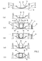
- Fig. 1a shows a first half-shell 10 of a rotor blade, which is arranged in a receiving device, not shown, or in the open mold used for the production of the half-shell. It is located in a predetermined position above the bottom 12 of an assembly hall, wherein the inside of the first half-shell 10 faces upward. Dashed lines show a dividing plane 14 of the rotor blade, which extends from the rotor blade leading edge to the rotor blade trailing edge.
- the first half-shell 10 has on the inside a main belt 16 which reinforces the first half-shell.
- a lowering device 18 consisting of a hydraulic cylinder 20 and a piston 22 is arranged on both sides of the first half-shell 10 is in each case a lowering device 18 consisting of a hydraulic cylinder 20 and a piston 22 is arranged.
- the lowering devices 18 are mounted on the floor 12 of the assembly hall.
- Fig. 1c additionally shows the bar holding device 26 which has a cross member 28 and further supports 30 protruding downwardly therefrom. Between the two other carriers 30 are two webs 32 of the rotor blade. The webs 32 have along their two half-shells facing longitudinal edges angled mounting portions 36 which allow a large-area contact in the connecting region with the two half-shells.
- the cross member 28 has in the region of its two ends in each case a non-illustrated abutment which rests on corresponding supports on the piston 22 of the two lowering devices 18.
- the cross member 28 preferably extends horizontally at a right angle to the longitudinal direction of the first half shell 10 and the two webs 32nd
- the movement takes place until a predetermined by at least one stop 23, which is a movement limiting device, predetermined end position is reached, which in the Fig. 1d ) is shown.
- the stopper 23 is fixedly arranged with respect to the web holding device 26 and cooperates with a stationary counterpart 34 standing on the ground 12.
- the webs 32 are in a position defined with respect to the parting plane 14 and at a distance from the first half shell 10. They are in contact with the adhesive 24 and are suspended above the inner contour of the first half shell 10.
- the defined distance and the precisely maintained desired geometry ensures a high-strength and adhesive-saving bonding between the webs 32 and the first half-shell 10 and the main belt 16, respectively.
- the web-holding device 26 is released from the webs 32 and removed. This condition is in the Fig. 1e ) illustrated. The two webs 32 are after completion of the guided movement of the web holding device 26 still in the exact predetermined end position.
- adhesive is applied to the upper angled mounting portions 36 of the webs 32, and the second half-shell 38 is placed by means of a suitable device. After curing of the adhesive, it is firmly connected to the two webs 32.
- a connection between the first half-shell 10 and the second half-shell 38 in particular also by gluing in the region of the contact surfaces.
- the second half-shell 38 also has a main belt 40 which extends longitudinally along the inside of the first half-shell 10.
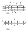
- FIGS. 2a) and 2b ) show a sectional view of the side view of the bar holding device according to the invention as shown in the Figures 1c) and 1d ).
- Fig. 2a is the web holding device 26 with the attached webs 32 in a predetermined position, wherein between the webs 32 and the first half-shell 10, a relatively large distance remains. Starting from this position, lowering the bar holding device 26 by opening a valve of the hydraulic cylinder 20. The bar holding device 26 with the webs attached thereto 32 moves to the first half-shell 10, because of the guide formed by the lowering 18 while adhering to a fixed predetermined direction of movement, in the example shown vertically downwards, and in compliance with a defined angular position.
- the movement takes place until a predetermined by at least one stop end position is reached, which in the Fig. 2b ) is shown.
- the webs 32 are in a position defined with respect to the parting plane 14. It is clearly recognizable here that the web is not deposited on the first half-shell, but is positioned at a distance h from the first half-shell 10.
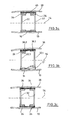
- FIGS. 3a) and 3b ) show a cross section through a rotor blade with incorrectly inserted webs 32, wherein for the installation of the webs 32 not the inventive method was used.
- Fig. 3a are the webs 32 sunken due to a low viscosity of the adhesive under its own weight in the applied adhesive until it is on the main belt 16 of the first Half shell 10 rest. In these contact areas, the adhesive is almost completely displaced, and there is no sufficient cohesive connection between web 32 and main belt 16.
- the resulting between the webs 32 and the main belt 40 of the second half-shell 38 height difference is by an oversized adhesive application 24 between the webs 32 and the second half-shell 38 balanced.
- the Fig. 3b shows a section through a rotor blade, in which the main belt 16 of the first blade half shell 10 has a one-sided shaft 17. Through this shaft 17, the punctiform resting web 32.1 tilts in the longitudinal direction and receives a higher position with respect to the parting plane 14.
- the second web 32.2 was placed in a belt region with normal cross-section, but is sunk to the main belt 16.
- the attachment portions 36.1, 36.2 of the webs 32.1, 32.2 thereby have a different distance to the parting plane 14.
- the second half-shell 38 is pulled down when placed on the first half-shell 10 by means of a form-closure device, not shown, whereby the applied to the mounting portion 36.1 of the first web adhesive is displaced.
- the Fig. 3c shows a cross section through a rotor blade with webs 32 used according to the method / device according to the invention.
- the webs 32 are located in a precisely defined position relative to the parting plane 14 and thus at a distance from the first and second half-shell 10, 38.
Landscapes
- Engineering & Computer Science (AREA)
- Mechanical Engineering (AREA)
- Life Sciences & Earth Sciences (AREA)
- Sustainable Development (AREA)
- Sustainable Energy (AREA)
- Chemical & Material Sciences (AREA)
- Combustion & Propulsion (AREA)
- General Engineering & Computer Science (AREA)
- Wind Motors (AREA)
Applications Claiming Priority (1)
| Application Number | Priority Date | Filing Date | Title |
|---|---|---|---|
| DE102009024324A DE102009024324A1 (de) | 2009-05-29 | 2009-05-29 | Verfahren und Vorrichtung zur Montage eines Rotorblatts für eine Windenergieanlage |
Publications (3)
| Publication Number | Publication Date |
|---|---|
| EP2261501A2 true EP2261501A2 (fr) | 2010-12-15 |
| EP2261501A3 EP2261501A3 (fr) | 2013-01-16 |
| EP2261501B1 EP2261501B1 (fr) | 2014-05-07 |
Family
ID=42812185
Family Applications (1)
| Application Number | Title | Priority Date | Filing Date |
|---|---|---|---|
| EP10005443.6A Not-in-force EP2261501B1 (fr) | 2009-05-29 | 2010-05-26 | Méthode et dispositif de montage d'une pale de rotor pour une éolienne |
Country Status (5)
| Country | Link |
|---|---|
| US (1) | US8454791B2 (fr) |
| EP (1) | EP2261501B1 (fr) |
| DE (1) | DE102009024324A1 (fr) |
| DK (1) | DK2261501T3 (fr) |
| ES (1) | ES2484943T3 (fr) |
Cited By (9)
| Publication number | Priority date | Publication date | Assignee | Title |
|---|---|---|---|---|
| GB2477847A (en) * | 2010-02-10 | 2011-08-17 | Albert Edward David Walters | Wind turbine blade with connecting elements |
| CN102794724A (zh) * | 2011-05-25 | 2012-11-28 | 迪皮埃复材构件(太仓)有限公司 | 一种腹板定位工装装置 |
| WO2013164101A1 (fr) * | 2012-05-03 | 2013-11-07 | Dürr Systems GmbH | Dispositif de fabrication de pales de rotor et procédé afférent |
| WO2015078561A1 (fr) * | 2013-11-28 | 2015-06-04 | Senvion Se | Dispositif de mise en place de barre, barre et procédé de fabrication d'une pale de rotor d'une éolienne |
| EP2918399A1 (fr) * | 2014-03-10 | 2015-09-16 | Siemens Aktiengesellschaft | Procédé de fabrication de pale de rotor d'éolienne |
| CN110267800A (zh) * | 2017-01-12 | 2019-09-20 | 维斯塔斯风力系统有限公司 | 用于组装具有内部腹板的风力涡轮机叶片的方法和设备 |
| US10864690B2 (en) | 2015-09-15 | 2020-12-15 | Vestas Wind Systems A/S | Wind turbine blade manufacturing method or apparatus |
| WO2021190973A1 (fr) * | 2020-03-26 | 2021-09-30 | LM Wind Power R&D (Holland) B.V. | Procédé de fabrication d'un ensemble pale d'éolienne et âme de cisaillement pour pale d'éolienne |
| WO2022053544A1 (fr) * | 2020-09-10 | 2022-03-17 | Lm Wind Power A/S | Système et procédé de fixation d'un composant de pale d'éolienne à une partie de coque de pale d'éolienne |
Families Citing this family (22)
| Publication number | Priority date | Publication date | Assignee | Title |
|---|---|---|---|---|
| CN102022254B (zh) * | 2009-09-23 | 2014-12-17 | 固瑞特模具(太仓)有限公司 | 风轮机叶片及其生产方法 |
| DE102010042327A1 (de) * | 2010-10-12 | 2012-04-12 | Repower Systems Se | Fertigung eines Rotorblattes einer Windenergieanlage |
| ES2399259B1 (es) * | 2011-05-24 | 2014-02-28 | Gamesa Innovation & Technology, S.L. | Un método de unión para una pala de aerogenerador multi-panel. |
| GB2497578B (en) | 2011-12-16 | 2015-01-14 | Vestas Wind Sys As | Wind turbine blades |
| CA2863288C (fr) | 2012-02-02 | 2020-09-15 | Lm Wp Patent Holding A/S | Systeme de serrage concu pour une pale d'eolienne |
| DE102012003378B4 (de) * | 2012-02-22 | 2015-01-29 | Nordex Energy Gmbh | Verfahren zum Herstellen einer Blindverklebung zwischen zwei Bauteilen eines Windenergieanlagenrotorblatts |
| DE102012109403B3 (de) * | 2012-10-02 | 2014-03-06 | Repower Systems Se | Verfahren zur Montage eines Rotorblattes und Montageanordnung |
| CN104995400B (zh) | 2012-12-20 | 2018-03-20 | 维斯塔斯风力系统有限公司 | 风轮机叶片抗剪腹板的对准 |
| GB2529186A (en) * | 2014-08-12 | 2016-02-17 | Vestas Wind Sys As | Improvements relating to wind turbine blade manufacture |
| US10690111B2 (en) | 2016-12-02 | 2020-06-23 | General Electric Company | Wind turbine rotor blade |
| DE102017102368A1 (de) * | 2017-02-07 | 2018-08-09 | J. Schmalz Gmbh | Vorrichtung zum Handhaben von Stegen sowie Verfahren zum Handhaben von Stegen für Rotorblätter |
| US10828843B2 (en) * | 2017-03-16 | 2020-11-10 | General Electric Company | Shear webs for wind turbine rotor blades and methods for manufacturing same |
| DE102017105935B4 (de) | 2017-03-20 | 2021-09-02 | Preh Gmbh | Verfahren zum vollflächigen Verbinden von antiparallel verlaufenden Kontaktflächen eines ersten und zweiten Fügepartners mittels eines Formlings |
| US11585319B2 (en) | 2017-11-07 | 2023-02-21 | Vestas Wind Systems A/S | Wind turbine blade manufacture |
| US20190152128A1 (en) * | 2017-11-21 | 2019-05-23 | General Electric Company | Vacuum Forming Mold Assembly and Related Methods of Use |
| ES2967599T3 (es) * | 2018-12-20 | 2024-05-03 | Vestas Wind Sys As | Mejoras con respecto a la fabricación de palas de turbina eólica |
| CN113423948B (zh) | 2018-12-20 | 2023-10-20 | 维斯塔斯风力系统有限公司 | 与风力涡轮机叶片制造相关的改进 |
| CN211343232U (zh) * | 2019-07-29 | 2020-08-25 | 中材科技风电叶片股份有限公司 | 腹板、腹板制造用模具以及叶片 |
| CN120080561A (zh) * | 2019-12-24 | 2025-06-03 | 中材科技风电叶片股份有限公司 | 腹板组装工装及叶片成型方法 |
| CN116408990A (zh) * | 2021-12-31 | 2023-07-11 | 苏州天顺复合材料科技有限公司 | 一种风电叶片自动流水智能制造方法 |
| WO2023232221A1 (fr) * | 2022-05-30 | 2023-12-07 | Lm Wind Power A/S | Procédé de fabrication de bandes de cisaillement pour pales de rotor |
| CN119878454A (zh) * | 2024-12-31 | 2025-04-25 | 江苏广大鑫盛精密智造有限公司 | 一种风电叶片支撑装置 |
Family Cites Families (11)
| Publication number | Priority date | Publication date | Assignee | Title |
|---|---|---|---|---|
| US1765023A (en) * | 1928-08-07 | 1930-06-17 | Mcwane Cast Iron Pipe Company | Crane rig |
| US3154338A (en) * | 1962-05-03 | 1964-10-27 | Regis L Pelphrey | Rail lifting device |
| DE3014347C2 (de) * | 1980-04-15 | 1983-05-26 | Messerschmitt-Bölkow-Blohm GmbH, 8000 München | Verfahren zur Herstellung von schaumkerngestützen, faserverstärkten Kunststoff-Formkörpern wie Flügel, Rotorblätter etc. großer Längen-und Breitenausdehnung |
| US4736976A (en) * | 1986-03-03 | 1988-04-12 | Berzenye Michael L | Pipe hook |
| FR2640006B1 (fr) * | 1988-12-05 | 1991-03-29 | Armines | Procede d'assemblage, par collage, de deux pieces ou substrats |
| DK175718B1 (da) * | 2002-04-15 | 2005-02-07 | Ssp Technology As | Möllevinge |
| NL1024326C2 (nl) * | 2003-09-19 | 2005-03-22 | Lely Entpr Ag | Inrichting voor het grijpen en verplaatsen van materiaal, zoals bijvoorbeeld ruwvoer. |
| ATE534817T1 (de) * | 2004-06-30 | 2011-12-15 | Vestas Wind Sys As | Aus zwei getrennten teilen hergestellte windturbinenflügel |
| DE102004057979C5 (de) * | 2004-11-30 | 2019-09-26 | Senvion Gmbh | Rotorblatt |
| ATE364494T1 (de) * | 2005-02-24 | 2007-07-15 | Vestas Wind Sys As | Verfahren zur herstellung eines windturbinenblatts, eine produktionsanlage von windturbinenblättern und verwendung hiervon |
| US7895745B2 (en) * | 2007-03-09 | 2011-03-01 | General Electric Company | Method for fabricating elongated airfoils for wind turbines |
-
2009
- 2009-05-29 DE DE102009024324A patent/DE102009024324A1/de not_active Withdrawn
-
2010
- 2010-05-26 EP EP10005443.6A patent/EP2261501B1/fr not_active Not-in-force
- 2010-05-26 DK DK10005443.6T patent/DK2261501T3/da active
- 2010-05-26 ES ES10005443.6T patent/ES2484943T3/es active Active
- 2010-05-27 US US12/788,932 patent/US8454791B2/en not_active Expired - Fee Related
Non-Patent Citations (1)
| Title |
|---|
| None |
Cited By (15)
| Publication number | Priority date | Publication date | Assignee | Title |
|---|---|---|---|---|
| GB2477847B (en) * | 2010-02-10 | 2014-01-22 | Albert Edward David Walters | Improvements in or relating to methods of manufacture |
| GB2477847A (en) * | 2010-02-10 | 2011-08-17 | Albert Edward David Walters | Wind turbine blade with connecting elements |
| CN102794724B (zh) * | 2011-05-25 | 2015-11-18 | 迪皮埃复材构件(太仓)有限公司 | 一种腹板定位工装装置 |
| CN102794724A (zh) * | 2011-05-25 | 2012-11-28 | 迪皮埃复材构件(太仓)有限公司 | 一种腹板定位工装装置 |
| WO2013164101A1 (fr) * | 2012-05-03 | 2013-11-07 | Dürr Systems GmbH | Dispositif de fabrication de pales de rotor et procédé afférent |
| WO2015078561A1 (fr) * | 2013-11-28 | 2015-06-04 | Senvion Se | Dispositif de mise en place de barre, barre et procédé de fabrication d'une pale de rotor d'une éolienne |
| EP2918399A1 (fr) * | 2014-03-10 | 2015-09-16 | Siemens Aktiengesellschaft | Procédé de fabrication de pale de rotor d'éolienne |
| US9889619B2 (en) | 2014-03-10 | 2018-02-13 | Siemens Aktiengesellschaft | Method for manufacturing a rotor blade for a wind turbine |
| US10864690B2 (en) | 2015-09-15 | 2020-12-15 | Vestas Wind Systems A/S | Wind turbine blade manufacturing method or apparatus |
| CN110267800A (zh) * | 2017-01-12 | 2019-09-20 | 维斯塔斯风力系统有限公司 | 用于组装具有内部腹板的风力涡轮机叶片的方法和设备 |
| CN110267800B (zh) * | 2017-01-12 | 2021-01-12 | 维斯塔斯风力系统有限公司 | 用于组装具有内部腹板的风力涡轮机叶片的方法和设备 |
| US11072129B2 (en) | 2017-01-12 | 2021-07-27 | Vestas Wind Systems A/S | Method and apparatus for assembling a wind turbine blade having an internal web |
| WO2021190973A1 (fr) * | 2020-03-26 | 2021-09-30 | LM Wind Power R&D (Holland) B.V. | Procédé de fabrication d'un ensemble pale d'éolienne et âme de cisaillement pour pale d'éolienne |
| WO2022053544A1 (fr) * | 2020-09-10 | 2022-03-17 | Lm Wind Power A/S | Système et procédé de fixation d'un composant de pale d'éolienne à une partie de coque de pale d'éolienne |
| US20230258156A1 (en) * | 2020-09-10 | 2023-08-17 | Lm Wind Power A/S | System and method for attaching a wind turbine blade component to a wind turbine blade shell part |
Also Published As
| Publication number | Publication date |
|---|---|
| US20110126978A1 (en) | 2011-06-02 |
| US8454791B2 (en) | 2013-06-04 |
| EP2261501A3 (fr) | 2013-01-16 |
| EP2261501B1 (fr) | 2014-05-07 |
| DE102009024324A1 (de) | 2010-12-02 |
| DK2261501T3 (da) | 2014-08-11 |
| ES2484943T3 (es) | 2014-08-12 |
Similar Documents
| Publication | Publication Date | Title |
|---|---|---|
| EP2261501B1 (fr) | Méthode et dispositif de montage d'une pale de rotor pour une éolienne | |
| EP2512765B1 (fr) | Dispositif de fabrication d'un fuselage constitué d'un matériau renforcé par des fibres pour un aéronef | |
| AT510694B1 (de) | Modul zum halten von mindestens einer hülse | |
| EP2532883B1 (fr) | Composant d'éolienne avec un câble électrique incorporé dans un laminage | |
| DE102005026010A1 (de) | Verfahren zur Herstellung einer verstärkten Schale zur Bildung von Teilkomponenten für Luftfahrzeuge sowie Schale zur Bildung von Teilkomponenten für Luftfahrzeuge | |
| EP2273103A2 (fr) | Pale de rotor pour une éolienne et son procédé de fabrication | |
| EP2666615B1 (fr) | Procédé de fabrication d'une demi-coque pour pale de rotor d'éolienne ou d'une pale de rotor d'éolienne et moule de fabrication à cette fin | |
| EP3496936A1 (fr) | Membrure en éléments préfabriqués pourvues de non-tissé et son procédé de production | |
| WO2013010645A1 (fr) | Dispositif et procédé de fabrication d'un élément de structure | |
| DE102018123531B4 (de) | Verfahren zum Installieren von Systemkomponenten in einem Abschnitt eines Flugzeugrumpfs | |
| EP2627899A1 (fr) | Fabrication d'une pale de rotor d'éolienne | |
| DE102012204858A1 (de) | Fertigung eines Faserverbundbauteils für ein Rotorblatt | |
| EP2712724A1 (fr) | Eléments de renforcement intégraux | |
| EP3074183B1 (fr) | Dispositif de mise en place de barre, barre et procédé de fabrication d'une pale de rotor d'une éolienne | |
| EP2662204A1 (fr) | Procédé, composant préfabriqué et moule de fabrication d'une pièce d'éolienne | |
| EP3286078B1 (fr) | Élément de gouverne | |
| EP2388194A2 (fr) | Positionnement de longeron | |
| DE102012003378B4 (de) | Verfahren zum Herstellen einer Blindverklebung zwischen zwei Bauteilen eines Windenergieanlagenrotorblatts | |
| DE102017126276A1 (de) | Verfahren zur Herstellung einer Steg-Gurt-Baugruppe für ein Windenergieanlagenrotorblatt und Steg-Gurt-Baugruppe | |
| DE102011117185B4 (de) | Haltevorrichtung zur Anbringung mindestens eines Anbauteils an eine Rumpfzellenstruktur eines Luftfahrzeuges | |
| DE102005030939A1 (de) | Verfahren zur Herstellung eines im Wesentlichen schalenförmigen Bauteils | |
| WO2019201738A1 (fr) | Pale de rotor d'éolienne et éolienne | |
| EP3578349A1 (fr) | Procédé et dispositif de fabrication d'une lame de rotor pour une éolienne ainsi qu'éolienne | |
| DE102011077609B4 (de) | Fertigung einer Rotorblattschale | |
| DE102010062870B4 (de) | Verfahren und Vorrichtung zur Herstellung eines Faserverbundbauteils in Integralbauweise |
Legal Events
| Date | Code | Title | Description |
|---|---|---|---|
| PUAI | Public reference made under article 153(3) epc to a published international application that has entered the european phase |
Free format text: ORIGINAL CODE: 0009012 |
|
| AK | Designated contracting states |
Kind code of ref document: A2 Designated state(s): AL AT BE BG CH CY CZ DE DK EE ES FI FR GB GR HR HU IE IS IT LI LT LU LV MC MK MT NL NO PL PT RO SE SI SK SM TR |
|
| AX | Request for extension of the european patent |
Extension state: BA ME RS |
|
| PUAL | Search report despatched |
Free format text: ORIGINAL CODE: 0009013 |
|
| AK | Designated contracting states |
Kind code of ref document: A3 Designated state(s): AL AT BE BG CH CY CZ DE DK EE ES FI FR GB GR HR HU IE IS IT LI LT LU LV MC MK MT NL NO PL PT RO SE SI SK SM TR |
|
| AX | Request for extension of the european patent |
Extension state: BA ME RS |
|
| RIC1 | Information provided on ipc code assigned before grant |
Ipc: B29D 99/00 20100101ALI20121211BHEP Ipc: F03D 1/06 20060101AFI20121211BHEP Ipc: B29C 65/48 20060101ALI20121211BHEP |
|
| 17P | Request for examination filed |
Effective date: 20130625 |
|
| RBV | Designated contracting states (corrected) |
Designated state(s): AL AT BE BG CH CY CZ DE DK EE ES FI FR GB GR HR HU IE IS IT LI LT LU LV MC MK MT NL NO PL PT RO SE SI SK SM TR |
|
| REG | Reference to a national code |
Ref country code: DE Ref legal event code: R079 Ref document number: 502010006854 Country of ref document: DE Free format text: PREVIOUS MAIN CLASS: F03D0001060000 Ipc: B29D0099000000 |
|
| GRAP | Despatch of communication of intention to grant a patent |
Free format text: ORIGINAL CODE: EPIDOSNIGR1 |
|
| RIC1 | Information provided on ipc code assigned before grant |
Ipc: F03D 1/06 20060101ALI20140122BHEP Ipc: B29C 65/00 20060101ALI20140122BHEP Ipc: B29D 99/00 20100101AFI20140122BHEP Ipc: B29C 65/48 20060101ALI20140122BHEP Ipc: B29L 31/08 20060101ALI20140122BHEP |
|
| INTG | Intention to grant announced |
Effective date: 20140214 |
|
| GRAS | Grant fee paid |
Free format text: ORIGINAL CODE: EPIDOSNIGR3 |
|
| GRAA | (expected) grant |
Free format text: ORIGINAL CODE: 0009210 |
|
| AK | Designated contracting states |
Kind code of ref document: B1 Designated state(s): AL AT BE BG CH CY CZ DE DK EE ES FI FR GB GR HR HU IE IS IT LI LT LU LV MC MK MT NL NO PL PT RO SE SI SK SM TR |
|
| REG | Reference to a national code |
Ref country code: GB Ref legal event code: FG4D Free format text: NOT ENGLISH |
|
| REG | Reference to a national code |
Ref country code: AT Ref legal event code: REF Ref document number: 666271 Country of ref document: AT Kind code of ref document: T Effective date: 20140515 |
|
| REG | Reference to a national code |
Ref country code: IE Ref legal event code: FG4D Free format text: LANGUAGE OF EP DOCUMENT: GERMAN |
|
| REG | Reference to a national code |
Ref country code: DE Ref legal event code: R096 Ref document number: 502010006854 Country of ref document: DE Effective date: 20140618 |
|
| RAP2 | Party data changed (patent owner data changed or rights of a patent transferred) |
Owner name: NORDEX ENERGY GMBH |
|
| REG | Reference to a national code |
Ref country code: DK Ref legal event code: T3 Effective date: 20140804 |
|
| REG | Reference to a national code |
Ref country code: ES Ref legal event code: FG2A Ref document number: 2484943 Country of ref document: ES Kind code of ref document: T3 Effective date: 20140812 |
|
| REG | Reference to a national code |
Ref country code: NL Ref legal event code: VDEP Effective date: 20140507 |
|
| REG | Reference to a national code |
Ref country code: LT Ref legal event code: MG4D |
|
| PG25 | Lapsed in a contracting state [announced via postgrant information from national office to epo] |
Ref country code: LT Free format text: LAPSE BECAUSE OF FAILURE TO SUBMIT A TRANSLATION OF THE DESCRIPTION OR TO PAY THE FEE WITHIN THE PRESCRIBED TIME-LIMIT Effective date: 20140507 Ref country code: IS Free format text: LAPSE BECAUSE OF FAILURE TO SUBMIT A TRANSLATION OF THE DESCRIPTION OR TO PAY THE FEE WITHIN THE PRESCRIBED TIME-LIMIT Effective date: 20140907 Ref country code: CY Free format text: LAPSE BECAUSE OF FAILURE TO SUBMIT A TRANSLATION OF THE DESCRIPTION OR TO PAY THE FEE WITHIN THE PRESCRIBED TIME-LIMIT Effective date: 20140507 Ref country code: NO Free format text: LAPSE BECAUSE OF FAILURE TO SUBMIT A TRANSLATION OF THE DESCRIPTION OR TO PAY THE FEE WITHIN THE PRESCRIBED TIME-LIMIT Effective date: 20140807 Ref country code: GR Free format text: LAPSE BECAUSE OF FAILURE TO SUBMIT A TRANSLATION OF THE DESCRIPTION OR TO PAY THE FEE WITHIN THE PRESCRIBED TIME-LIMIT Effective date: 20140808 Ref country code: FI Free format text: LAPSE BECAUSE OF FAILURE TO SUBMIT A TRANSLATION OF THE DESCRIPTION OR TO PAY THE FEE WITHIN THE PRESCRIBED TIME-LIMIT Effective date: 20140507 |
|
| PG25 | Lapsed in a contracting state [announced via postgrant information from national office to epo] |
Ref country code: SE Free format text: LAPSE BECAUSE OF FAILURE TO SUBMIT A TRANSLATION OF THE DESCRIPTION OR TO PAY THE FEE WITHIN THE PRESCRIBED TIME-LIMIT Effective date: 20140507 Ref country code: LV Free format text: LAPSE BECAUSE OF FAILURE TO SUBMIT A TRANSLATION OF THE DESCRIPTION OR TO PAY THE FEE WITHIN THE PRESCRIBED TIME-LIMIT Effective date: 20140507 Ref country code: HR Free format text: LAPSE BECAUSE OF FAILURE TO SUBMIT A TRANSLATION OF THE DESCRIPTION OR TO PAY THE FEE WITHIN THE PRESCRIBED TIME-LIMIT Effective date: 20140507 Ref country code: PL Free format text: LAPSE BECAUSE OF FAILURE TO SUBMIT A TRANSLATION OF THE DESCRIPTION OR TO PAY THE FEE WITHIN THE PRESCRIBED TIME-LIMIT Effective date: 20140507 |
|
| PG25 | Lapsed in a contracting state [announced via postgrant information from national office to epo] |
Ref country code: PT Free format text: LAPSE BECAUSE OF FAILURE TO SUBMIT A TRANSLATION OF THE DESCRIPTION OR TO PAY THE FEE WITHIN THE PRESCRIBED TIME-LIMIT Effective date: 20140908 |
|
| REG | Reference to a national code |
Ref country code: CH Ref legal event code: PL |
|
| PG25 | Lapsed in a contracting state [announced via postgrant information from national office to epo] |
Ref country code: LI Free format text: LAPSE BECAUSE OF NON-PAYMENT OF DUE FEES Effective date: 20140531 Ref country code: CH Free format text: LAPSE BECAUSE OF NON-PAYMENT OF DUE FEES Effective date: 20140531 Ref country code: EE Free format text: LAPSE BECAUSE OF FAILURE TO SUBMIT A TRANSLATION OF THE DESCRIPTION OR TO PAY THE FEE WITHIN THE PRESCRIBED TIME-LIMIT Effective date: 20140507 Ref country code: RO Free format text: LAPSE BECAUSE OF FAILURE TO SUBMIT A TRANSLATION OF THE DESCRIPTION OR TO PAY THE FEE WITHIN THE PRESCRIBED TIME-LIMIT Effective date: 20140507 Ref country code: CZ Free format text: LAPSE BECAUSE OF FAILURE TO SUBMIT A TRANSLATION OF THE DESCRIPTION OR TO PAY THE FEE WITHIN THE PRESCRIBED TIME-LIMIT Effective date: 20140507 Ref country code: SK Free format text: LAPSE BECAUSE OF FAILURE TO SUBMIT A TRANSLATION OF THE DESCRIPTION OR TO PAY THE FEE WITHIN THE PRESCRIBED TIME-LIMIT Effective date: 20140507 |
|
| REG | Reference to a national code |
Ref country code: DE Ref legal event code: R026 Ref document number: 502010006854 Country of ref document: DE |
|
| PLBI | Opposition filed |
Free format text: ORIGINAL CODE: 0009260 |
|
| REG | Reference to a national code |
Ref country code: IE Ref legal event code: MM4A |
|
| PG25 | Lapsed in a contracting state [announced via postgrant information from national office to epo] |
Ref country code: NL Free format text: LAPSE BECAUSE OF FAILURE TO SUBMIT A TRANSLATION OF THE DESCRIPTION OR TO PAY THE FEE WITHIN THE PRESCRIBED TIME-LIMIT Effective date: 20140507 |
|
| PLAX | Notice of opposition and request to file observation + time limit sent |
Free format text: ORIGINAL CODE: EPIDOSNOBS2 |
|
| 26 | Opposition filed |
Opponent name: ENERCON GMBH Effective date: 20150209 |
|
| REG | Reference to a national code |
Ref country code: FR Ref legal event code: ST Effective date: 20150303 |
|
| REG | Reference to a national code |
Ref country code: DE Ref legal event code: R026 Ref document number: 502010006854 Country of ref document: DE Effective date: 20150209 |
|
| GBPC | Gb: european patent ceased through non-payment of renewal fee |
Effective date: 20140807 |
|
| PG25 | Lapsed in a contracting state [announced via postgrant information from national office to epo] |
Ref country code: IE Free format text: LAPSE BECAUSE OF NON-PAYMENT OF DUE FEES Effective date: 20140526 Ref country code: IT Free format text: LAPSE BECAUSE OF FAILURE TO SUBMIT A TRANSLATION OF THE DESCRIPTION OR TO PAY THE FEE WITHIN THE PRESCRIBED TIME-LIMIT Effective date: 20140507 |
|
| PG25 | Lapsed in a contracting state [announced via postgrant information from national office to epo] |
Ref country code: FR Free format text: LAPSE BECAUSE OF NON-PAYMENT OF DUE FEES Effective date: 20140707 |
|
| PLAF | Information modified related to communication of a notice of opposition and request to file observations + time limit |
Free format text: ORIGINAL CODE: EPIDOSCOBS2 |
|
| PG25 | Lapsed in a contracting state [announced via postgrant information from national office to epo] |
Ref country code: GB Free format text: LAPSE BECAUSE OF NON-PAYMENT OF DUE FEES Effective date: 20140807 Ref country code: SI Free format text: LAPSE BECAUSE OF FAILURE TO SUBMIT A TRANSLATION OF THE DESCRIPTION OR TO PAY THE FEE WITHIN THE PRESCRIBED TIME-LIMIT Effective date: 20140507 |
|
| PLBB | Reply of patent proprietor to notice(s) of opposition received |
Free format text: ORIGINAL CODE: EPIDOSNOBS3 |
|
| PG25 | Lapsed in a contracting state [announced via postgrant information from national office to epo] |
Ref country code: MT Free format text: LAPSE BECAUSE OF FAILURE TO SUBMIT A TRANSLATION OF THE DESCRIPTION OR TO PAY THE FEE WITHIN THE PRESCRIBED TIME-LIMIT Effective date: 20140507 |
|
| PG25 | Lapsed in a contracting state [announced via postgrant information from national office to epo] |
Ref country code: SM Free format text: LAPSE BECAUSE OF FAILURE TO SUBMIT A TRANSLATION OF THE DESCRIPTION OR TO PAY THE FEE WITHIN THE PRESCRIBED TIME-LIMIT Effective date: 20140507 Ref country code: MC Free format text: LAPSE BECAUSE OF FAILURE TO SUBMIT A TRANSLATION OF THE DESCRIPTION OR TO PAY THE FEE WITHIN THE PRESCRIBED TIME-LIMIT Effective date: 20140507 |
|
| PG25 | Lapsed in a contracting state [announced via postgrant information from national office to epo] |
Ref country code: BG Free format text: LAPSE BECAUSE OF FAILURE TO SUBMIT A TRANSLATION OF THE DESCRIPTION OR TO PAY THE FEE WITHIN THE PRESCRIBED TIME-LIMIT Effective date: 20140507 |
|
| REG | Reference to a national code |
Ref country code: AT Ref legal event code: MM01 Ref document number: 666271 Country of ref document: AT Kind code of ref document: T Effective date: 20150526 |
|
| PG25 | Lapsed in a contracting state [announced via postgrant information from national office to epo] |
Ref country code: BE Free format text: LAPSE BECAUSE OF FAILURE TO SUBMIT A TRANSLATION OF THE DESCRIPTION OR TO PAY THE FEE WITHIN THE PRESCRIBED TIME-LIMIT Effective date: 20140531 Ref country code: LU Free format text: LAPSE BECAUSE OF NON-PAYMENT OF DUE FEES Effective date: 20140526 Ref country code: HU Free format text: LAPSE BECAUSE OF FAILURE TO SUBMIT A TRANSLATION OF THE DESCRIPTION OR TO PAY THE FEE WITHIN THE PRESCRIBED TIME-LIMIT; INVALID AB INITIO Effective date: 20100526 Ref country code: TR Free format text: LAPSE BECAUSE OF FAILURE TO SUBMIT A TRANSLATION OF THE DESCRIPTION OR TO PAY THE FEE WITHIN THE PRESCRIBED TIME-LIMIT Effective date: 20140507 |
|
| PG25 | Lapsed in a contracting state [announced via postgrant information from national office to epo] |
Ref country code: AT Free format text: LAPSE BECAUSE OF NON-PAYMENT OF DUE FEES Effective date: 20150526 |
|
| PLBD | Termination of opposition procedure: decision despatched |
Free format text: ORIGINAL CODE: EPIDOSNOPC1 |
|
| PLBP | Opposition withdrawn |
Free format text: ORIGINAL CODE: 0009264 |
|
| REG | Reference to a national code |
Ref country code: DE Ref legal event code: R100 Ref document number: 502010006854 Country of ref document: DE |
|
| PLBM | Termination of opposition procedure: date of legal effect published |
Free format text: ORIGINAL CODE: 0009276 |
|
| STAA | Information on the status of an ep patent application or granted ep patent |
Free format text: STATUS: OPPOSITION PROCEDURE CLOSED |
|
| 27C | Opposition proceedings terminated |
Effective date: 20170514 |
|
| PG25 | Lapsed in a contracting state [announced via postgrant information from national office to epo] |
Ref country code: MK Free format text: LAPSE BECAUSE OF FAILURE TO SUBMIT A TRANSLATION OF THE DESCRIPTION OR TO PAY THE FEE WITHIN THE PRESCRIBED TIME-LIMIT Effective date: 20140507 |
|
| PG25 | Lapsed in a contracting state [announced via postgrant information from national office to epo] |
Ref country code: AL Free format text: LAPSE BECAUSE OF FAILURE TO SUBMIT A TRANSLATION OF THE DESCRIPTION OR TO PAY THE FEE WITHIN THE PRESCRIBED TIME-LIMIT Effective date: 20140507 |
|
| REG | Reference to a national code |
Ref country code: DE Ref legal event code: R082 Ref document number: 502010006854 Country of ref document: DE Representative=s name: HAUCK PATENTANWALTSPARTNERSCHAFT MBB, DE Ref country code: DE Ref legal event code: R081 Ref document number: 502010006854 Country of ref document: DE Owner name: NORDEX ENERGY SE & CO. KG, DE Free format text: FORMER OWNER: NORDEX ENERGY GMBH, 22848 NORDERSTEDT, DE |
|
| PGFP | Annual fee paid to national office [announced via postgrant information from national office to epo] |
Ref country code: DE Payment date: 20210525 Year of fee payment: 12 |
|
| PGFP | Annual fee paid to national office [announced via postgrant information from national office to epo] |
Ref country code: ES Payment date: 20210618 Year of fee payment: 12 Ref country code: DK Payment date: 20210521 Year of fee payment: 12 |
|
| REG | Reference to a national code |
Ref country code: DE Ref legal event code: R119 Ref document number: 502010006854 Country of ref document: DE |
|
| REG | Reference to a national code |
Ref country code: DK Ref legal event code: EBP Effective date: 20220531 |
|
| PG25 | Lapsed in a contracting state [announced via postgrant information from national office to epo] |
Ref country code: DK Free format text: LAPSE BECAUSE OF NON-PAYMENT OF DUE FEES Effective date: 20220531 |
|
| PG25 | Lapsed in a contracting state [announced via postgrant information from national office to epo] |
Ref country code: DE Free format text: LAPSE BECAUSE OF NON-PAYMENT OF DUE FEES Effective date: 20221201 |
|
| REG | Reference to a national code |
Ref country code: ES Ref legal event code: FD2A Effective date: 20230727 |
|
| PG25 | Lapsed in a contracting state [announced via postgrant information from national office to epo] |
Ref country code: ES Free format text: LAPSE BECAUSE OF NON-PAYMENT OF DUE FEES Effective date: 20220527 |