EP2261945A1 - Disjoncteur - Google Patents
Disjoncteur Download PDFInfo
- Publication number
- EP2261945A1 EP2261945A1 EP09014246A EP09014246A EP2261945A1 EP 2261945 A1 EP2261945 A1 EP 2261945A1 EP 09014246 A EP09014246 A EP 09014246A EP 09014246 A EP09014246 A EP 09014246A EP 2261945 A1 EP2261945 A1 EP 2261945A1
- Authority
- EP
- European Patent Office
- Prior art keywords
- handle arm
- portions
- arm
- rotation
- supporting frame
- Prior art date
- Legal status (The legal status is an assumption and is not a legal conclusion. Google has not performed a legal analysis and makes no representation as to the accuracy of the status listed.)
- Granted
Links
Images









Classifications
-
- H—ELECTRICITY
- H01—ELECTRIC ELEMENTS
- H01H—ELECTRIC SWITCHES; RELAYS; SELECTORS; EMERGENCY PROTECTIVE DEVICES
- H01H71/00—Details of the protective switches or relays covered by groups H01H73/00 - H01H83/00
- H01H71/10—Operating or release mechanisms
- H01H71/50—Manual reset mechanisms which may be also used for manual release
- H01H71/52—Manual reset mechanisms which may be also used for manual release actuated by lever
- H01H71/521—Details concerning the lever handle
Definitions
- the present invention relates to a circuit breaker, such as a molded case circuit breaker and an earth leakage breaker, used in a switchboard of a power system.
- the upper link is driven indirectly via a main spring.
- An action stroke of the handle arm driving the main spring is set large in order to secure an operation margin.
- the rotational shaft center of the handle arm is disposed at an interphase position in the closest proximity to the bottom surface of the insulating case.
- the handle arm is supported in a rotatable manner on a supporting frame fixed at the interphase position close to the bottom portion of the insulating case. It is necessary to prevent the handle arm from undergoing lateral displacement in a direction in which the cross bar is extended.
- JP-UM-2-104549A describes the prevention of lateral displacement, particularly with reference to Fig. 1 through Fig. 3 .
- a circuit breaker is configured in such a manner that a circular protrusion portion is formed in the lower end portion of the handle arm and a concave circular portion corresponding to the circular protrusion portion is formed on the top surface of the supporting frame, so that the handle arm is supported on the supporting frame in a rotatable manner by fitting the circular protrusion portion of the handle arm in the concave circular portion of the supporting frame.
- circuit breaker is configured in such a manner that parts of the handle arm and the supporting frame are bent outward to form bent portions so that lateral displacement is prevented by engaging the bent portion of one member with the outer surface of the other member. These bent portions protrude outside noticeably beyond the required width of the handle arm or the supporting frame.
- the cross bar holding a movable contactor is disposed under the handle arm.
- the bent portions protruding noticeably to the outside of the handle arm and the supporting frame deteriorate insulation when securing phase-to-phase insulation of the movable contactor and thereby become a hindrance to enhancement of the breaking performance.
- An object of the invention is to provide a circuit breaker improved to be capable of solving the problems discussed above.
- a circuit breaker includes: a stationary contact disposed on an insulating base; a movable contactor having a movable contact that comes into contact with and moves apart from the stationary contact; a cross bar disposed on the insulating base in a rotatable manner and holding the movable contactor; a handle arm attached to a manually operated handle; a supporting frame fixed to the insulating base and axially supporting the handle arm in a rotatable manner; a rotary lever engaged with a latch of a tripping device and rotating when tripped; a lower link driving the cross bar; an upper link axially supported on the rotary lever and coupled to the lower link via a spring pin to form a toggle link; and a main spring interlocked with the handle arm at a drive end of the main spring and coupled to the spring pin at a driven end of the main spring.
- the circuit breaker is characterized in that: the handle arm is formed of a metal plate, and the handle arm has an arm base portion and a rotation center portion formed integrally with the arm base portion at its end portion; the supporting frame is formed of a metal plate, and the supporting frame has a frame base portion and a rotation support portion that is formed integrally with the frame base portion at its end portion, and the rotation support portion comes into contact with the rotation center portion of the handle arm; and one of the arm base portion and the frame base portion is provided with a thin wall formed integrally so as to be adjacent to the rotation center portion or the rotation support portion, and an inner surface or an outer surface of the thin wall is formed to be positioned between a plane containing an outer surface of the arm base portion or the frame base portion and a plane containing an inner surface thereof and thereby prevents the rotation center portion of the handle arm from undergoing displacement in a direction in which the cross bar is extended.
- the handle arm is formed of the metal plate, and the handle arm has the arm base portion and the rotation center portion formed integrally with the arm base portion at its end portion, and the supporting frame is formed of the metal plate, and the supporting frame has the frame base portion and the rotation support portion that is formed integrally with the frame base portion at its end portion and the rotation support portion comes into contact with the rotation center portion of the handle arm.
- one of the arm base portion and the frame base portion is provided with the thin wall formed integrally so as to be adjacent to the rotation center portion or the rotation support portion, and the inner surface or the outer surface of the thin wall is formed to be positioned between the plane containing the outer surface of the arm base portion or the frame base portion and the plane containing the inner surface thereof and thereby prevents the rotation center portion of the handle arm from undergoing displacement in the direction in which the cross bar is extended. It thus becomes possible not only to reduce a size of the circuit breaker but also to reduce the component costs while ensuring the phase-to-phase insulation performance.
- circuit breakers according to some embodiments of the invention will be described with reference to the drawings.
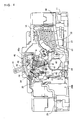
- Fig. 1 is a perspective view showing a circuit breaker according to a first embodiment of the invention in a trip state.
- Fig. 2 is a sectional side view showing the circuit breaker of the first embodiment in a trip state.
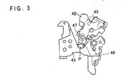
- Fig. 3 is a side view showing a handle arm, an upper link, a lower link, and a supporting frame extracted from Fig. 2 .
- Fig. 4 is a sectional side view showing the circuit breaker of the first embodiment in an OFF state.
- Fig. 5 is a side view showing the handle arm, the upper link, the lower link, and the supporting frame extracted from Fig. 4 .
- Fig. 6 is a sectional side view showing the circuit breaker of the first embodiment in an ON state.
- Fig. 1 is a perspective view showing a circuit breaker according to a first embodiment of the invention in a trip state.
- Fig. 2 is a sectional side view showing the circuit breaker of the first embodiment in a trip state.
- Fig. 3
- FIG. 7 is a side view showing the handle arm, the upper link, the lower link, and the supporting frame extracted from Fig. 6 .
- Fig. 8 is a front view showing the handle arm and the supporting frame of the first embodiment partially in cross section and with associated components.
- Fig. 9 (a) through Fig. 9(c) are exploded views showing the handle arm and the supporting frame of the first embodiment.
- the circuit breaker of the first embodiment is a three-phase circuit breaker and includes an insulating case 10 as is shown in Fig. 1 .
- the insulating case 10 has an insulting base 11 and an insulating cover 12.
- Circuit breaking units 20A, 20B, 20C in respective three phases are disposed on the insulating base 11 in parallel.
- An operation mechanism 40 is disposed above the circuit breaking unit 20B at the center.
- the insulating base 11 has a pair of outside walls 11A and 11B and a pair of partition walls 11C and 11D.
- the circuit breaking unit 20A is disposed between the outside wall 11A and the partition wall 11C.
- the circuit breaking unit 20B is disposed between the partition walls 11C and 11D.
- the circuit breaking unit 20C is disposed between the partition wall 11D and the outside wall 11B.
- the insulating cover 12 covers the circuit breaking units 20A, 20B, and 20C in the respective phases on the insulating base 11 and the operation mechanism 40.
- An operation handle 41 of the operation mechanism 40 protrudes from the insulating cover 12. It should be noted that Fig. 1 shows the interior by notching the insulating cover 12 in a portion covering the circuit breaking units 20A and 20B.
- the circuit breaking units 20A, 20B, and 20C in the respective phases are of the same configuration.
- the concrete configuration is shown in Fig. 2 , Fig. 4 , and Fig. 6 .
- Fig. 2 , Fig. 4 , and Fig. 6 show the circuit breaking unit 20B at the center and the other circuit breaking units 20A and 20C are the same as the circuit breaking unit 20B in configuration.
- a cross bar 30 is provided commonly for the circuit breaking units 20A, 20B, and 20C in the respective phases.
- the cross bar 30 is disposed on the insulating base 11 to be orthogonal to the circuit breaking units 20A, 20B, and 20C in the respective phases and shown in Fig. 2 , Fig. 4 , and Fig. 6 .
- Each of the circuit breaking units 20A, 20B, and 20C in the respective phases has a stationary contact 21, a movable contact 22, a movable contactor 23, and a pair of terminals 24 and 25.
- the stationary contact 21 is disposed on the insulating base 11 and connected to the terminal 24.
- the movable contact 22 is disposed on the movable contactor 23 oppositely to the stationary contact 21 and comes into contact with and moves apart from the stationary contact 21 in association with rotations of the movable contactor 23.
- the movable contactor 23 is connected to the terminal 25.
- the cross bar 30 is shown in Fig. 2 , Fig. 4 , and Fig. 6 .
- the cross bar 30 is disposed in the bottom portion of the insulating base 11 and extended to be orthogonal to the sheet surfaces of Fig. 2 , Fig. 4 , and Fig. 6 .
- the cross bar 30 is rotated about the shaft center by the operation mechanism 40.
- the movable contactors 23 of the circuit breaking units 20A, 20B, and 20C in the respective phases are attached to the cross bar 30.
- the movable contactors 23 of the circuit breaking units 20A, 20B, and 20C in the respective phases rotate simultaneously and the movable contacts 22 come into contact with or move apart from the corresponding stationary contact 21 in association with the rotations of the movable contactors 23.
- the operation mechanism 40 has the operation handle 41, a handle arm 42, a supporting frame 43, a rotary lever 44, an upper link 45, a lower link 46, a spring pin 47, and a main spring 48.
- the operation handle 41 is operated manually.
- the handle arm 42 is attached to the operation handle 41.
- the supporting frame 43 is fixed to the partition walls 11C and 11D of the insulating base 11.
- the handle arm 42 is supported on the supporting frame 43 in a rotatable manner.
- the rotation center point P of the handle arm 42 is shown in Fig. 2 through Fig. 7 .
- the operation handle 41 protrudes above from the insulating cover 12 and is rotated about the rotation center point P by a manual operation.
- the handle arm 42 In association with the rotation of the operation handle 41, the handle arm 42 is rotated about the rotation center point P with the operation handle 41.
- the handle arm 42 comes to an intermediate position in a trip state shown in Fig. 2 . It comes to a left inclined position in an OFF state shown in Fig. 4 and to a right inclined position in an ON state shown in Fig. 6 .
- the rotary lever 44 operates in cooperation with a latch 34 driven by an over current tripping device 33.
- the rotary lever 44 is normally kept pushed in a clockwise direction by the main spring 48.
- the over current tripping device 33 detects no over current
- the rotary lever 44 is engaged with the latch 34 and held in this state.
- the over current tripping device 33 trips the latch 34 upon detection of an over current
- the rotary lever 44 is disengaged from the latch 34 and starts to rotate in a clockwise direction.
- the upper link 45 is supported on a link supporting point Q of the rotary lever 44 in a rotatable manner at the upper end.
- the link supporting point Q is shown in Fig. 2 , Fig. 4 , and Fig. 6 .
- the upper end of the lower link 46 is interlocked with the lower end of the upper link 45 via the spring pin 47 in a rotatable manner, and the lower link 46 and the upper link 45 together form a toggle link.
- the lower end of the lower link 46 is interlocked with the cross bar 30 in a rotatable manner.
- the main spring 48 has a drive end 48a and a driven end 48b.
- the drive end 48a is coupled to the handle arm 42 and the driven end 48b is coupled to the spring pin 47.
- the drive end 48a of the main spring 48 moves about the rotation center point P of the handle arm 42 in a clockwise direction.
- the load direction of the main spring 48 varies, which causes the spring pin 47 to move rightward from the position shown in Fig. 4 .
- the lower link 46 becomes an upright standing state as shown in Fig. 6 and the cross bar 30 starts to rotate in a clockwise direction.
- the movable contact 22 on the movable contactor 23 thus comes into contact with the stationary contact 21 and the both become an ON state.
- the handle arm 42 rotates about the rotation center point P in a counter-clockwise direction with the operation handle 41 until the handle arm 42 reaches the left inclined position shown in Fig. 4 .
- the drive end 48a of the main spring 48 moves about the rotation center point P of the handle arm 42 in a counter-clockwise direction.
- the load direction of the main spring 48 varies, which causes the spring pin 47 to move leftward from the position shown in Fig. 6 .
- the lower link 46 returns to the horizontally oriented state as shown in Fig. 4 .
- the cross bar 30 then rotates in a counter-clockwise direction.
- the movable contact 22 on the movable contactor 23 thus moves apart from the stationary contact 21 and the both become an OFF state.
- the latch 34 moves and the latch 34 is disengaged from the rotary lever 44. Because the rotary lever 44 is normally kept pushed in a clockwise direction by the main spring 48, it starts to rotate in a clockwise direction when disengaged from the latch 34.
- the handle arm 42 rotates about the rotation center point P until the handle arm 42 reaches the intermediate position shown in Fig. 2 from the right inclined position shown in Fig. 6 .
- the drive end 48a of the main spring 48 relatively moves to be closer to the right side than the spring pin 47. An upward force thus starts to act on the spring pin 47.
- Fig. 3 shows the handle arm 42, the upper link 45, the lower link 46, and the supporting frame 43 extracted from Fig. 2 to show the relation in the trip state shown in Fig. 2 .
- Fig. 5 shows the handle arm 42, the upper link 45, the lower link 46, and the supporting frame 43 extracted from Fig. 4 to show the relation in the OFF state shown in Fig. 4 .
- Fig. 7 shows the handle arm 42, the upper link 45, the lower link 46, and the supporting frame 43 extracted from Fig. 6 to show the relation in the ON state shown in Fig. 6 .
- the handle arm 42 is supported on the supporting frame 43 at the rotation center point P in a rotatable manner and thereby rotates about the rotation center point P.
- the handle arm 42 is at the intermediate position in the trip state shown in Fig. 2 and Fig. 3 .
- the handle arm 42 is at the left inclined position provided by having rotated from the intermediate position in a counter-clockwise direction.
- the handle arm 42 In the ON state shown in Fig. 6 and Fig. 7 , the handle arm 42 is at the right inclined position provided by having rotated from the intermediate position in a clockwise direction.
- the lower link 46 is in the intermediate standing state in the trip state shown in Fig. 2 and Fig. 3 .
- the OFF state shown in Fig. 4 and Fig. 5 the lower link 46 is in the horizontally oriented state.
- the ON state shown in Fig. 6 and Fig. 7 the lower link 46 is in the upright standing state.
- Fig. 8 is a front view showing the handle arm 42 and the supporting frame 43 of the first embodiment partially in cross section and with associated component.
- the handle arm 42 is formed by bending a metal plate of a uniform thickness formed, for example, of an iron plate. As is shown in Fig. 8 , it has a top plate 421 and a pair of side plates 422 and 423.
- the side plates 422 and 423 making a pair extend from the both ends of the top plate 421 substantially parallel to each other.
- the side plates 422 and 423 making a pair have the same plate thickness and the same side surface shape.
- a pair of rotary levers 441 and 442, a pair of upper links 451 and 452, a pair of lower links 461 and 462, the spring pin 47, and a pair of main springs 481 and 482 are disposed between a pair of the side plates 422 and 423.
- the rotary levers 441 and 442 making a pair are formed in the same side surface shape from iron plates having the same plate thickness and disposed, respectively, on the inner surfaces of the side plates 422 and 423 of the handle arm 42 and form the rotary lever 44.
- the upper links 451 and 452 making a pair are formed in the same side surface shape from iron plates having the same plate thickness and form the upper link 45.
- the lower links 451 and 452 making a pair are also formed in the same side surface shape from iron plates having the same plate thickness and form the lower link 46.
- a pair of the lower links 461 and 462 is interlocked with a pair of the upper links 451 and 452 with the spring pin 47.
- the main springs 481 and 482 making a pair are formed as coil springs of the same shape and dimension and form the main spring 48.
- the drive ends 48a of the main springs 481 and 482 are engaged on the bottom surface of the top plate 421 of the handle arm 42 and the driven ends 48b are engaged at the spring pin 47.
- the supporting frame 43 is formed of a pair of frame plates 431 and 432.
- the frame plates 431 and 432 making a pair are formed in the same side surface shape from metal plates, for example, iron plates.
- the respective frame plates 431 and 432 are formed of iron plates having the same thickness as the plates forming the handle arm 42.
- the respective frame plates 431 and 432 have the same plate thickness as the respective side plates 422 and 423 of the handle arm 42.
- Figs . 9(a) through 9(c) are exploded views showing the handle arm 42 and the supporting frame 43 of the first embodiment.
- Fig. 9(a) is a front view of the handle arm 42.
- Fig. 9(b) is a sectional front view showing the supporting frame 43.
- Fig. 9(c) is a left side view of the handle arm 42.
- each has an arm base portion AB and a rotation center portion RC.
- the rotation center portion RC is formed continuously with the end portion of the arm base portion AB and is thereby formed integrally with the arm base portion AB.
- the arm base portions AB form the major portions of the side plates 422 and 423 and have a plate thickness t0.
- Each arm base portion AB has an inner surface s11 and an outer surface s21, and the inner surface s11 and the outer surface s21 are parallel to each other.
- the inner surfaces s11 of the respective arm base portions AB of a pair of the side plates 422 and 423 oppose each other with an interval D in between.
- the rotation center portions RC are portions that serve as the rotation center of the handle arm 42.
- the rotation center portions RC are supported on a pair of the frame plates 431 and 432 of the supporting frame 43 in a rotatable manner.
- the rotation center portions RC have a plate thickness t1.
- the plate thickness t1 of the rotation center portions RC and the plate thickness t0 of the arm base portions AB have the relation expressed as Equation (1) below.
- the plate thickness t1 is smaller than the plate thickness t0 by a dimension A.
- t ⁇ 1 t ⁇ 0 ⁇ A
- Each rotation center portion RC has an inner surface s12 and an outer surface s22, and the inner surface s12 and the outer surface s22 are parallel to each other.
- the inner surfaces s12 of the rotation center portions RC are present in the same planes as the inner surfaces s11 of the respective arm base portions AB.
- the inner surfaces s12 of the respective rotation center portions RC of a pair of the side plates 422 and 423 also oppose each other with an interval D in between.
- the outer surfaces s22 of the rotation center portions RC are positioned between the planes containing the inner surfaces s11 of the respective arm base portions AB and the planes containing the outer surfaces s21 of the respective arm base portions AB.
- the outer surfaces s22 are closer to the planes containing the inner surfaces s11 of the respective arm base portions AB than the planes containing the outer surfaces s21 thereof by the dimension A.
- the respective rotation center portions RC of a pair of the side plates 422 and 423 of the handle arm 42 protrude toward a pair of the frame plates 431 and 432 of the supporting frame 43 and convex circular rotation surfaces CR are formed on the protruding end surfaces.
- the rotation center portions RC are formed within a range of the plate thickness t0 of the arm base portions AB and therefore do not protrude outside beyond the range of the plate thickness t0 of the arm base portions AB.
- each has a frame base portion FB, a rotation support portion RS, and a thin wall TW.
- the rotation support portion RS and the thin wall TW are formed at the end portion of the frame base portion FB.
- the frame base portions FB form the major portions of a pair of the frame plates 431 and 432 and have a plate thickness t0.
- the plate thickness t0 is equal to the plate thickness of the arm base portions AB.
- Each of the frame base portions FB of a pair of the frame plates 431 and 432 has an inner surface s31 and an outer surface s41, and the inner surface s31 and the outer surface s41 are parallel to each other.
- the inner surfaces s31 of the respective frame base portions FB of a pair of the frame plates 431 and 432 oppose each other with an interval D in between.
- the interval D is equal to the interval between the inner surfaces s11 of the respective arm base portions AB of a pair of the side plates 422 and 423 of the handle arm 42.
- each rotation support portion RS of a pair of the frame plates 431 and 432 support the respective rotation center portions RC of a pair of the side plates 422 and 423 of the handle arm 42 in a rotatable manner.
- each rotation support portion RS is formed in a concave shape and has a concave circular support surface CS.
- the diameter of the circular support surfaces CS is nearly equal to the diameter of the corresponding circular rotation surfaces CR of the rotation center portions RC.
- the circular rotation surfaces CR and the circular support surfaces CS come into contact with each other at the rotation center point P shown in Fig. 2 through Fig. 7 .
- the handle arm 42 is thereby rotated about the rotation center point P.
- the circular support surfaces CS are formed with a width B from the corresponding inner surfaces s31 of the frame base portions FB.
- the thin wall TW provided adjacently to the rotation support portion RS is formed at the end of each frame base portion FB and is thereby formed integrally with the frame base portion FB.
- the thin walls TW are formed at the end portions of the respective frame base portions FB of a pair of the frame plates 431 and 432 on the side of the outer surfaces s41 of the frame base portions FB.
- the thin walls TW are also extended toward the rotation center portions RC of the handle arm 42 along the planes containing the outer surfaces s41 of the respective frame base portions FB.
- the thin walls TW have a thickness A.
- the thickness A is equal to the dimension A in Equation (1) above.
- Each thin wall TW has an inner surface s32 and an outer surface s42, and the inner surface s32 and the outer surface s42 are parallel to each other.
- the outer surfaces s42 of the thin walls TW are present in the same planes as the outer surfaces s41 of the respective frame base portions FB.
- the inner surfaces s32 of the thin walls TW are present between the planes containing the inner surfaces s31 of the respective frame base portions FB and the planes containing the outer surfaces s41 thereof.
- the thin walls TW together with the rotation support portions RS are provided to the frame plates 431 and 432 within a range of the plate thickness t0 of the frame base portions FB and therefore do not protrude outside beyond the range of the plate thickness t0.
- the inner surfaces s32 of the respective thin walls TW provided to a pair of the frame plates 431 and 432 come into contact with the outer surfaces s22 of the rotation center portions RC in a state where the circular support surfaces CS of the rotation support portions RS are in contact with the circular rotation surfaces CR of the rotation center portions RC and thereby prevent the handle arm 42 from undergoing displacement in the right-left direction of Fig. 9(a) , that is, in the direction in which the cross bar 30 is extended.
- the outer surfaces s42 of the respective thin walls TW provided to a pair of the frame plates 431 and 432 are positioned in the planes containing the outer surfaces s21 of the respective arm base portions AB of a pair of side plates 422 and 423 of the handle arm 42 in a state where the circular support surfaces CS of the rotation support portions RS are in contact with the circular rotation surfaces CR of the rotation center portions RC.
- the rotation center portions RC are formed within the range of the plate thickness t0 of the respective arm base portions AB of a pair of the side plates 422 and 423 of the handle arm 42 and the rotation support portions RS and the thin walls TW are formed within the range of the plate thickness t0 of the respective frame base portions FB of a pair of the frame plates 431 and 432 of the supporting frame 43. Consequently, all of the rotation center portions RC, the rotation support portions RS, and the thin walls TW are positioned within the range of the plate thickness t0 and therefore do not protrude outside beyond the range of the plate thickness t0.
- the rotation center portions RC, the rotation support portions RS, and the thin walls TW do not protrude outside beyond the required width of the handle arm 42 or the supporting frame 43.
- the handle arm 42 and the supporting frame 43 therefore fall within the required width. It thus becomes possible to achieve a size reduction of the circuit breaker by making the width dimension of the circuit breaker smaller.
- the breaking performance can be ensured when securing phase-to-phase insulation of the movable contactor 23 held by the cross bar 30 without the rotation center portions RC, the rotation support portions RS, and the thin walls TW deteriorating the insulation.
- the thin walls TW are also formed integrally with the frame base portions FB of the supporting frame 43, the assembly costs can be suppressed by reducing the component costs.
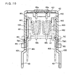
- Fig. 10 is a front view showing a handle arm and a supporting frame of a circuit breaker according to a second embodiment of the invention partially in cross section and with associated components.
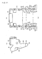
- Fig. 11(a) through Fig. 11(c) are exploded views showing the handle arm and the supporting frame of the circuit breaker of the second embodiment.
- Fig. 11(a) is a front view showing the handle arm of the circuit breaker of the second embodiment.
- Fig. 11(b) is a sectional front view showing the supporting frame of the circuit breaker of the second embodiment.
- Fig. 11(c) is a s ide view showing the handle arm of the circuit breaker of the second embodiment.
- a pair of the frame plates 431 and 432 of the supporting frame 43 of the first embodiment above is modified so as to have thin walls TW1.
- the thin walls TW1 are formed to slightly project outside from the outer surfaces s41 of the respective frame base portions FB.
- the supporting frame 43 is configured in the same manner as the supporting frame 43 of the first embodiment above.
- the circuit breaker of the second embodiment is configured in the same manner as the counterpart of the first embodiment above.
- the handle arm 42 is therefore configured in the same manner as the counterpart of the first embodiment above.
- the thin walls TW1 having a thickness A1 are formed at the end portions of the respective frame base portions FB of a pair of the frame plates 431 and 432 integrally with the frame base portions FB and adjacently to the rotation support portions RS.
- the thin walls TW1 slightly project from the outer surfaces s41.
- the thin walls TW1 are also extended parallel to the planes containing the outer surfaces s41.
- the thickness A1 is thicker than the thickness A of the thin walls TW of the supporting frame 43 employed in the first embodiment above and is thereby expressed as: A1 > A.
- the outer surfaces s42 of the thin walls TW1 are positioned slightly outside of the planes containing the outer surfaces s41 of the respective frame base portions FB whereas the inner surfaces s32 of the thin walls TW1 are positioned between the planes containing the outer surfaces s41 of the respective frame base portions FB and the planes containing the inner surfaces s31 of the respective frame base portions FB.
- the inner surfaces s32 of the thin walls TW1 are positioned between the planes containing the outer surfaces s41 of the frame base portions FB and the planes containing the inner surfaces s31 of the frame base portions FB, even when the dimension of projection of the outer surfaces s42 of the thin walls TW1 from the outer surfaces s41 of the frame base portion FB is set, for example, to 1/4 or less of the plate thickness t0 of the frame base portions FB, the thickness Al of the thin walls TW1 is sufficient to provide a required strength to the thin walls TW1.
- the rotation center portions RC are formed within the range of the plate thickness t0 of the respective arm base portions AB of a pair of the side plates 422 and 423 of the handle arm 42 and the rotation support portions RS are formed within the range of the plate thickness t0 of the respective frame base portions FB of a pair of the frame plates 431 and 432 of the supporting frame 43.
- the dimension of projection of the outer surfaces s42 of the thin walls TW1 from the outer surfaces s41 of the frame base portions FB of the frame plates 431 and 432 can be made smaller. Accordingly, the rotation center portions RC, the rotation support portions RS, and the thin walls TW1 do not protrude outside noticeably beyond the required width of the handle arm 42 or the supporting frame 43. The handle arm 42 and the supporting frame 43 can therefore fall substantially within the required width. It thus becomes possible to achieve a size reduction of the circuit breaker by making the width dimension of the circuit breaker smaller.
- the breaking performance can be ensured when securing phase-to-phase insulation of the movable contactor 23 held by the cross bar 30 without the rotation center portions RC, the rotation support portions RS, and the thin walls TW1 deteriorating the insulation.
- the thin walls TW1 are also formed integrally with the frame base portions FB of the supporting frame 43, the assembly costs can be suppressed by reducing the component costs.
- Fig. 12(a) through Fig. 12(c) are exploded views showing a handle arm and a supporting frame of a circuit breaker according to a third embodiment of the invention.
- Fig. 12(a) is a front view showing the handle arm of the circuit breaker of the third embodiment.
- Fig. 12 (b) is a sectional front view of the supporting frame of the circuit breaker of the third embodiment.
- Fig. 12(c) is left side view of the handle arm of the circuit breaker of the third embodiment.
- a handle arm 42A and a supporting frame 43 are formed of metal plates, such as iron plates, having different thicknesses.
- the supporting frame 43 and the handle arm 42A shown in Fig. 12(a) through Fig. 12(c) are employed.
- the supporting frame 43 is the same as the supporting frame 43 of the first embodiment above except that the inner surfaces s31 of the respective frame base portions FB of a pair of the frame plates 431 and 432 oppose each other with an interval D1 in between.
- the interval D1 is smaller than the interval D between the inner surfaces s31 of the respective frame base portions FB of the frame plates 431 and 432 of the supporting frame 43 of the first embodiment above.
- the handle arm 42A is formed of a thinner metal plate.
- the handle arm 42A is formed of an iron plate having a plate thickness t2 and the plate thickness t2 is expressed as: t2 ⁇ t0.
- the handle arm 42A has a top plate 421 and a pair of side plates 422 and 423.
- the top plates 421 and a pair of the side plates 422 and 423 are formed of iron plates having the plate thickness t2. As is shown in Fig.
- each has an arm base portion AB having the plate thickness t2 and a rotation center portion RC1 having the plate thickness t2.
- the inner surfaces s11 of the respective arm base portions AB of a pair of the side plates 422 and 423 oppose each other with the interval D1 in between.
- the rotation center portions RC1 are formed continuously with the end portions of the respective arm base portions AB and are thereby formed integrally with the arm base portions AB so as to project outside from the arm base portions AB.
- each rotation center portion RC1 has an inner surface s12 and an outer surface s22 parallel to each other and a convex circular rotation surface CR at the protrusion end.
- the supporting frame 43 same as the counterpart of the first embodiment above is employed and the respective frame base portions FB of a pair of the frame plates 431 and 432 of the supporting frame 43 have the plate thickness t0.
- the plate thickness t0 is expressed as: t0 > t2.
- the thin walls TW are formed to be adjacent to the respective rotation support portions RS1 in a state where the circular support surfaces CS of the rotation support portions RS formed at the end portions of the respective frame base portions FB of a pair of the frame plates 431 and 432 are in contact with the circular rotation surfaces CR of the rotation center portions RC1 formed at the end portions of the respective arm base portions AB of a pair of the side plates 422 and 423 of the handle arm 42A.
- These thin walls TW are formed integrally with the respective frame base portions FB of a pair of the frame plates 431 and 432.
- the inner surfaces s32 of the thin walls TW come into contact with the outer surfaces s22 of the rotation center portions RC1 and thereby prevent the handle arm 42A from undergoing displacement in the right-left direction of Fig. 12(a) , that is, in the direction in which the cross bar 30 is extended.
- the width B of the circular support surfaces CS is wider than the width of the circular rotation surfaces CR, that is, the plate thickness t2 of the rotation center portions RC1 and is thereby expressed as: B > t2. Accordingly, in a state where the outer surfaces s22 of the rotation center portions RC1 are in contact with the inner surfaces s32 of the thin walls TW, the circular rotation surfaces CR fall within the width B of the circular support surfaces CS.
- the third embodiment also achieves the effect same as the effect of the first embodiment above.
- the supporting frame 43 can be therefore standardized.
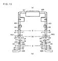
- Fig. 13(a) and Fig. 13(b) are exploded views showing a handle arm and a supporting frame of a circuit breaker according to a fourth embodiment of the invention.
- Fig. 13 (a) is a front view showing the handle arm of the circuit breaker of the fourth embodiment.
- Fig. 13 (b) is a sectional front view showing the supporting frame of the circuit breaker of the fourth embodiment.
- a handle arm 42B and a supporting frame 43B shown in Fig. 13(a) and Fig. 13(b) are employed.
- the outer surfaces s22 of rotation center portions RC2 formed at the end portions of the respective arm base portions A3 of a pair of the side plates 422 and 423 are in the same planes as the outer surfaces s21 of the respective arm base portions AB, and the inner surfaces s12 of rotation center portions RC2 are positioned outside from the planes containing the inner surfaces s11 of the respective arm base portions AB by a dimension A.
- the supporting frame 43B is provided with the thin walls TW extending along the planes containing the inner surfaces s31 and formed continuously and integrally with the frame base portions FB to be adjacent to the respective rotation support portions RS2.
- the circuit breaker of the fourth embodiment is configured in the same manner as the counterpart of the first embodiment above.
- the inner surfaces s11 of the respective arm base portions AB of a pair of the side plates 422 and 423 oppose each other with an interval D in between.
- the inner surfaces s12 of the rotation center portions RC2 formed at the end portions of the respective arm base portions AB of a pair of the side plates 422 and 423 oppose each other with an interval D3 larger than the interval D by 2 ⁇ A in between.
- the inner surfaces s31 of the respective frame base portions FB of a pair of the frame plates 431 and 432 oppose each other with an interval D in between.
- the inner surfaces s32 of the thin walls TW formed on the side of the inner surfaces s31 at the end portions of the respective frame base portions FB of a pair of the frame plates 431 and 432 are present on the same planes as the inner surfaces s31 of the respective frame base portions FB and oppose each other with an interval D in between.
- the thin walls TW are formed integrally with the respective frame base portions FB of a pair of the frame plates 431 and 432.
- the thin walls TW are formed at the end portions of the respective frame base portions FB of a pair of the frame plates 431 and 432 adjacently to the respective rotation support portions RS2.
- the outer surfaces s42 of the thin walls TW come into contact with the inner surfaces s12 of the respective rotation center portions RC2 in a state where the circular support surfaces CS of the rotation support portions RS2 formed at the end portions of the respective frame base portions FB of a pair of the frame plates 431 and 432 are in contact with the circular rotation surfaces CR of the rotation center portions RC2 formed at the end portions of the respective arm portions AB of a pair of the side plates 422 and 423 of the handle arm 42B and thereby prevent the handle arm 42B from undergoing displacement in the right-left direction of Fig. 13(a) , that is, in the direction in which the cross bar 30 is extended.
- the rotation center portions RC2 of the handle arm 42B are within the range of the plate thickness t0 of the arm base portions AB and the rotation support portions RS2 and the thin walls TW of the supporting frame 43B are within the range of the plate thickness t0 of the frame base portions FB.
- the effect same as the effect of the first embodiment above can be thus achieved.
- Fig. 14(a) and Fig. 14(b) are exploded views showing a handle arm and a supporting frame of a circuit breaker according to a fifth embodiment of the invention.
- Fig. 14(a) is a front view showing the handle arm of the circuit breaker of the fifth embodiment.
- Fig. 14(b) is a sectional front view showing the supporting frame of the circuit breaker of the fifth embodiment.
- the thin walls TW of the supporting frame 43B of the fourth embodiment above are replaced with thin walls TW1 similar to the thin walls TW1 of the second embodiment above.
- the supporting frame 43B of the fifth embodiment is configured in the same manner as the counterpart of the fourth embodiment above.
- the circuit breaker of the fifth embodiment is configured in the same manner as the counterpart of the fourth embodiment above.
- the supporting frame 43B is provided with the thin walls TW1 that are formed continuously and thereby integrally with the respective frame base portions FB to be adjacent to the rotation support portions RS2 on the side of the inner surfaces s31 at the end portions of the respective frame base portions FB of a pair of the frame plates 431 and 432 in such a manner as to project slightly inside from the inner surfaces s31 and extend along the planes containing the inner surfaces s31.
- the thin walls TW1 have a thickness Al.
- the inner surfaces s32 of the thin walls TW1 are positioned slightly inside from the planes containing the inner surfaces s31 of the respective frame base portions FB whereas the outer surfaces s42 of the thin walls TW1 are positioned between the planes containing the outer surfaces s41 of the respective frame base portions FB and the planes containing the inner surfaces s31 of the respective frame base portions FB.
- the outer surfaces s42 of the thin walls TW1 are positioned between the planes containing the outer surfaces s41 of the frame base portions FB and the planes containing the inner surfaces s31 of the frame base portions FB, even when the dimension of projection of the inner surfaces s32 of the thin walls TW1 from the inner surfaces s31 of the frame base portions FB is set, for example, to 1/4 or less of the plate thickness t0 of the frame base portions FB, the thickness Al of the thin walls TW1 is sufficient to provide a required strength to the thin walls TW1.
- the outer surfaces s42 of the thin walls TW1 formed at the end portions of the respective frame base portions FB of a pair of the frame plates 431 and 432 come into contact with the inner surfaces s12 of the rotation center portions RC2 in a state where the circular support surfaces CS of the rotation support portions RS2 formed at the end portions of the respective frame base portions FB of a pair of the frame plates 431 and 432 are in contact with the circular rotation surfaces CR of the rotation center portions RC2 formed at the end portions of the respective arm base portions AB of a pair of the side plates 422 and 423 of the handle arm 42B and thereby prevent the handle arm 42B from undergoing displacement in the right-left direction of Fig. 14(a) , that is, in the direction in which the cross bar 30 is extended.
- the rotation center portions RC2 are formed within the range of the plate thickness t0 of the respective arm base portions AB of a pair of the side plates 422 and 423 of the handle arm 42B.
- the rotation support portions RS2 are formed within the range of the plate thickness t0 of the respective frame base portions FB of a pair of the frame plates 431 and 432 of the supporting frame 43.
- the inner surfaces s32 of the thin walls TW1 slightly project from the inner surfaces s31 of the respective frame base portions FB
- the outer surfaces s42 are positioned between the planes containing the outer surfaces s41 of the respective frame base portions FB and the planes containing the inner surfaces s31 of the respective frame base portions FB.
- the outer surfaces s42 do not protrude outside of the frame plates 431 and 432.
- the rotation center portions RC2, the rotation support portions RS2, and the thin walls TW1 do not protrude outside beyond the required width of the handle arm 42B or the supporting frame 43B.
- the handle arm 42B and the supporting frame 43B therefore fall within the required width. It thus becomes possible to achieve a size reduction of the circuit breaker by making the width dimension of the circuit breaker smaller.
- the breaking performance can be ensured when securing phase-to-phase insulation of the movable contactor 23 held by the cross bar 30 without the rotation center portions RC2, the rotation support portions RS2, and the thin walls TW1 deteriorating the insulation.
- the thin walls TW1 are also formed integrally with the frame base portions FB of the supporting frame 43B, the assembly costs can be suppressed by reducing the component costs.
- Fig. 15(a) through Fig. 15(d) are exploded views showing a handle arm and a supporting frame of a circuit breaker according to a sixth embodiment of the invention.
- Fig. 15(a) is a front view showing the handle arm of the circuit breaker of the sixth embodiment.
- Fig. 15(b) is a sectional front view showing thE supporting frame of the circuit breaker of the sixth embodiment.
- Fig. 15(c) is a side view showing the handle arm of the circuit breaker of the sixth embodiment.
- Fig. 15(d) is a side view showing the supporting frame of the circuit breaker of the sixth embodiment.
- a handle arm 42C and a supporting frame 43C shown in Fig. 15(a) through Fig. 15(d) are employed.
- the handle arm 42C is a modification of the handle arm 42B of the fourth embodiment above and the rotation center portions RC3 are modified so as to have concave circular rotation surfaces CR on the end surfaces.
- the handle arm 42C is configured in the same as the handle arm 42B of the fourth embodiment above.
- the supporting frame 43C is a modification of the supporting frame 43B of the fourth embodiment above and the rotation support portions RS3 are modified so as to have convex circular support surfaces CS. As is shown in Fig.
- the rotation support portions RS3 are formed in a convex shape between concave portions C1 and C2 on both sides thereof.
- the supporting frame 43C is configured in the same manner as the supporting frame 43B of the fourth embodiment above.
- the thin walls TW are formed continuously with the end portions of the respective frame base portions FB of a pair of the frame plates 431 and 432 and are thereby formed integrally with the frame base portions FB.
- the thin walls TW are adjacent to the convex rotation support portions RS3 and the inner ends of the concave portions C1 and C2 at both ends thereof.
- the thin walls TW are also extended to a position higher than the rotation support portions RS3 along the planes containing the inner surfaces s31 of the respective frame base portions FB.
- the outer surfaces s42 of the thin walls TW come into contact with the inner surfaces s12 of the rotation center portions RC3 in a state where the circular support surfaces CS of the rotation support portions RS3 formed at the end portions of the respective frame base portions FB of a pair of the frame plates 431 and 432 are in contact with the circular rotation surfaces CR of the rotation center portions RC3 formed at the end portions of the respective arm base portions AB of a pair of the side plates 422 and 423 and thereby prevent the handle arm 42C from undergoing displacement in the right-left direction of Fig. 15(a) , that is, in the direction in which the cross bar 30 is extended.
- the sixth embodiment it is possible to obtain the effect similar to the effect of the fourth embodiment above.
- the area of the thin walls TW when viewed from the side surfaces can be enlarged, it becomes possible to further increase the mechanical strength of the thin walls TW.
- Fig. 16(a) through Fig. 16(d) are exploded views showing a handle arm and a supporting frame of a circuit breaker according to a seventh embodiment of the invention.
- Fig. 16(a) is a front view showing the handle arm of the circuit breaker of the seventh embodiment.
- Fig. 16(b) is a sectional front view showing the supporting frame of the circuit breaker of the seventh embodiment.
- Fig. 16(c) is a side view showing the handle arm of the circuit breaker of the seventh embodiment.
- Fig. 16(d) is a side view showing the supporting frame of the circuit breaker of the seventh embodiment.
- a handle arm 42D and a supporting frame 43D shown in Fig. 16(a) through Fig. 16(d) are employed.
- the handle arm 42D is a modification of the handle arm 42 of the first embodiment above
- the supporting frame 43D is a modification of the supporting frame 43 of the first embodiment above.
- the circuit breaker of the seventh embodiment is configured in the same manner as the counterpart of the first embodiment above.
- each has an arm base portion AB and a rotation center portion RC4, and the rotation center portion RC4 is formed at the end portion of the arm base portion AB continuously with the arm base portion AB and is thereby formed integrally with the arm base portion AB.
- the arm base portions AB form the major portions of the side plates 422 and 423 and have a plate thickness t0.
- Each arm base portion AB has an inner surface s11 and an outer surface s21, and the inner surface s11 and the outer surface s21 are parallel to each other.
- the inner surfaces s11 of the respective arm base portions AB of a pair of the side plates 422 and 423 of the handle arm 42D oppose each other with an interval D in between.
- the rotation center portions RC4 of the handle arm 42D are portions that serve as the rotation center of the handle arm 42D.
- the rotation center portions RC4 are supported on a pair of the frame plates 431 and 432 of the supporting frame 43D in a rotatable manner.
- the rotation center portions RC4 have a plate thickness t1.
- the plate thickness t1 of the rotation center portions RC4 and the plate thickness t0 of the arm base portions AB have a relation expressed as Equation (1) above. As is obvious from Equation (1) above, the plate thickness t1 is smaller than the plate thickness t0 by the dimension A.
- Each rotation center portion RC4 of the handle arm 42D has an inner surface s12 and an cuter surface s22, and the inner surface s12 and the outer surface s22 are parallel to each other.
- the inner surfaces s12 of the respective rotation center portions RC4 of the handle arm 42D are present in the same planes as the inner surfaces s11 of the respective arm base portions AB.
- the inner surfaces s12 of the respective rotation center portions RC4 of a pair of the side plates 422 and 423 also oppose each other with an interval D in between.
- the outer surfaces s22 of the rotation center portions RC4 of the handle arm 42D are positioned between the planes containing the inner surfaces s11 of the respective arm base portions AB and the planes containing the outer surfaces s21 of the respective arm base portions AB.
- the outer surfaces 22 are closer to the planes containing the inner surfaces s11 of the arm base portions AB than the planes containing the outer surfaces s21 thereof by the dimension A.
- the respective rotation center portions RC4 of a pair of the side plates 422 and 423 of the handle arm 42D protrude toward a pair of the frame plates 431 and 432 of the supporting frame 43D and convex circular rotation surfaces CR are formed on the protruding end surfaces.
- the handle arm 42D is provided with thin walls TW2 adjacently to the outer surfaces s22 of the respective rotation center portions RC4.
- the thin walls TW2 have a thickness A.
- the thin walls TW2 are formed continuously with the end portions of the respective arm base portions AB of a pair of the side plates 422 and 423 and are thereby formed integrally with the arm base portions AB.
- Each thin wall TW2 has an inner surface s32 and an outer surface s42, and the inner surface s32 and the outer surface s42 are parallel to each other. As is shown in Fig.
- the thin walls TW2 are formed in a circular shape across a wide angular range so as to cover the outer surfaces s22 of the rotation center potions RC4 and further to protrude to the outer periphery over the outer surfaces s22.
- the inner surfaces s32 of the thin walls TW2 come into contact with the outer surfaces s22 of the rotation center portions RC4. Meanwhile, the inner surfaces s32 of the thin walls TW2 also protrude to the outer periphery over the outer surfaces s22 of the rotation center portions RC4.
- the rotation center portions RC4 and the thin walls TW2 are formed within the range of the plate thickness t0 of the arm base portions AB and therefore do not protrude outside beyond the range of the plate thickness t0 of the arm base portions AB.
- each has a frame base portion FB and a rotation support portion RS4.
- the rotation support portion RS4 is formed at the end portion of the frame base portion FB.
- the frame base portions FB form the major portions of a pair of the frame plates 431 and 432 and have a plate thickness t0.
- the plate thickness t0 is equal to the thickness of the arm base portions AB of a pair of the side plates 422 and 423 of the handle arm 42D.
- each has an inner surface s31 and an outer surface s41, and the inner surface s31 and the outer surface s41 are parallel to each other.
- the inner surfaces s31 of the respective frame base portions FB of a pair of the frame plates 431 and 432 of the supporting frame 43D oppose each other with an interval D in between.
- the interval D is equal to the interval between the inner surfaces s11 of the respective arm base portions AB of a pair of the side plates 422 and 423 of the handle arm 42D.
- the rotation support portions RS4 are formed continuously with the end portions of the respective frame base portions FB of a pair of the frame plates 431 and 432 of the supporting frame 43D and are thereby formed integrally with the frame base portions FB.
- the rotation support portions RS4 support the rotation center portions RC4 of a pair of the side plates 422 and 423 of the handle arm 42D in a rotatable manner.
- the rotation support portions RS4 are formed in a concave shape and have concave circular support surfaces CS.
- the diameter of the circular support surfaces CS is made nearly equal to the diameter of the corresponding circular rotation surfaces CR of the rotation center portions RC4.
- the circular rotation surfaces CR and the circular support surfaces CS come into contact with each other at the rotation center point P shown in Fig. 2 through Fig. 7 .
- the handle arm 42D is thereby rotated about the rotation center point P.
- the circular support surfaces CS of the rotation support portions RS4 are formed with a width B from the inner surfaces s31 at the end portions of the respective frame base portions FB.
- the width B is expressed as Equation (2) above.
- Each rotation support portion RS4 has an inner surface s51 and an outer surface s61, and the inner surface s51 and the outer surface s61 are parallel to each other.
- the inner surfaces s51 are positioned in the same planes as the inner surfaces s31 of the respective frame base portions FB. Consequently, the outer surfaces s61 of the rotation support portions RS4 are closer to the inner surfaces s31 of the frame base portion FB than the planes containing the outer surfaces s41 of the frame base portion FB by the dimension A.
- the rotation support portions RS4 of the supporting frame 43D are formed within the range of the plate thickness t0 of the frame base portions FB and therefore do not protrude outside beyond the range of the plate thickness t0.
- the inner surfaces s32 of the thin walls TW2 provided to a pair of the side plates 422 and 423 of the handle arm 42D come, into contact with the outer surfaces s61 of the support portions RS4 in a state where the circular support surfaces CS of the rotation support portions RS4 are in contact with the circular rotation surfaces CR of the rotation center portions RC4 of the handle arm 42D and thereby prevent the handle arm 42D from undergoing displacement in the right-left direction of Fig. 16(a) , that is, in the direction in which the cross bar 30 is extended.
- the outer surfaces s42 of the thin walls TW2 are positioned in the planes containing the outer surfaces s41 of the frame base portions FB of a pair of the frame plates 431 and 432 of the supporting frame 43D in a state where the circular support surfaces CS of the rotation support portions RS4 are in contact with the circular rotation surfaces CR of the rotation center portions RC4 of the handle arm 42D.
- the rotation center portions RC4 and the thin walls TW2 are formed within the range of the plate thickness t0 of the respective arm base portions AB of a pair of the side plates 422 and 423 of the handle arm 42D.
- the rotation support portions RS4 are formed within the range of the plate thickness t0 of the respective frame base portions FB of a pair of the frame plates 431 and 432 of the supporting frame 43D. Consequently, all of the rotation center portions RC4, the thin walls TW2, and the rotation support portions RS4 are positioned within the range of the plate thickness t0 and therefore do not protrude outside beyond the range of the plate thickness t0.
- the breaking performance can be ensured when securing phase-to-phase insulation of the movable contactor 23 held by the cross bar 30 without the rotation center portions RC4, the thin walls TW2, and the rotation support portions RS4 deteriorating the insulation.
- the thin walls TW2 are also formed integrally with the arm base portions AB of the handle arm 42D, the assembly costs can be suppressed by reducing the component costs.
- the contact portions of the circular rotation surfaces CR and the circular support surfaces CS can be covered with the thin walls TW2 across a wide range, a lubricant agent applied on the contact portions can be maintained in a reliable manner, which makes it possible to prevent entrance of powder dust into the contact portions in a reliable manner.
- Fig. 17(a) through Fig. 17(d) are exploded views showing a handle arm and a supporting frame of a circuit breaker according to an eighth embodiment of the invention.
- Fig. 17(a) is a front view showing the handle arm of the circuit breaker of the eighth embodiment.
- Fig. 17 (b) is a sectional front view showing the supporting frame of the circuit breaker of the eighth embodiment.
- Fig. 17(c) is a side view showing the handle arm of the circuit breaker of the eighth embodiment.
- Fig. 17(d) is a side view showing the supporting frame of the circuit breaker of the eighth embodiment.
- a pair of the frame plates 422 and 423 of the handle arm 42D of the seventh embodiment above is modified so as to have thin walls TW3.
- the thin walls TW3 are formed to slightly project outside from the outer surfaces s41 of the respective arm base portions AB.
- the handle arm 42D of the eighth embodiment is configured in the same manner as the handle arm 42D of the seventh embodiment above.
- the circuit breaker of the eighth embodiment is configured in the same manner as the counterpart of the seventh embodiment above.
- the supporting frame 43D is therefore configured in the same manner as the counterpart of the seventh embodiment above.
- the thin walls TW3 having a thickness A1 are formed at the end portions of the respective arm base portions AB of a pair of the side plates 422 and 423 adjacently to the rotation center portions RC4 and are thereby formed integrally with the respective arm base portions AB.
- the thin walls TW3 slightly project from the outer surfaces s21.
- the thin walls TW3 are also extended parallel to the planes containing the outer surfaces s21.
- the thickness A1 is larger than the thickness A of the thin walls TW2 of the handle arm 42D employed in the seventh embodiment above and is thereby expressed as: Al > A.
- the outer surfaces s42 of the thin walls TW3 are positioned slightly outside of the planes containing the outer surfaces s21 of the respective arm base portions AB whereas the inner surfaces s32 of the thin walls TW3 are positioned between the planes containing the outer surfaces s21 of the arm base portions AB and the planes containing the inner surfaces s11 of the arm base portions AB.
- the inner surfaces s32 of the thin walls TW3 are positioned between the planes containing the outer surfaces s21 of the arm base portions AB and the planes containing the inner surfaces s11 of the arm base portions AB, even when the dimension of projection of the outer surfaces s42 of the thin walls TW3 from the outer surfaces s21 of the arm base portions AB is set, for example, to 1/4 or less of the plate thickness t0 of the arm base portions AB, the thickness A1 of the thin walls TW3 is sufficient to provide a required strength to the thin walls TW3.
- the inner surfaces s32 of the thin walls TW3 formed at the end portions of a pair of the side walls 422 and 423 come into contact with the outer surfaces s61 of the rotation support portions RS4 and thereby prevent the handle arm 42D from undergoing displacement in the right-left direction of Fig. 17A , that is, in the direction in which the cross bar 30 is extended.
- the rotation center portions RC4 are formed within the range of the plate thickness t0 of the respective arm portions AB of a pair of the side plates 422 and 423 of the handle arm 42D and the rotation support portions RS4 are formed within the range of the plate thickness t0 of the respective frame base portions FB of a pair of the frame plates 431 and 432 of the supporting frame 43D.
- the inner surfaces 32 of the thin walls TW3 are positioned between the planes containing the outer surfaces s21 of the arm base portions AB and the planes containing the inner surfaces s11 of the arm base portions AB, it becomes possible to reduce the dimension of projection of the outer surfaces s42 of the thin walls TW3 from the outer surfaces s21 of the respective arm base portions AB of the side plates 422 and 423. Accordingly, the rotation center portions RC4, the thin walls TW3, and the rotation support portions RS4 do not project outside noticeably beyond the required width of the handle arm 42D or the supporting frame 43D. The handle arm 42D and the supporting frame 43D therefore fall substantially within the required width. It thus becomes possible to achieve a size reduction of the circuit breaker by making the width dimension of the circuit breaker smaller.
- the breaking performance can be ensured when securing phase-to-phase insulation of the movable contactor 23 held by the cross bar 30 without the rotation center portions RC4, the thin walls TW3, and the rotation support portions RS4 deteriorating the insulation.
- the thin walls TW3 are also formed integrally with the arm base portions AB of the handle arm 42D, it becomes possible to suppress the assembly costs by reducing the component costs.
- Fig. 18(a) through Fig. 18(d) are exploded views showing a handle arm and a supporting frame of a circuit breaker according to a ninth embodiment of the invention.
- Fig. 18(a) is a front view showing the handle arm of the circuit breaker of the ninth embodiment.
- Fig. 18(b) is a sectional front view showing the supporting frame of the circuit breaker of the ninth embodiment.
- Fig. 18(c) is a side view showing the handle arm of the circuit breaker of the ninth embodiment.
- Fig. 18(d) is a side view showing the supporting frame of the circuit breaker of the ninth embodiment.
- a handle arm 42E and a supporting frame 43E shown in Fig. 18(a) through Fig. 18(d) are employed.
- the handle arm 42E is a modification of the handle arm 42 of the first embodiment above
- the supporting frame 43E is a modification of the supporting frame 43 of the first embodiment above.
- the circuit breaker of the ninth embodiment is configured in the same manner as the counterpart of the first embodiment above.
- each has an arm base portion AB and a rotation center portion RC5.
- the rotation center portion RC5 is formed at the end portion of the arm base portion AB continuously with the arm base portion AB and is thereby formed integrally with the arm base portion AB.
- the arm base portions AB form the major portions of the side plates 422 and 423 and have a plate thickness t0.
- Each arm base portion AB has an inner surface s11 nd an outer surface s21, and the inner surface s11 and the outer surface s21 are parallel to each other.
- the inner surfaces s11 of the respective arm base portions AB of a pair of the side plates 422 and 423 of the handle arm 42E oppose each other with an interval D in between.
- the rotation center portions RC5 are portions that serve as the rotation center of the handle arm 42E.
- the rotation center portions RC5 are supported on a pair of the frame plates 431 and 432 of the supporting frame 43E in a rotatable manner.
- the rotation center portions RC5 are formed in a concave shape and each has a concave circular rotation surface CR.
- the circular rotation surfaces CR are formed to have a width B from the planes containing the outer surface s21 of the respective arm base portions AB.
- Thin walls TW4 are formed adjacently to the respective rotation center portions RC5.
- the thin walls TW4 are formed continuously with the respective arm base portions AB and are thereby formed integrally with the arm base portions AB.
- the thin walls TW4 are also extended toward a pair of frame plates 431 and 432 of the supporting frame 43E.
- the thin walls TW4 have a thickness A.
- Each thin wall TW4 has an inner surface s32 and an outer surface s42, and the inner surface s32 and the outer surface s42 are parallel to each other.
- the inner surfaces s32 of the thin walls TW4 are present in the same planes as the inner surfaces s11 of the respective arm base portions AB.
- the thin walls TW4 cover the inner surface side of the circular rotation surfaces CR.
- the rotation center portions RC5 and the thin walls TW4 are formed within the range of the plate thickness t0 of the arm base portions AB and therefore do not protrude outside beyond the range of the plate thickness t0 of the arm base portions AB.
- each has a frame base portion FB and a rotation support portion RS5.
- the rotation support portions RS5 of the supporting frame 43E are formed integrally with the respective frame base portions FB at the end portions thereof.
- the frame base portions FB form the major portion of a pair of the frame plates 431 and 432 and have a plate thickness t0.
- the plate thickness t0 is equal to the thickness of the arm base portions AB of a pair of the side plates 422 and 423 of the handle arm 42E.
- each has an inner surface s31 and an outer surface s41, and the inner surface s31 and the outer surface s41 are parallel to each other.
- the inner surfaces s31 of the respective frame base portions FB of a pair of the frame plates 431 and 432 oppose each other with an interval D in between.
- the interval D is equal to the interval between the inner surfaces s11 of the respective arm base portions AB of a pair of the side plates 422 and 423 of the handle arm 42E.
- the rotation support portions RS5 are formed in a convex shape and each has a convex circular support surface CS.
- the diameter of the circular support surfaces CS is nearly equal to the diameter of the corresponding circular rotation surfaces CR of the rotation center portions RC5.
- the circular rotation surfaces CR and the circular support surfaces CS come into contact with each other at the rotation center point P shown in Fig. 2 through Fig. 7 .
- the handle arm 42E is thereby rotated about the rotation center point P.
- the outer surfaces s42 of the thin walls TW4 provided to a pair of the side plates 422 and 423 of the handle arm 42E come into contact with the inner surfaces s51 of the rotation support portions RS5 in a state where the circular support surfaces CS of the rotation support portion RS5 are in contact with the circular rotation surfaces CR of the rotation center portions RC5 of the handle arm 42E and thereby prevent the handle arm 42E from undergoing displacement in the right-left direction of Fig. 18(a) , that is, in the direction in which the cross bar 30 is extended.
- the inner surfaces s32 of the thin walls TW4 are positioned in the planes containing the inner surfaces s31 of the respective frame base portions FB of a pair of the frame plates 431 and 432 of the supporting frame 43E in a state where the circular support surfaces CS of the rotation support portions RS5 are in contact with the circular rotation surfaces CR of the rotation center portions RC5 of the handle arm 42E.
- the rotation center portions RC5 and the thin walls TW4 are formed within the range of the plate thickness t0 of the respective arm base portions AB of a pair of the side plates 422 and 423 of the handle arm 42E and the rotation support portions RS5 are formed within the range of the plate thickness t0 of a pair of the frame plates 431 and 432 of the supporting frame 43E. Consequently, all of the rotation center portions RC5, the thin walls TW4, and the rotation support portions RS5 are positioned within the range of the plate thickness t0 and therefore do not protrude outside beyond the range of the plate thickness t0.
- the rotation center portions RC5, the thin walls TW4, and the rotation support portions RS5 do not protrude outside beyond the required width of the handle arm 42E or the supporting frame 43E.
- the handle arm 42E and the supporting frame 43E therefore fall within the required width. It thus becomes possible to achieve a size reduction of the circuit breaker by making the width dimension of the circuit breaker smaller.
- the breaking performance can be ensured when securing phase-to-phase insulation of the movable contactor 23 held by the cross bar 30 without the rotation center portions RC5, the thin walls TW4, and the rotation support portions RS5 deteriorating the insulation.
- the thin walls TW4 are also formed integrally with the arm base portions AB of the handle arm 42E, the assembly costs can be suppressed by reducing the component costs.
- the thin walls TW4 are provided to the handle arm 42E, the thin walls TW4 can be readily replaced together with the handle arm 42E when deformed or damaged.
- Fig. 19(a) and Fig. 19(b) are exploded views showing a handle arm and a supporting frame of a circuit breaker according to a tenth embodiment of the invention.
- Fig. 19 (a) is a front view showing the handle arm of the circuit breaker of the tenth embodiment.
- Fig. 19(b) is a sectional front view showing the supporting frame of the circuit breaker of the tenth embodiment.
- the circular rotation surfaces CR formed in the handle arm 42 of the first embodiment above are formed as circular rotation inclined surfaces CR1 and the circular support surfaces CS formed in the supporting frame 43 of the first embodiment above are formed as circular support inclined surfaces CS1.
- the handle arm 42 of the tenth embodiment is configured in the same manner as the counterpart of the first embodiment above and the supporting frame 43 of the tenth embodiment is configured in the same manner as the counterpart of the first embodiment above.
- the circuit breaker of the tenth embodiment is configured in the same manner as the counterpart of the first embodiment above.
- the circular rotation inclined surfaces CR1 are formed to incline in a direction in which the cross bar 30 is extended in such a manner that the diameter of the rotation center portions RC on the side of the outer surfaces s22 becomes larger than the diameter on the side of the inner surfaces s12.
- the circular support inclined surfaces CS1 are formed to incline in a direction in which the cross bar 30 is extended correspondingly to the inclination of the circular rotation inclined surfaces CR1 in such a manner that the diameter of the rotation support portions RS on the side of the outer surfaces s41 becomes larger than the diameter on the side of the inner surfaces s31.
- the handle arm 42 is kept pushed in the direction of the supporting frame 43 by the main spring 48 and the pushing force in the direction of the supporting frame 43 generates a component force that forces the rotation center portions RC outward on the contact surfaces of the circular rotation inclined surfaces CR1 and the circular support inclined surfaces CS1. According to this component force, the outer surfaces s22 of the rotation center portions RC are pressed against the inner surfaces s32 of the thin walls TW and this configuration prevents a fall-off of the handle arm 42.
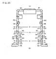
- Fig. 20(a) and Fig. 20(b) are exploded views showing a handle arm and a supporting frame of a circuit breaker according to an eleventh embodiment of the invention.
- Fig. 20(a) is a front view showing the handle arm of the circuit breaker of the tenth embodiment.
- Fig. 20(b) is a sectional front view showing the supporting frame of the circuit breaker of the eleventh embodiment.
- the circular rotation surfaces CR formed in the handle arm 42 of the second embodiment above are formed as circular rotation inclined surfaces CR1 and the circular support surfaces CS formed in the supporting frame 43 of the second embodiment above are formed as circular support inclined surfaces CS1.
- the handle arm 42 of the eleventh embodiment is configured in the same manner as the counterpart of the second embodiment above and the supporting frame 43 of the eleventh embodiment is configured in the same manner as the counterpart of the second embodiment above.
- the circuit breaker of the eleventh embodiment is configured in the same manner as the counterpart of the second embodiment above.
- the circular rotation inclined surfaces CR1 are formed to incline in a direction in which the cross bar 30 is extended in such a manner that the diameter of the rotation center portions RC on the side of the outer surfaces s22 becomes larger than the diameter on the side of the inner surfaces s12.
- the circular support inclined surfaces CS1 are formed to incline in a direction in which the cross bar 30 is extended correspondingly to the inclination of the circular rotation inclined surfaces CR1 in such a manner that the diameter of the rotation support portions RS on the side of the outer surfaces s41 becomes larger than the diameter on the side of the inner surfaces s31.
- the handle arm 42 is kept pushed in the direction of the supporting frame 43 by the main spring 48 and the pushing force in the direction of the supporting frame 43 generates a component force that forces the rotation center portions RC outward on the contact surfaces of the circular rotation inclined surfaces CR1 and the circular support inclined surfaces CS1. According to this component force, the outer surfaces s22 of the rotation center portions RC are pressed against the inner surfaces s32 of the thin walls TW and this configuration prevents a fall-off of the handle arm 42.
- circular rotation inclined surfaces CR1 and the circular support inclined surfaces CS1 of the tenth embodiment and the eleventh embodiment can be employed in the third through ninth embodiments instead of the circular rotation surfaces CR and the circular support surfaces CS.
- circuit breaker of the invention described above is used in an earth leakage breaker and a molded case circuit breaker.
Landscapes
- Breakers (AREA)
Applications Claiming Priority (1)
| Application Number | Priority Date | Filing Date | Title |
|---|---|---|---|
| JP2009138251A JP5297270B2 (ja) | 2009-06-09 | 2009-06-09 | 回路遮断器 |
Publications (2)
| Publication Number | Publication Date |
|---|---|
| EP2261945A1 true EP2261945A1 (fr) | 2010-12-15 |
| EP2261945B1 EP2261945B1 (fr) | 2012-03-28 |
Family
ID=42753438
Family Applications (1)
| Application Number | Title | Priority Date | Filing Date |
|---|---|---|---|
| EP09014246A Not-in-force EP2261945B1 (fr) | 2009-06-09 | 2009-11-13 | Disjoncteur |
Country Status (4)
| Country | Link |
|---|---|
| EP (1) | EP2261945B1 (fr) |
| JP (1) | JP5297270B2 (fr) |
| CN (1) | CN101923996B (fr) |
| AT (1) | ATE551712T1 (fr) |
Families Citing this family (3)
| Publication number | Priority date | Publication date | Assignee | Title |
|---|---|---|---|---|
| JP2012186065A (ja) * | 2011-03-07 | 2012-09-27 | Mitsubishi Electric Corp | 回路遮断器 |
| CN104025241B (zh) * | 2012-10-11 | 2015-12-09 | 三菱电机株式会社 | 电路断路器 |
| KR102342667B1 (ko) * | 2015-04-22 | 2021-12-23 | 엘에스일렉트릭(주) | 배선용 차단기 |
Citations (2)
| Publication number | Priority date | Publication date | Assignee | Title |
|---|---|---|---|---|
| JPH02104549U (fr) * | 1989-02-07 | 1990-08-20 | ||
| US5260533A (en) * | 1991-10-18 | 1993-11-09 | Westinghouse Electric Corp. | Molded case current limiting circuit breaker |
Family Cites Families (6)
| Publication number | Priority date | Publication date | Assignee | Title |
|---|---|---|---|---|
| CN1074852C (zh) * | 1996-03-15 | 2001-11-14 | 三菱电机株式会社 | 电路断路器 |
| JP4489930B2 (ja) * | 2000-11-13 | 2010-06-23 | 三菱電機株式会社 | 回路遮断器 |
| JP4186707B2 (ja) * | 2003-05-27 | 2008-11-26 | 松下電工株式会社 | 回路遮断器のハンドル支持装置 |
| JP4022524B2 (ja) * | 2004-03-16 | 2007-12-19 | 三菱電機株式会社 | 回路遮断器 |
| JP2007027148A (ja) * | 2006-11-06 | 2007-02-01 | Hitachi Industrial Equipment Systems Co Ltd | 回路遮断器 |
| JP4814848B2 (ja) * | 2007-08-09 | 2011-11-16 | 三菱電機株式会社 | 回路遮断器 |
-
2009
- 2009-06-09 JP JP2009138251A patent/JP5297270B2/ja active Active
- 2009-11-13 EP EP09014246A patent/EP2261945B1/fr not_active Not-in-force
- 2009-11-13 AT AT09014246T patent/ATE551712T1/de active
-
2010
- 2010-01-27 CN CN201010103288.7A patent/CN101923996B/zh active Active
Patent Citations (2)
| Publication number | Priority date | Publication date | Assignee | Title |
|---|---|---|---|---|
| JPH02104549U (fr) * | 1989-02-07 | 1990-08-20 | ||
| US5260533A (en) * | 1991-10-18 | 1993-11-09 | Westinghouse Electric Corp. | Molded case current limiting circuit breaker |
Also Published As
| Publication number | Publication date |
|---|---|
| CN101923996A (zh) | 2010-12-22 |
| EP2261945B1 (fr) | 2012-03-28 |
| ATE551712T1 (de) | 2012-04-15 |
| CN101923996B (zh) | 2013-06-19 |
| JP5297270B2 (ja) | 2013-09-25 |
| JP2010287331A (ja) | 2010-12-24 |
Similar Documents
| Publication | Publication Date | Title |
|---|---|---|
| EP3291274B1 (fr) | Mécanisme d'isolation par soudage par fusion pour mécanisme de fonctionnement de coupe-circuit | |
| US20100018846A1 (en) | Mold cased circuit breaker | |
| EP2261945B1 (fr) | Disjoncteur | |
| EP3291273B1 (fr) | Mécanisme de fonctionnement de disjoncteur | |
| KR101449884B1 (ko) | 회로 차단기 | |
| EP2161732A2 (fr) | Mécanisme de commutation pour disjoncteur de protection de moteur | |
| EP2107588B1 (fr) | Disjoncteur | |
| CN204614743U (zh) | 具有限位装置的跳扣组件 | |
| CN102122592B (zh) | 电路断路器 | |
| WO2012032381A2 (fr) | Agencement de boîtier de dérivation (tob) utilisé dans un système de distributeur à barres collectrices (bbt) | |
| WO2003015114A1 (fr) | Disjoncteur a air | |
| EP3291276B1 (fr) | Mécanisme de verrouillage secondaire pour mécanisme de fonctionnement de coupe-circuit | |
| CA2901430C (fr) | Appareil de poignee de solidarisation pour disjoncteurs unipolaires | |
| JPS6344936Y2 (fr) | ||
| CN102683125A (zh) | 电路断路器 | |
| JPH0547285A (ja) | 回路遮断器 | |
| JP3552867B2 (ja) | 回路遮断器 | |
| EP3316428B1 (fr) | Dispositif de déconnexion et appareillage de commutation à isolation gazeuse utilisant celui-ci | |
| JP2025183987A (ja) | 回路遮断器 | |
| JPH08167366A (ja) | 回路遮断器 | |
| JP2004006391A (ja) | 回路遮断器 | |
| JP2003086071A (ja) | 多極回路遮断器 | |
| JP2012109183A (ja) | 回路遮断器 | |
| JPS6386215A (ja) | 回路しや断器 |
Legal Events
| Date | Code | Title | Description |
|---|---|---|---|
| PUAI | Public reference made under article 153(3) epc to a published international application that has entered the european phase |
Free format text: ORIGINAL CODE: 0009012 |
|
| 17P | Request for examination filed |
Effective date: 20091113 |
|
| AK | Designated contracting states |
Kind code of ref document: A1 Designated state(s): AT BE BG CH CY CZ DE DK EE ES FI FR GB GR HR HU IE IS IT LI LT LU LV MC MK MT NL NO PL PT RO SE SI SK SM TR |
|
| AX | Request for extension of the european patent |
Extension state: AL BA RS |
|
| GRAP | Despatch of communication of intention to grant a patent |
Free format text: ORIGINAL CODE: EPIDOSNIGR1 |
|
| RIC1 | Information provided on ipc code assigned before grant |
Ipc: H01H 71/52 20060101AFI20110909BHEP |
|
| GRAS | Grant fee paid |
Free format text: ORIGINAL CODE: EPIDOSNIGR3 |
|
| GRAA | (expected) grant |
Free format text: ORIGINAL CODE: 0009210 |
|
| AK | Designated contracting states |
Kind code of ref document: B1 Designated state(s): AT BE BG CH CY CZ DE DK EE ES FI FR GB GR HR HU IE IS IT LI LT LU LV MC MK MT NL NO PL PT RO SE SI SK SM TR |
|
| REG | Reference to a national code |
Ref country code: GB Ref legal event code: FG4D |
|
| REG | Reference to a national code |
Ref country code: CH Ref legal event code: EP |
|
| REG | Reference to a national code |
Ref country code: AT Ref legal event code: REF Ref document number: 551712 Country of ref document: AT Kind code of ref document: T Effective date: 20120415 |
|
| REG | Reference to a national code |
Ref country code: IE Ref legal event code: FG4D |
|
| REG | Reference to a national code |
Ref country code: DE Ref legal event code: R096 Ref document number: 602009006074 Country of ref document: DE Effective date: 20120524 |
|
| REG | Reference to a national code |
Ref country code: NL Ref legal event code: VDEP Effective date: 20120328 |
|
| PG25 | Lapsed in a contracting state [announced via postgrant information from national office to epo] |
Ref country code: LT Free format text: LAPSE BECAUSE OF FAILURE TO SUBMIT A TRANSLATION OF THE DESCRIPTION OR TO PAY THE FEE WITHIN THE PRESCRIBED TIME-LIMIT Effective date: 20120328 Ref country code: HR Free format text: LAPSE BECAUSE OF FAILURE TO SUBMIT A TRANSLATION OF THE DESCRIPTION OR TO PAY THE FEE WITHIN THE PRESCRIBED TIME-LIMIT Effective date: 20120328 Ref country code: NO Free format text: LAPSE BECAUSE OF FAILURE TO SUBMIT A TRANSLATION OF THE DESCRIPTION OR TO PAY THE FEE WITHIN THE PRESCRIBED TIME-LIMIT Effective date: 20120628 |
|
| LTIE | Lt: invalidation of european patent or patent extension |
Effective date: 20120328 |
|
| PG25 | Lapsed in a contracting state [announced via postgrant information from national office to epo] |
Ref country code: LV Free format text: LAPSE BECAUSE OF FAILURE TO SUBMIT A TRANSLATION OF THE DESCRIPTION OR TO PAY THE FEE WITHIN THE PRESCRIBED TIME-LIMIT Effective date: 20120328 Ref country code: GR Free format text: LAPSE BECAUSE OF FAILURE TO SUBMIT A TRANSLATION OF THE DESCRIPTION OR TO PAY THE FEE WITHIN THE PRESCRIBED TIME-LIMIT Effective date: 20120629 Ref country code: FI Free format text: LAPSE BECAUSE OF FAILURE TO SUBMIT A TRANSLATION OF THE DESCRIPTION OR TO PAY THE FEE WITHIN THE PRESCRIBED TIME-LIMIT Effective date: 20120328 |
|
| REG | Reference to a national code |
Ref country code: AT Ref legal event code: MK05 Ref document number: 551712 Country of ref document: AT Kind code of ref document: T Effective date: 20120328 |
|
| PG25 | Lapsed in a contracting state [announced via postgrant information from national office to epo] |
Ref country code: CY Free format text: LAPSE BECAUSE OF FAILURE TO SUBMIT A TRANSLATION OF THE DESCRIPTION OR TO PAY THE FEE WITHIN THE PRESCRIBED TIME-LIMIT Effective date: 20120328 |
|
| PG25 | Lapsed in a contracting state [announced via postgrant information from national office to epo] |
Ref country code: SI Free format text: LAPSE BECAUSE OF FAILURE TO SUBMIT A TRANSLATION OF THE DESCRIPTION OR TO PAY THE FEE WITHIN THE PRESCRIBED TIME-LIMIT Effective date: 20120328 Ref country code: PL Free format text: LAPSE BECAUSE OF FAILURE TO SUBMIT A TRANSLATION OF THE DESCRIPTION OR TO PAY THE FEE WITHIN THE PRESCRIBED TIME-LIMIT Effective date: 20120328 Ref country code: SE Free format text: LAPSE BECAUSE OF FAILURE TO SUBMIT A TRANSLATION OF THE DESCRIPTION OR TO PAY THE FEE WITHIN THE PRESCRIBED TIME-LIMIT Effective date: 20120328 Ref country code: EE Free format text: LAPSE BECAUSE OF FAILURE TO SUBMIT A TRANSLATION OF THE DESCRIPTION OR TO PAY THE FEE WITHIN THE PRESCRIBED TIME-LIMIT Effective date: 20120328 Ref country code: BE Free format text: LAPSE BECAUSE OF FAILURE TO SUBMIT A TRANSLATION OF THE DESCRIPTION OR TO PAY THE FEE WITHIN THE PRESCRIBED TIME-LIMIT Effective date: 20120328 Ref country code: CZ Free format text: LAPSE BECAUSE OF FAILURE TO SUBMIT A TRANSLATION OF THE DESCRIPTION OR TO PAY THE FEE WITHIN THE PRESCRIBED TIME-LIMIT Effective date: 20120328 Ref country code: IS Free format text: LAPSE BECAUSE OF FAILURE TO SUBMIT A TRANSLATION OF THE DESCRIPTION OR TO PAY THE FEE WITHIN THE PRESCRIBED TIME-LIMIT Effective date: 20120728 Ref country code: RO Free format text: LAPSE BECAUSE OF FAILURE TO SUBMIT A TRANSLATION OF THE DESCRIPTION OR TO PAY THE FEE WITHIN THE PRESCRIBED TIME-LIMIT Effective date: 20120328 |
|
| PG25 | Lapsed in a contracting state [announced via postgrant information from national office to epo] |
Ref country code: SK Free format text: LAPSE BECAUSE OF FAILURE TO SUBMIT A TRANSLATION OF THE DESCRIPTION OR TO PAY THE FEE WITHIN THE PRESCRIBED TIME-LIMIT Effective date: 20120328 Ref country code: PT Free format text: LAPSE BECAUSE OF FAILURE TO SUBMIT A TRANSLATION OF THE DESCRIPTION OR TO PAY THE FEE WITHIN THE PRESCRIBED TIME-LIMIT Effective date: 20120730 |
|
| PG25 | Lapsed in a contracting state [announced via postgrant information from national office to epo] |
Ref country code: AT Free format text: LAPSE BECAUSE OF FAILURE TO SUBMIT A TRANSLATION OF THE DESCRIPTION OR TO PAY THE FEE WITHIN THE PRESCRIBED TIME-LIMIT Effective date: 20120328 Ref country code: NL Free format text: LAPSE BECAUSE OF FAILURE TO SUBMIT A TRANSLATION OF THE DESCRIPTION OR TO PAY THE FEE WITHIN THE PRESCRIBED TIME-LIMIT Effective date: 20120328 Ref country code: DK Free format text: LAPSE BECAUSE OF FAILURE TO SUBMIT A TRANSLATION OF THE DESCRIPTION OR TO PAY THE FEE WITHIN THE PRESCRIBED TIME-LIMIT Effective date: 20120328 |
|
| PLBE | No opposition filed within time limit |
Free format text: ORIGINAL CODE: 0009261 |
|
| STAA | Information on the status of an ep patent application or granted ep patent |
Free format text: STATUS: NO OPPOSITION FILED WITHIN TIME LIMIT |
|
| 26N | No opposition filed |
Effective date: 20130103 |
|
| REG | Reference to a national code |
Ref country code: DE Ref legal event code: R097 Ref document number: 602009006074 Country of ref document: DE Effective date: 20130103 |
|
| PG25 | Lapsed in a contracting state [announced via postgrant information from national office to epo] |
Ref country code: ES Free format text: LAPSE BECAUSE OF FAILURE TO SUBMIT A TRANSLATION OF THE DESCRIPTION OR TO PAY THE FEE WITHIN THE PRESCRIBED TIME-LIMIT Effective date: 20120709 |
|
| PG25 | Lapsed in a contracting state [announced via postgrant information from national office to epo] |
Ref country code: BG Free format text: LAPSE BECAUSE OF FAILURE TO SUBMIT A TRANSLATION OF THE DESCRIPTION OR TO PAY THE FEE WITHIN THE PRESCRIBED TIME-LIMIT Effective date: 20120628 |
|
| REG | Reference to a national code |
Ref country code: IE Ref legal event code: MM4A |
|
| PG25 | Lapsed in a contracting state [announced via postgrant information from national office to epo] |
Ref country code: IE Free format text: LAPSE BECAUSE OF NON-PAYMENT OF DUE FEES Effective date: 20121113 |
|
| PG25 | Lapsed in a contracting state [announced via postgrant information from national office to epo] |
Ref country code: MT Free format text: LAPSE BECAUSE OF FAILURE TO SUBMIT A TRANSLATION OF THE DESCRIPTION OR TO PAY THE FEE WITHIN THE PRESCRIBED TIME-LIMIT Effective date: 20120328 |
|
| PG25 | Lapsed in a contracting state [announced via postgrant information from national office to epo] |
Ref country code: TR Free format text: LAPSE BECAUSE OF FAILURE TO SUBMIT A TRANSLATION OF THE DESCRIPTION OR TO PAY THE FEE WITHIN THE PRESCRIBED TIME-LIMIT Effective date: 20120328 Ref country code: MC Free format text: LAPSE BECAUSE OF NON-PAYMENT OF DUE FEES Effective date: 20121130 |
|
| PG25 | Lapsed in a contracting state [announced via postgrant information from national office to epo] |
Ref country code: LU Free format text: LAPSE BECAUSE OF NON-PAYMENT OF DUE FEES Effective date: 20121113 Ref country code: SM Free format text: LAPSE BECAUSE OF FAILURE TO SUBMIT A TRANSLATION OF THE DESCRIPTION OR TO PAY THE FEE WITHIN THE PRESCRIBED TIME-LIMIT Effective date: 20120328 |
|
| REG | Reference to a national code |
Ref country code: CH Ref legal event code: PL |
|
| GBPC | Gb: european patent ceased through non-payment of renewal fee |
Effective date: 20131113 |
|
| PG25 | Lapsed in a contracting state [announced via postgrant information from national office to epo] |
Ref country code: LI Free format text: LAPSE BECAUSE OF NON-PAYMENT OF DUE FEES Effective date: 20131130 Ref country code: CH Free format text: LAPSE BECAUSE OF NON-PAYMENT OF DUE FEES Effective date: 20131130 Ref country code: HU Free format text: LAPSE BECAUSE OF FAILURE TO SUBMIT A TRANSLATION OF THE DESCRIPTION OR TO PAY THE FEE WITHIN THE PRESCRIBED TIME-LIMIT Effective date: 20091113 |
|
| REG | Reference to a national code |
Ref country code: DE Ref legal event code: R084 Ref document number: 602009006074 Country of ref document: DE |
|
| PG25 | Lapsed in a contracting state [announced via postgrant information from national office to epo] |
Ref country code: GB Free format text: LAPSE BECAUSE OF NON-PAYMENT OF DUE FEES Effective date: 20131113 |
|
| REG | Reference to a national code |
Ref country code: DE Ref legal event code: R084 Ref document number: 602009006074 Country of ref document: DE Effective date: 20141107 |
|
| PG25 | Lapsed in a contracting state [announced via postgrant information from national office to epo] |
Ref country code: MK Free format text: LAPSE BECAUSE OF FAILURE TO SUBMIT A TRANSLATION OF THE DESCRIPTION OR TO PAY THE FEE WITHIN THE PRESCRIBED TIME-LIMIT Effective date: 20120328 |
|
| REG | Reference to a national code |
Ref country code: FR Ref legal event code: PLFP Year of fee payment: 7 |
|
| REG | Reference to a national code |
Ref country code: FR Ref legal event code: PLFP Year of fee payment: 8 |
|
| REG | Reference to a national code |
Ref country code: FR Ref legal event code: PLFP Year of fee payment: 9 |
|
| REG | Reference to a national code |
Ref country code: FR Ref legal event code: PLFP Year of fee payment: 10 |
|
| PGFP | Annual fee paid to national office [announced via postgrant information from national office to epo] |
Ref country code: DE Payment date: 20201103 Year of fee payment: 12 Ref country code: IT Payment date: 20201013 Year of fee payment: 12 Ref country code: FR Payment date: 20201013 Year of fee payment: 12 |
|
| REG | Reference to a national code |
Ref country code: DE Ref legal event code: R119 Ref document number: 602009006074 Country of ref document: DE |
|
| PG25 | Lapsed in a contracting state [announced via postgrant information from national office to epo] |
Ref country code: DE Free format text: LAPSE BECAUSE OF NON-PAYMENT OF DUE FEES Effective date: 20220601 |
|
| PG25 | Lapsed in a contracting state [announced via postgrant information from national office to epo] |
Ref country code: FR Free format text: LAPSE BECAUSE OF NON-PAYMENT OF DUE FEES Effective date: 20211130 |
|
| PG25 | Lapsed in a contracting state [announced via postgrant information from national office to epo] |
Ref country code: IT Free format text: LAPSE BECAUSE OF NON-PAYMENT OF DUE FEES Effective date: 20211113 |