EP2262055A1 - Eingebaute zusammenklappbare Antenne für ein tragbares Endgerät - Google Patents
Eingebaute zusammenklappbare Antenne für ein tragbares Endgerät Download PDFInfo
- Publication number
- EP2262055A1 EP2262055A1 EP10165321A EP10165321A EP2262055A1 EP 2262055 A1 EP2262055 A1 EP 2262055A1 EP 10165321 A EP10165321 A EP 10165321A EP 10165321 A EP10165321 A EP 10165321A EP 2262055 A1 EP2262055 A1 EP 2262055A1
- Authority
- EP
- European Patent Office
- Prior art keywords
- antenna
- built
- conductive connection
- connection unit
- folder
- Prior art date
- Legal status (The legal status is an assumption and is not a legal conclusion. Google has not performed a legal analysis and makes no representation as to the accuracy of the status listed.)
- Withdrawn
Links
Images


Classifications
-
- H—ELECTRICITY
- H01—ELECTRIC ELEMENTS
- H01Q—ANTENNAS, i.e. RADIO AERIALS
- H01Q1/00—Details of, or arrangements associated with, antennas
- H01Q1/12—Supports; Mounting means
- H01Q1/22—Supports; Mounting means by structural association with other equipment or articles
- H01Q1/24—Supports; Mounting means by structural association with other equipment or articles with receiving set
- H01Q1/241—Supports; Mounting means by structural association with other equipment or articles with receiving set used in mobile communications, e.g. GSM
- H01Q1/242—Supports; Mounting means by structural association with other equipment or articles with receiving set used in mobile communications, e.g. GSM specially adapted for hand-held use
- H01Q1/243—Supports; Mounting means by structural association with other equipment or articles with receiving set used in mobile communications, e.g. GSM specially adapted for hand-held use with built-in antennas
-
- H—ELECTRICITY
- H01—ELECTRIC ELEMENTS
- H01Q—ANTENNAS, i.e. RADIO AERIALS
- H01Q1/00—Details of, or arrangements associated with, antennas
- H01Q1/12—Supports; Mounting means
- H01Q1/22—Supports; Mounting means by structural association with other equipment or articles
- H01Q1/24—Supports; Mounting means by structural association with other equipment or articles with receiving set
-
- H—ELECTRICITY
- H01—ELECTRIC ELEMENTS
- H01Q—ANTENNAS, i.e. RADIO AERIALS
- H01Q9/00—Electrically-short antennas having dimensions not more than twice the operating wavelength and consisting of conductive active radiating elements
- H01Q9/04—Resonant antennas
- H01Q9/16—Resonant antennas with feed intermediate between the extremities of the antenna, e.g. centre-fed dipole
-
- H—ELECTRICITY
- H04—ELECTRIC COMMUNICATION TECHNIQUE
- H04B—TRANSMISSION
- H04B1/00—Details of transmission systems, not covered by a single one of groups H04B3/00 - H04B13/00; Details of transmission systems not characterised by the medium used for transmission
- H04B1/38—Transceivers, i.e. devices in which transmitter and receiver form a structural unit and in which at least one part is used for functions of transmitting and receiving
Definitions
- the present invention relates generally to a folder type portable terminal, and in particular, to a folder type portable terminal having a built-in antenna capable of receiving a broadcasting signal of a low frequency band using only a built-in antenna without the need of an external antenna.
- portable terminals may be classified according to an opening and closing operation of a sub-body.
- Various types of terminals such as a bar type terminal, a flip type terminal, a folder type terminal, a slide type terminal, a pop-up type terminal, and a slide and rotation type terminal are available to meet the preferences of various consumers.
- a speaker that realizes melodies having various harmonizing voices, MP3 player, and a color display device having millions of pixel may be installed in the terminals.
- digital broadcasting services such as game contents, digital multi-media broadcasting (DMB), digital video broadcasting-handheld (DVB-H), integrated services digital broadcasting-terrestrial ((ISDB-T) using the display device may be provided to the terminal.
- DMB digital multi-media broadcasting
- DVD-H digital video broadcasting-handheld
- ISDB-T integrated services digital broadcasting-terrestrial
- a separate broadcasting antenna for receiving and transmitting external signals is used.
- the DBM is operated at a frequency of about 180 MHz to about 210 MHz
- the DVB-H or the ISDB-T is operated at a frequency of about 470 MHz to about 862 MHz.
- a relatively large antenna must be used.
- a detachable antenna has been provided to a terminal buyer to receive the DVB-H or the ISDB-T.
- a retractable antenna which is disposed inside the terminal is available for receiving the broadcasting signals.
- the retractable antenna includes a helical antenna fixed to the terminal or a whip antenna disposed inside a general bushing to protrude by a predetermined length.
- the retractable antenna occupies a space for installing the antenna within the terminal, it is drawbacks when making the terminal slimmer. Also, since the whip antenna protrudes from the terminal, the whip antenna may be damaged during the usage.
- An exemplary aspect of the present invention is to substantially solve at least the above problems and/or disadvantages and to provide at least the advantages below. Accordingly, an object of the present invention is to provide a built-in antenna for a folder type portable terminal capable ofreceiving broadcasting signals without providing a separate antenna installed inside thereof.
- Another exemplary aspect of the present invention is to provide a built-in antenna for a folder type portable terminal, in which an antenna installation space is minimized to realize a slimmer terminal.
- Another exemplary aspect of the present invention is to provide a built-in antenna for a folder type portable terminal, which prevents a malfunction of the terminal due to damage of the antenna.
- Another exemplary aspect of the present invention is to provide a built-in antenna for a folder type portable terminal, in which a separate broadcasting antenna is not required because the entire terminal serves as an antenna radiator.
- a built-in antenna for a folder type portable terminal includes: a main body including a main board; an openable folder rotated at a predetermined angle with respect to the main body; a metallic hinge module rotating the folder on the main body to provide an opening and closing sensation of the folder; a conductor electrically connected to the metallic hinge module, the conductor being disposed inside the folder; and at least one conductive connection unit electrically connected to a broadcasting signal line of the main board, wherein one conductive connection unit is electrically coupled to the hinge module through a non-contact coupling.
- FIG. 1 is a perspective view of a folder type portable terminal to which a built-in antenna is applied according to an embodiment of the present invention
- FIG. 2 is a schematic view of a state in which a built-in antenna is installed according to an embodiment of the present invention.
- a folder type portable terminal 100 includes a main body 110 and a folder 120 capable of being opened and closed at a predetermined angle with respect to the main body 110.
- a plurality of key button assemblies 111 is disposed on the main body 110.
- a 3 ⁇ 4 keypad assembly and a navigation keypad assembly may be disposed on the main body 110.
- a microphone 112 is disposed below the key pad assemblies 111.
- a display device 130 having a predetermined size may be disposed on the folder 120.
- a speaker 121 is disposed above the display device 130.
- the folder 120 is rotatably folded on to the main body 110.
- a center hinge arm 123 is disposed on the folder 120.
- Side hinge arms 113 facing each other are disposed on both lateral surfaces of the main body 110.
- a predetermined hinge module (see reference numeral 150 of FIG. 2 ) is received into the center hinge arm 123.
- the hinge module 150 is partially fixed to the side hinge arms 113 and communicates with the side hinge arms 113 to provide an opening and closing feeling of the folder 120 to a user.
- the hinge module 150 induces a change of direction in an opening and closing direction of the folder 120 at a certain time point during an operation of the folder 120.
- the present invention is not limited thereto. If the center hinge arm 123 on which the hinge module 150 is disposed is disposed on the main body 110, the corresponding side hinge arms 113 may be disposed on the folder 120.
- the hinge module 150 may be disposed on the above-described center hinge arm 123.
- the center hinge arm 123 and the side hinge arms 113 may be formed of a synthetic resin material, and the hinge module 150 may be formed of a metal material.
- the entire terminal serves as one large dipole antenna radiator.
- the hinge module 150 may be connected to a feedline of a broadcasting signal line constituting the main board 140.
- a conductor included in the folder 120 may be used as an antenna radiator.
- a ground of the main board 140 may serve as a ground structure.
- a reinforcement plate 132 which serves as a conductor of the folder 120 and is a metal plate for protecting an LCD panel 131 of an LCD module 130, may be electrically connected to the metallic hinge module 150 by a conductive member 133.
- Various well-known conductors such as a flexible printed circuit (FPC), a metal plate, and a metal tape may be used as the conductive member 133.
- the main board 140 includes a first conductive connection unit 151 electrically connected to the hinge module 150 and a second conductive connection unit 141 having one end spaced a predetermined distance from the first conductive connection unit 151 and the other end electrically connected the signal line of the main board 140.
- first conductive connection unit 151 and the second conductive connection unit 141 are spaced from each other, a space in which the first conductive connection unit 151 overlaps with the second conductive connection unit 141 by a predetermined width may serve as a dielectric to perform an electrical connection operation.
- the first and second conductive connection units 151 and 141 may be formed of conductive materials, respectively.
- FIG. 3 is a schematic view illustrating an install state of a built-in antenna according to an embodiment of the present invention and relates to FIG. 2 .
- the metallic hinge module 150 is built in the center hinge arm 123 of the folder 120.
- the hinge module 150 is electrically connected to the metallic reinforcement plate 132 of the LCD module 130 by the predetermined conductive member 133.
- the first conductive connection unit 151 has one end electrically connected to the hinge module 150 and the other end withdrawn toward the inside of the main body 110 by a predetermined length.
- the first conductive connection unit 151 may be a plate type connection unit having a predetermined area.
- the second conductive connection unit 141 has one end that overlaps with the first conductive connection unit 151, but does not contact the first conductive connection unit 151 and the other end electrically connected to the broadcasting signal line 142 of the main board 140.
- the second conductive connection unit 141 may be also a plate type connection unit having a predetermined area. Portions of the first and second conductive connection units 151 and 141, which overlap with each other, may have the same area.
- the hinge module 150 and the reinforcement plate 132 for the LCD module may be connected to the signal line 142 of the main board 140 and simultaneously connected to the ground.
- At least one matching circuit may be disposed on the signal line 142 to aid the formation of a desired antenna pattern.
- FIG. 4 is a schematic view illustrating an installation relationship of a built-in antenna according to another embodiment of the present invention.
- the built-in antenna of FIG. 4 has the same component as that of FIG. 3 except that the first conductive connection unit 151 is formed as one connection unit.
- the one connection unit is called a third connection unit 152.
- the third connection unit 152 has one end connected to the signal line 142 of the main board 140 and the other end having the same configuration as that of the hinge module 150 and disposed close to an outer circumference of the hinge module 150.
- the third connection unit 152 may be also a plate type connection unit.
- the first, second, and third connection units 151, 141, and 152 may be disposed on the main body 110 through various methods. For example, a metal plate having a predetermined area may be attached to an inner surface of a frame of the main board 140 or insert-molded when the frame is injected.
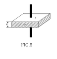
- FIG. 5 is a schematic view for illustrating the capacitance calculation of a dielectric between two metal plates according to an embodiment of the present invention.
- the electrical connection between the first conductive connection unit and the second conductive connection unit or the electrical connection between the hinge module and the third connection unit may be described with reference to FIG. 3 and calculated using Equation 1.
- C ⁇ ⁇ S d
- S is a area of the respective plates
- d is a distance between the plates.
- a desired capacitance C may be calculated considering that capacitance C is in inverse proportion to the distance d between the plates and in proportion to the area S of the respective plates.
- connection units are built in the case frame of the main board using the insert-molding
- 5 pF is equal to [3 ⁇ 80854 ⁇ 10 -12 ) ⁇ S]/1mm by Equation 1.
- the area S of the respective plates is about 0.1888 mm 2 and has a general square shape, an area of about 1.3 cm ⁇ 1.3 cm is required.
- a terminal manufacturer may calculate and selectively apply the desired capacitance in consideration of the first, second, and third connection units. Also, according to the above-described components, since the main board and the folder, which are relatively and frequently rotated with respect to each other, are electrically connected to each other in a non-contact state, a malfunction of the terminal due to the disconnection may be prevented even though the terminal is operated for a long time.
- Table 1 shows peak sensitivities of the built-in antenna according to the first and second embodiments of the present invention and an existing retractable external antenna.
- PEAK sensitivity [dBm. CO-Polarization] 13 Ch. 21 Ch. 27 Ch. 40 Ch. 53 Ch.
- An embodiment -46 -50 -51 -53 -51 Another embodiment -44 -51 -52 -50 -50 Existing external antenna -48 -53 -54 -52 -51
- Radiated performance measurement over an actual available frequency band 13 Ch.: 473 MHz/ 53 Ch.: 713 MHz
- radiated performance was measured over a range of from 13 Ch (473 MHz) to 53 Ch (713 MHz) that is an actual available frequency band. It is observed that the built-in broadcasting antenna according to the present invention has performance similar to that of an existing external antenna.
- the built-in antenna according to the present invention maximally uses existing components, a separate space in which the antenna radiator is mounted as in the prior art is not needed. Thus, the terminal may be far slimmer when the teachings of present invention is applied.
Landscapes
- Engineering & Computer Science (AREA)
- Computer Networks & Wireless Communication (AREA)
- Signal Processing (AREA)
- Support Of Aerials (AREA)
- Telephone Set Structure (AREA)
- Structure Of Receivers (AREA)
- Input Circuits Of Receivers And Coupling Of Receivers And Audio Equipment (AREA)
Applications Claiming Priority (1)
| Application Number | Priority Date | Filing Date | Title |
|---|---|---|---|
| KR1020090052130A KR20100133536A (ko) | 2009-06-12 | 2009-06-12 | 폴더 타입 휴대용 단말기의 내장형 안테나 장치 |
Publications (1)
| Publication Number | Publication Date |
|---|---|
| EP2262055A1 true EP2262055A1 (de) | 2010-12-15 |
Family
ID=42555433
Family Applications (1)
| Application Number | Title | Priority Date | Filing Date |
|---|---|---|---|
| EP10165321A Withdrawn EP2262055A1 (de) | 2009-06-12 | 2010-06-09 | Eingebaute zusammenklappbare Antenne für ein tragbares Endgerät |
Country Status (4)
| Country | Link |
|---|---|
| US (1) | US20100317415A1 (de) |
| EP (1) | EP2262055A1 (de) |
| JP (1) | JP2010288281A (de) |
| KR (1) | KR20100133536A (de) |
Cited By (4)
| Publication number | Priority date | Publication date | Assignee | Title |
|---|---|---|---|---|
| CN105939408A (zh) * | 2016-05-30 | 2016-09-14 | 芜湖辉灿电子科技有限公司 | 一种增强通讯性能的手机 |
| TWI568075B (zh) * | 2015-09-08 | 2017-01-21 | Hongbo Wireless Communication Technology Co Ltd | Electronic devices and their composite antennas |
| CN109216865A (zh) * | 2018-08-29 | 2019-01-15 | Oppo广东移动通信有限公司 | 电子设备 |
| CN109244675A (zh) * | 2018-08-29 | 2019-01-18 | Oppo广东移动通信有限公司 | 壳体组件及电子设备 |
Families Citing this family (2)
| Publication number | Priority date | Publication date | Assignee | Title |
|---|---|---|---|---|
| KR102367678B1 (ko) * | 2015-11-19 | 2022-02-28 | 삼성전자주식회사 | 힌지 장치를 구비하는 전자 장치 |
| KR102560096B1 (ko) | 2018-10-24 | 2023-07-26 | 삼성전자주식회사 | 안테나 및 그것을 포함하는 전자 장치 |
Citations (4)
| Publication number | Priority date | Publication date | Assignee | Title |
|---|---|---|---|---|
| EP1538694A1 (de) * | 2002-07-19 | 2005-06-08 | Matsushita Electric Industrial Co., Ltd. | Tragbare drahtlose maschine |
| EP1724938A1 (de) * | 2005-05-19 | 2006-11-22 | Sony Ericsson Mobile Communications AB | Antenne für ein Mobil-Klapptelefon |
| EP1739785A1 (de) * | 2004-10-28 | 2007-01-03 | Matsushita Electric Industries Co., Ltd. | Faltbares tragbares radio |
| EP1962372A1 (de) * | 2006-02-17 | 2008-08-27 | BenQ Mobile GmbH & Co. oHG | Kleine, Breitbandigeantenne mit Induktive Chassiskopplung |
Family Cites Families (17)
| Publication number | Priority date | Publication date | Assignee | Title |
|---|---|---|---|---|
| US20030129950A1 (en) * | 2002-01-10 | 2003-07-10 | Min-Woo Kwak | Antenna of wireless phone |
| US8060167B2 (en) * | 2002-07-19 | 2011-11-15 | Panasonic Corporation | Portable wireless machine |
| AU2003289883A1 (en) * | 2002-11-26 | 2004-06-18 | Sony Ericsson Mobile Communications Ab | Antenna for portable communication device equipped with a hinge |
| EP1445821A1 (de) * | 2003-02-06 | 2004-08-11 | Matsushita Electric Industrial Co., Ltd. | Tragbares Funkkommunikationsgerät mit einem Auslegerteil |
| WO2005053089A1 (ja) * | 2003-11-26 | 2005-06-09 | Sharp Kabushiki Kaisha | 携帯無線機 |
| JP4358084B2 (ja) * | 2004-07-12 | 2009-11-04 | パナソニック株式会社 | 折畳式携帯無線機 |
| WO2006046714A1 (ja) * | 2004-10-28 | 2006-05-04 | Matsushita Electric Industrial Co., Ltd. | 放送用受信機付き携帯電話 |
| JP4691958B2 (ja) * | 2004-10-29 | 2011-06-01 | 日本電気株式会社 | 携帯無線端末 |
| JP2006129386A (ja) * | 2004-11-01 | 2006-05-18 | Fujitsu Ltd | アンテナ装置及び無線通信装置 |
| JP4661180B2 (ja) * | 2004-11-19 | 2011-03-30 | 日本電気株式会社 | 携帯無線端末及びアンテナ電流のアース方法 |
| KR100768505B1 (ko) * | 2006-06-14 | 2007-10-19 | 삼성전자주식회사 | 저주파 대역 방송신호의 수신이 가능한 내장형 다이폴안테나 |
| KR100822475B1 (ko) * | 2006-10-19 | 2008-04-16 | 삼성전자주식회사 | 저주파대역 무선신호의 송수신이 가능한 능동형 안테나 및이를 구비한 이동통신 단말기 |
| KR101335824B1 (ko) * | 2007-04-19 | 2013-12-03 | 엘지전자 주식회사 | 이동단말기 |
| US20090027561A1 (en) * | 2007-07-24 | 2009-01-29 | Broadcom Corporation | Mobile tv system with usb interface |
| JP5070978B2 (ja) * | 2007-07-31 | 2012-11-14 | 日立電線株式会社 | アンテナおよびそれを備えた携帯端末ならびに電気機器 |
| WO2009037523A2 (en) * | 2007-09-20 | 2009-03-26 | Nokia Corporation | An antenna arrangement, a method for manufacturing an antenna arrangement and a printed wiring board for use in an antenna arrangement |
| JP5121649B2 (ja) * | 2008-09-26 | 2013-01-16 | 株式会社東芝 | 無線装置 |
-
2009
- 2009-06-12 KR KR1020090052130A patent/KR20100133536A/ko not_active Withdrawn
-
2010
- 2010-06-07 US US12/794,830 patent/US20100317415A1/en not_active Abandoned
- 2010-06-09 EP EP10165321A patent/EP2262055A1/de not_active Withdrawn
- 2010-06-11 JP JP2010134454A patent/JP2010288281A/ja active Pending
Patent Citations (4)
| Publication number | Priority date | Publication date | Assignee | Title |
|---|---|---|---|---|
| EP1538694A1 (de) * | 2002-07-19 | 2005-06-08 | Matsushita Electric Industrial Co., Ltd. | Tragbare drahtlose maschine |
| EP1739785A1 (de) * | 2004-10-28 | 2007-01-03 | Matsushita Electric Industries Co., Ltd. | Faltbares tragbares radio |
| EP1724938A1 (de) * | 2005-05-19 | 2006-11-22 | Sony Ericsson Mobile Communications AB | Antenne für ein Mobil-Klapptelefon |
| EP1962372A1 (de) * | 2006-02-17 | 2008-08-27 | BenQ Mobile GmbH & Co. oHG | Kleine, Breitbandigeantenne mit Induktive Chassiskopplung |
Cited By (5)
| Publication number | Priority date | Publication date | Assignee | Title |
|---|---|---|---|---|
| TWI568075B (zh) * | 2015-09-08 | 2017-01-21 | Hongbo Wireless Communication Technology Co Ltd | Electronic devices and their composite antennas |
| CN105939408A (zh) * | 2016-05-30 | 2016-09-14 | 芜湖辉灿电子科技有限公司 | 一种增强通讯性能的手机 |
| CN109216865A (zh) * | 2018-08-29 | 2019-01-15 | Oppo广东移动通信有限公司 | 电子设备 |
| CN109244675A (zh) * | 2018-08-29 | 2019-01-18 | Oppo广东移动通信有限公司 | 壳体组件及电子设备 |
| CN109216865B (zh) * | 2018-08-29 | 2021-03-02 | Oppo广东移动通信有限公司 | 电子设备 |
Also Published As
| Publication number | Publication date |
|---|---|
| KR20100133536A (ko) | 2010-12-22 |
| US20100317415A1 (en) | 2010-12-16 |
| JP2010288281A (ja) | 2010-12-24 |
Similar Documents
| Publication | Publication Date | Title |
|---|---|---|
| US8174452B2 (en) | Cavity antenna for wireless electronic devices | |
| US7456794B2 (en) | Foldable portable radio | |
| TWI515958B (zh) | 帶有具鉸鏈外殼之電子裝置中的天線結構 | |
| JP3596774B1 (ja) | 携帯無線機 | |
| US7787915B2 (en) | Folding type portable wireless unit | |
| EP1881681B1 (de) | Mobiltelefon | |
| EP2262055A1 (de) | Eingebaute zusammenklappbare Antenne für ein tragbares Endgerät | |
| EP1482646B1 (de) | Tragbares Endgerät mit Abstimmeinrichtung zum Ändern der Strahlungscharakteristik | |
| US7173568B2 (en) | Antenna device and radio communication device | |
| KR100846343B1 (ko) | 휴대용 무선단말기의 내장형 안테나 장치 | |
| US20040217904A1 (en) | Computer with an embedded antenna | |
| US7602344B2 (en) | Portable terminal with variable ground unit | |
| KR20030019636A (ko) | 휴대무선 단말장치 | |
| KR100696886B1 (ko) | 휴대용 무선단말기의 내장형 안테나 장치 | |
| US7271771B2 (en) | Film antenna | |
| US20080261667A1 (en) | Mobile terminal having an improved internal antenna | |
| JP4600571B2 (ja) | 無線通信機 | |
| US6362786B1 (en) | Patch antenna utilized in conjunction with an electronic apparatus | |
| US8660620B2 (en) | Antenna built in mobile terminal | |
| US7825862B2 (en) | Antenna device with surface antenna pattern integrally coated casing of electronic device | |
| EP1662607A1 (de) | Tragbares drahtloses Gerät mit Leiter zur Verbesserung der Antenneneigenschaften | |
| CN102082849B (zh) | 一种翻盖手机内pcb板接地结构 | |
| US20070229373A1 (en) | Folding Portable Wireless Apparatus | |
| EP1646108B1 (de) | Antennenmodul für ein tragbares drahtloses Endgerät | |
| US20120273259A1 (en) | Signal transmission devices and portable radio communication devices comprising such signal transmission devices |
Legal Events
| Date | Code | Title | Description |
|---|---|---|---|
| PUAI | Public reference made under article 153(3) epc to a published international application that has entered the european phase |
Free format text: ORIGINAL CODE: 0009012 |
|
| AK | Designated contracting states |
Kind code of ref document: A1 Designated state(s): AL AT BE BG CH CY CZ DE DK EE ES FI FR GB GR HR HU IE IS IT LI LT LU LV MC MK MT NL NO PL PT RO SE SI SK SM TR |
|
| AX | Request for extension of the european patent |
Extension state: BA ME RS |
|
| 17P | Request for examination filed |
Effective date: 20110615 |
|
| RAP1 | Party data changed (applicant data changed or rights of an application transferred) |
Owner name: SAMSUNG ELECTRONICS CO., LTD. |
|
| STAA | Information on the status of an ep patent application or granted ep patent |
Free format text: STATUS: THE APPLICATION IS DEEMED TO BE WITHDRAWN |
|
| 18D | Application deemed to be withdrawn |
Effective date: 20140102 |