EP2262092B1 - Umrichtersteuerungsvorrichtung und Klimaanlage und diese Vorrichtung benutzende Waschmaschine - Google Patents
Umrichtersteuerungsvorrichtung und Klimaanlage und diese Vorrichtung benutzende Waschmaschine Download PDFInfo
- Publication number
- EP2262092B1 EP2262092B1 EP10006087A EP10006087A EP2262092B1 EP 2262092 B1 EP2262092 B1 EP 2262092B1 EP 10006087 A EP10006087 A EP 10006087A EP 10006087 A EP10006087 A EP 10006087A EP 2262092 B1 EP2262092 B1 EP 2262092B1
- Authority
- EP
- European Patent Office
- Prior art keywords
- current
- motor
- inverter
- phase currents
- voltage
- Prior art date
- Legal status (The legal status is an assumption and is not a legal conclusion. Google has not performed a legal analysis and makes no representation as to the accuracy of the status listed.)
- Not-in-force
Links
- 238000001914 filtration Methods 0.000 claims abstract description 15
- 238000001514 detection method Methods 0.000 claims description 27
- 238000004519 manufacturing process Methods 0.000 abstract description 2
- 238000010586 diagram Methods 0.000 description 29
- 238000000034 method Methods 0.000 description 29
- 230000014509 gene expression Effects 0.000 description 22
- 238000005070 sampling Methods 0.000 description 14
- 238000006243 chemical reaction Methods 0.000 description 7
- 239000007787 solid Substances 0.000 description 6
- 230000003247 decreasing effect Effects 0.000 description 5
- 230000008569 process Effects 0.000 description 5
- 238000013459 approach Methods 0.000 description 4
- 230000018044 dehydration Effects 0.000 description 4
- 238000006297 dehydration reaction Methods 0.000 description 4
- 241000826860 Trapezium Species 0.000 description 3
- 230000008859 change Effects 0.000 description 3
- 238000007796 conventional method Methods 0.000 description 3
- 238000012545 processing Methods 0.000 description 3
- 239000003507 refrigerant Substances 0.000 description 3
- 230000003313 weakening effect Effects 0.000 description 3
- 230000015556 catabolic process Effects 0.000 description 2
- 238000006731 degradation reaction Methods 0.000 description 2
- 230000000593 degrading effect Effects 0.000 description 2
- 230000004044 response Effects 0.000 description 2
- 230000001360 synchronised effect Effects 0.000 description 2
- 238000012935 Averaging Methods 0.000 description 1
- 235000008733 Citrus aurantifolia Nutrition 0.000 description 1
- 235000011941 Tilia x europaea Nutrition 0.000 description 1
- 239000003990 capacitor Substances 0.000 description 1
- 239000000969 carrier Substances 0.000 description 1
- 230000001419 dependent effect Effects 0.000 description 1
- 238000013461 design Methods 0.000 description 1
- 230000004907 flux Effects 0.000 description 1
- 239000004571 lime Substances 0.000 description 1
- 230000004048 modification Effects 0.000 description 1
- 238000012986 modification Methods 0.000 description 1
- 229920006395 saturated elastomer Polymers 0.000 description 1
- 238000004904 shortening Methods 0.000 description 1
- 230000001131 transforming effect Effects 0.000 description 1
- 238000005406 washing Methods 0.000 description 1
- XLYOFNOQVPJJNP-UHFFFAOYSA-N water Substances O XLYOFNOQVPJJNP-UHFFFAOYSA-N 0.000 description 1
Images


Classifications
-
- H—ELECTRICITY
- H02—GENERATION; CONVERSION OR DISTRIBUTION OF ELECTRIC POWER
- H02P—CONTROL OR REGULATION OF ELECTRIC MOTORS, ELECTRIC GENERATORS OR DYNAMO-ELECTRIC CONVERTERS; CONTROLLING TRANSFORMERS, REACTORS OR CHOKE COILS
- H02P27/00—Arrangements or methods for the control of AC motors characterised by the kind of supply voltage
- H02P27/04—Arrangements or methods for the control of AC motors characterised by the kind of supply voltage using variable-frequency supply voltage, e.g. inverter or converter supply voltage
- H02P27/06—Arrangements or methods for the control of AC motors characterised by the kind of supply voltage using variable-frequency supply voltage, e.g. inverter or converter supply voltage using DC to AC converters or inverters
-
- H—ELECTRICITY
- H02—GENERATION; CONVERSION OR DISTRIBUTION OF ELECTRIC POWER
- H02P—CONTROL OR REGULATION OF ELECTRIC MOTORS, ELECTRIC GENERATORS OR DYNAMO-ELECTRIC CONVERTERS; CONTROLLING TRANSFORMERS, REACTORS OR CHOKE COILS
- H02P23/00—Arrangements or methods for the control of AC motors characterised by a control method other than vector control
- H02P23/0004—Control strategies in general, e.g. linear type, e.g. P, PI, PID, using robust control
-
- H—ELECTRICITY
- H02—GENERATION; CONVERSION OR DISTRIBUTION OF ELECTRIC POWER
- H02P—CONTROL OR REGULATION OF ELECTRIC MOTORS, ELECTRIC GENERATORS OR DYNAMO-ELECTRIC CONVERTERS; CONTROLLING TRANSFORMERS, REACTORS OR CHOKE COILS
- H02P27/00—Arrangements or methods for the control of AC motors characterised by the kind of supply voltage
- H02P27/04—Arrangements or methods for the control of AC motors characterised by the kind of supply voltage using variable-frequency supply voltage, e.g. inverter or converter supply voltage
- H02P27/06—Arrangements or methods for the control of AC motors characterised by the kind of supply voltage using variable-frequency supply voltage, e.g. inverter or converter supply voltage using DC to AC converters or inverters
- H02P27/08—Arrangements or methods for the control of AC motors characterised by the kind of supply voltage using variable-frequency supply voltage, e.g. inverter or converter supply voltage using DC to AC converters or inverters with pulse width modulation
-
- H—ELECTRICITY
- H02—GENERATION; CONVERSION OR DISTRIBUTION OF ELECTRIC POWER
- H02M—APPARATUS FOR CONVERSION BETWEEN AC AND AC, BETWEEN AC AND DC, OR BETWEEN DC AND DC, AND FOR USE WITH MAINS OR SIMILAR POWER SUPPLY SYSTEMS; CONVERSION OF DC OR AC INPUT POWER INTO SURGE OUTPUT POWER; CONTROL OR REGULATION THEREOF
- H02M1/00—Details of apparatus for conversion
- H02M1/0003—Details of control, feedback or regulation circuits
- H02M1/0009—Devices or circuits for detecting current in a converter
-
- H—ELECTRICITY
- H02—GENERATION; CONVERSION OR DISTRIBUTION OF ELECTRIC POWER
- H02M—APPARATUS FOR CONVERSION BETWEEN AC AND AC, BETWEEN AC AND DC, OR BETWEEN DC AND DC, AND FOR USE WITH MAINS OR SIMILAR POWER SUPPLY SYSTEMS; CONVERSION OF DC OR AC INPUT POWER INTO SURGE OUTPUT POWER; CONTROL OR REGULATION THEREOF
- H02M7/00—Conversion of AC power input into DC power output; Conversion of DC power input into AC power output
- H02M7/42—Conversion of DC power input into AC power output without possibility of reversal
- H02M7/44—Conversion of DC power input into AC power output without possibility of reversal by static converters
- H02M7/48—Conversion of DC power input into AC power output without possibility of reversal by static converters using discharge tubes with control electrode or semiconductor devices with control electrode
- H02M7/53—Conversion of DC power input into AC power output without possibility of reversal by static converters using discharge tubes with control electrode or semiconductor devices with control electrode using devices of a triode or transistor type requiring continuous application of a control signal
- H02M7/537—Conversion of DC power input into AC power output without possibility of reversal by static converters using discharge tubes with control electrode or semiconductor devices with control electrode using devices of a triode or transistor type requiring continuous application of a control signal using semiconductor devices only, e.g. single switched pulse inverters
- H02M7/5387—Conversion of DC power input into AC power output without possibility of reversal by static converters using discharge tubes with control electrode or semiconductor devices with control electrode using devices of a triode or transistor type requiring continuous application of a control signal using semiconductor devices only, e.g. single switched pulse inverters in a bridge configuration
- H02M7/53871—Conversion of DC power input into AC power output without possibility of reversal by static converters using discharge tubes with control electrode or semiconductor devices with control electrode using devices of a triode or transistor type requiring continuous application of a control signal using semiconductor devices only, e.g. single switched pulse inverters in a bridge configuration with automatic control of output voltage or current
- H02M7/53875—Conversion of DC power input into AC power output without possibility of reversal by static converters using discharge tubes with control electrode or semiconductor devices with control electrode using devices of a triode or transistor type requiring continuous application of a control signal using semiconductor devices only, e.g. single switched pulse inverters in a bridge configuration with automatic control of output voltage or current with analogue control of three-phase output
Definitions
- This invention relates to an apparatus for controlling an inverter, and more specifically to a method of detecting the output current of an inverter and also a technique for detecting the output currents (phase-currents) flowing through the DC bus.
- An inverter control apparatus incorporating therein a current reproduction unit as defined in the preamble portion of patent claim 1 is known from US 2008/079377 A1
- a permanent magnet motor is usually used to be driven by the apparatus.
- An example of an attempt to further improve the efficiency is the design of an electric motor which develops a high efficiency in the normal operation (in the low rotational speed range) of an air conditioner or a washer.
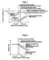
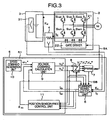
- Figs. 1 and 2 graphically illustrate the characteristics of the electric motor being driven.
- Fig. 1 graphically shows the relationship between the rotational speed, i.e. a number of revolutions per minute or rpm for short, of the motor and the voltage applied to the motor from the inverter, and between the rpm and the current to be outputted from the inverter.
- Fig. 2 graphically shows the relationship between the rpm and the output torque, of the motor.
- a permanent magnet motor induces back emf, i.e. back electromotive force, whose magnitude is proportional to its rpm
- the voltage developed across the inverter increases in proportion to the rpm, as represented with a solid curve (designating the inverter voltage) in Fig. 1
- the motor can generate a constant torque as shown in Fig. 2 .
- rpm of the motor exceeds N1
- an amount of the counter emf induced across the motor exceeds the voltage Vo that can be supplied from the inverter.
- the region of rpm equal to or greater than N1 is termed "voltage saturation range".
- an electric motor designed to achieve a high efficiency exhibits a low value of Ni that is the beginning point of the voltage saturation range.
- the high-efficiency motor can be said to have a narrow range of normal operation and a wide range of voltage saturation.
- the "field-weakening control" is used in the voltage saturation range in excess of N1 in Fig. 1 .
- the induced emf is apparently reduced by causing reactive current to flow through the motor in the range of high-speed rotation equal to or greater than N1. Accordingly, the range of rpm's attainable can be expanded.
- the inverter output current increases for rpm's exceeding Ni so that the efficiency of the electric motor driving apparatus as whole is made undesirably lowered.
- the output torque that can be developed is also decreased with the increase with rpm when rpm exceeds N1.
- the over-modulated PWM control has been proposed as a method for increasing the voltage that can be supplied from the inverter.
- JP 02-197295 A discloses such a control method as dispenses with a phase-current sensor, according to which the instantaneous phase currents of the motor are detected on the basis of the current flowing through the DC bus in the circuit of the inverter that is driving the motor and on the basis of the switching status of the inverter, so that the phase currents of the motor are reproduced.
- JP 2003-219678 A discloses a control method, according to which, on the basis of the average current supplied through the DC bus to the inverter and the DC voltage applied to the inverter, the DC current flowing into the motor is derived and the motor torque current is also detected.
- the current reproduction fails if only the instantaneous phase current of a single phase appears in the DC-bus current under the over-modulated condition.
- the conventional method using the over-modulated PWM control presupposes the use of a sensor for detecting the motor phase currents but does not consider the technique for detecting the DC-bus current when the over-modulated PWM control is under way.
- US 2008/079377 A1 discloses an inverter control apparatus incorporating therein a current reproduction unit which inputs information from a DC-bus current detector for detecting the instantaneous phase currents that flow into an electric motor and that is contained in the DC-bus current flowing into the inverter from a DC power source, and which reproduces phase currents that flow into the motor on the basis of the values of the instantaneous phase currents and the voltage commands for the voltages to be applied to the inverter is calculated by using the phase currents.
- JP 2009/124869 A shows a V/F control system for synchronous electric motors comprising a controller that allows a low-pass filter to apply an averaging processing on a DC current detected by a shunt resistor, and corrects a speed command value of the synchronous electric motor so as to suppress ripple components contained in the averaged DC current.
- the object of this invention is to reduce the reactive current that flows through the electric motor.
- the reactive current that flows into the motor can be reduced.
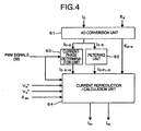
- Fig. 3 shows the structure of an electric motor driving apparatus as a first embodiment of this invention
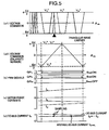
- Fig. 4 is the signal flow diagram of a process which a current reproduction unit performs.
- An inverter 2 consists mainly of an inverter main circuit 21 built with IGBTs (insulated gate bipolar transistors) and diodes, and a gate driver 22 for generating gate signals to be supplied for the IGBTs on the basis of the pulse width modulation (PWM) signals 5A delivered from a controller 5.
- the DC voltage E d supplied from a DC power source 3 is converted to three-phase AC voltages on the basis of the PWM signals 5A, and the three-phase AC voltages are supplied to an electric motor 1.
- a DC-bus current detector 4 detects the DC-bus current I 0 flowing into the inverter 2, by using a DC shunt resistor, and delivers the DC-bus current I 0 to the controller 5.
- a DC voltage detector 31 detects the DC voltage E d to be applied to the inverter 2, and delivers the DC voltage E d to the controller 5. It is to be noted here that the DC power source 3 may be replaced by the combination of an AC power source and a rectifier.
- the controller 5 comprises a current reproduction unit 6, a PWM generator 7, a dq inverter 8, a voltage command calculation unit 9, a speed command generation unit 10 and a control unit 11 having no position sensor.
- This control unit 11 is referred to hereafter as the "position-sensor-less control unit”.
- the current reproduction unit 6 reproduces the motor currents (Id, Iq) on the rotating (d-q) frame as the reproduced currents (Idc, Iqc), by using the DC-bus current I 0 detected by the DC-bus current detector 4, the DC voltage E d detected by the DC voltage detector 31, the PWM signals 5B delivered from the PWM generator 7, the voltage command values (Vd*, Vq*) delivered from the voltage command calculation unit 9, and the inverter estimated rotating phase ⁇ dc delivered from the position-sensor-less control unit 11.
- the PWM generator 7 generates the PWM signals 5A on the basis of AC voltage command values (Vu*, Vv*, Vw*) delivered from the dq inverter 8.
- the dq inverter 8 converts the voltage command values (Vd*, Vq*) into the AC voltage command values (Vu*, Vv*, Vw*).
- the voltage command calculation unit 9 calculates the voltage command values (Vd*, Vq*) for the voltages applied to the motor 1 by using the reproduced currents (Idc, Iqc) and a speed command value ⁇ 1*.
- the speed command generation unit 10 delivers the speed command value ⁇ 1* to the voltage command calculation unit 9.
- the position-sensor-less control unit 11 estimates the rotating phase ⁇ dc of the motor 1 by using the reproduced currents (Idc, Iqc) and the voltage command values (Vd*, Vq*).
- the current reproduction unit 6 the detailed structure of which is shown in Fig. 4 , comprises an AD conversion unit 61, a filtering units 62, a current-phase determination unit 63 and a current reproduction-calculation unit 64.
- the AD conversion unit 61 converts the DC-bus current I 0 and the DC voltage E d both in analog quantities into I 0-S and E 0-S both in digital quantities, respectively.
- the filtering unit 62 filters the digital DC-bus current I 0-S to deliver average DC-bus current I 0-FL-S .
- the term "average” used here refers to "filtered".
- the filtering process used here includes, for example, the filtering with first order lag and the arithmetic-average filtering.
- the current-phase determination unit 63 determines which phase current of the motor 1 the digital DC-bus current I 0-S is, on the basis of the PWM signals 5B.
- the current reproduction-calculation unit 64 reproduces the motor currents (Id, Iq) on the rotating (d-q) frame as the reproduced currents (Idc, Iqc), by using the phase-determined DC-bus current I 0-S-W (regarded as W-phase and therefore labeled with subscript -w), the averaged DC-bus current I 0-FL-S , the digital DC voltage E d-S , the PWM signals 5B, the voltage command values (Vd*, Vq*) and the inverter estimated rotating phase ⁇ dc.
- the dq inverter 8 calculates the AC voltage commands values (Vu*, Vv*, Vw*) on the basis of the voltage command values (Vd*, Vq*) delivered from the voltage command calculation unit 9.
- the calculation executed by the dq inverter 8 is based on the following expression (1).
- the PWM generator 7 converts the AC voltage command values Vu*, Vv* and Vw* to a set of the PWM signals 5A, each of which is for each of the phases u, v or w.
- the gate driver 22 in the inverter 2 drives the switching elements in response to the PWM signals 5A, so that the AC voltages corresponding to the voltage command values Vq*, Vd* are applied to the motor 1.
- the relationship among the AC voltage command values Vu*, Vv*, Vw*, the PWM carrier waveform and the PWM signals 5A, will be described later in reference to Fig. 5 .
- the electric motor driving apparatus is described as employing a conventional position/current-sensor-free vector control procedure 51.
- this embodiment can be implemented in any control procedure which is based on the reproduction of the motor phase currents on the basis of the DC-bus current.
- Fig. 5 shows the relationship between the PWM signals and the DC-bus current.
- diagram (a1) are shown the AC voltage command values Vu* (trapezium in solid line), Vv* (trapezium in dotted line) and Vw* (trapezium in long-and-short-dash line) during one period, and the triangular carrier signal (only three peaks being shown to the left).
- Diagram (a2) is the magnification of that area in diagram (a1) which is marked with a black triangle, showing the AC voltage command values and the triangular carrier signal. As shown in diagram (a2), the AC voltage command values Vu*, Vv* take a value of +Ed/2 while the AC voltage command value Vw* takes a value of -Ed/2.
- Diagram (b) shows PWM signals produced according to the relationship shown in diagram (a2).
- Diagram (c) shows the motor phase currents flowing in response to the PWM signals.
- Diagram (d) shows the DC-bus current I 0-S (solid line) and the average DC-bus current I 0-FL-S (dotted line).
- the waveforms of the DC-bus current I 0-S and the average DC-bus current I 0-FL-S are provided with the sampling points taken according to the current detection method of this embodiment.
- the current detection method of this embodiment is to simultaneously utilize the average DC-bus current I 0-FL and the instantaneous phase current I 0-S for a single phase.
- Fig. 5 shows the case where the maximum values of the sinusoidal amplitudes of thet AC voltage command values Vu*, Vv*, Vw* become greater than the value of half the DC voltage (Ed/2), that is, where excessive modulation occurs in the over-modulated PWM procedure.
- the AC voltage command values are truncated by the value equal to half the DC voltage (Ed/2), that is, limited between ⁇ Ed/2. Further, there occur intervals along the axix of the inverter estimated rotating phase ⁇ dc in which the upper and lower limiting values of the AC voltage commands overlap one another.
- the DC-bus current I 0-S takes a continuous waveform of instantaneous current (here having a descending gradient for illustrative purpose) as seen in diagram (d). Consequently, only the instantaneous current for phase W, which is the smallest phase-current and lies under the triangular carrier waveform, becomes available as seen in diagram (a2). In other words, the instantaneous currents for phases U and V, which lie over the triangular carrier waveform, cannot be observed.
- diagram (d) may be considered to represent just the averaged characteristic.
- an AD conversion unit 61 samples and holds the DC-bus current I 0 detected by the DC-bus current detector 4, and delivers the sampled DC-bus current I 0-S .
- the AD conversion unit 61 samples and holds the DC voltage E d detected by the DC voltage detector 31, and delivers the sampled DC voltage E d-s .
- a filtering unit 62 filters the sampled DC-bus current I 0-S sampled and held by the AD conversion unit 61, and delivers the sampled average DC-bus current I 0-FL-S .
- a current-phase determination unit 63 determines which of U, V and W phases the sampled DC-bus current I0-S belongs to, on the basis of the PWM signals 5B generated by the PWM generator 7.
- Fig. 4 shows the case where I 0-S is sampled from the waveform of I 0 shown in diagram (d) of Fig. 5 and the W-phase current is identified by the current-phase determination unit 63.
- the sampled DC-bus current I 0-S is referred to as the sampled W-phase DC-bus current I 0-S-W .
- a current reproduction-calculation unit 64 calculates the motor currents Idc and Iqc by using the sampled W-phase DC-bus current I 0-S-W , the sampled average DC-bus current I 0-FL-S , the sampled DC voltage E d-s , and the following expressions (2), (3) and (4).
- the expression (2) is derived from Kirchhoff's rule: the sum of the U-, V- and W-phase currents Iu, Iv and Iw vanishes.
- the expression (3) is the conversion formula that, using the inverter estimated rotating phase ⁇ dc of the motor rotating phase, transforms the U-, V- and W-phase currents Iu, Iv and Iw of the motor into the coordinate points in the rotating (d-q) frame so as to produce the motor currents Idc, Iqc in the d-q coordinate system.
- the expression (4) relates to the electric power with the power loss in the inverter circuit neglected, and indicates that the electric power derived from the voltage command values Vd*, Vq* and the motor currents Idc, Iqc in the d-q coordinate system is equal to the electric power derived from the DC voltage E d and the average DC-bus current I 0-FL .
- the current reproduction-calculation unit 64 calculates and delivers the motor currents Idc, Iqc as a result of calculations executed according to the following expression (5) using the four quantities obtained by the expressions (2), (3) and (4).
- I dc I qc 2 3 ⁇ E d - S ⁇ sin ⁇ dc - 1 3 ⁇ ⁇ ⁇ I 0 - FL - S - 2 ⁇ V q * ⁇ sin 2 1 3 ⁇ ⁇ ⁇ I 0 - S - W V q * ⁇ cos ⁇ dc - 1 3 ⁇ ⁇ + V d * ⁇ sin ⁇ dc - 1 3 ⁇ ⁇ E d - S ⁇ cos ⁇ dc - 1 3 ⁇ ⁇ ⁇ I 0 - FL - S - 2 ⁇ V d * ⁇ sin 2 1 3 ⁇ ⁇ ⁇ I 0 - S - W V q * ⁇ cos ⁇ dc - 1 3
- the current-phase determination unit 63 and the current reproduction-calculation unit 64 determines the sampled DC-bus current I0-S as the current of V- phase
- the reproduced currents Idc, Iqc are calculated by using the following expression (6) on the basis of the sampled V-phase DC-bus current I 0-S-S , the sampled average DC-bus current I 0-FL-S and the sampled DC voltage E d-s .
- I dc I qc 2 3 ⁇ E d - S ⁇ sin ⁇ dc - 2 3 ⁇ ⁇ ⁇ I 0 - FL - S - 2 ⁇ V q * ⁇ sin 2 1 3 ⁇ ⁇ ⁇ I 0 - S - V V q * ⁇ cos ⁇ dc - 2 3 ⁇ ⁇ + V d * ⁇ sin ⁇ dc - 2 3 ⁇ ⁇ E d - S ⁇ cos ⁇ dc - 2 3 ⁇ ⁇ ⁇ I 0 - FL - S - 2 ⁇ V d * ⁇ sin 2 1 3 ⁇ ⁇ ⁇ I 0 - S - V V q * ⁇ cos ⁇ dc - 2 3 ⁇ ⁇ + V d * ⁇ sin ⁇ dc - 2 3 ⁇ ⁇ ⁇
- the reproduced currents Idc, Iqc are calculated by using the following expression (7) on the basis of the sampled U-phase DC-bus current I 0-S-U , the sampled average DC-bus current I 0-FL-S and the sampled DC voltage E d-S .
- I dc I qc 2 3 ⁇ E d - S ⁇ sin ⁇ dc - ⁇ ⁇ I 0 - FL - S - 2 ⁇ V q * ⁇ sin 2 2 3 ⁇ ⁇ ⁇ I 0 - S - U V q * ⁇ cos ⁇ dc - ⁇ + V d * ⁇ sin ⁇ dc - ⁇ E d - S ⁇ cos ⁇ dc - ⁇ ⁇ I 0 - FL - S + 2 ⁇ V d * ⁇ sin 2 2 3 ⁇ ⁇ ⁇ I 0 - S - U V q * ⁇ cos ⁇ dc - ⁇ + V d * ⁇ sin ⁇ dc - ⁇
- the current reproduction unit 6 is described as filtering the DC-bus current I 0 through digital processing, but the filtering process may be performed in analog fashion, for example, by replacing the filtering unit 62 by an analog filtering circuit 62A consisting of resistors and capacitors, as shown in Fig. 6 .
- the average DC-bus current I 0-FL and the instantaneous phase-current I 0-S for a single phase are utilized simultaneously so that the reproduction of current becomes possible even under the field-weakening control using the over-modulated PWM procedure.
- two sampling points are designated in diagram (d) of Fig. 5 .
- the over-modulated PWM control enables the voltage applied to the motor to be substantially increased. Namely, as described above with Fig. 1 , the voltage can be increased from V 0 to 1.27 ⁇ V 0 .
- Fig. 7 schematically shows a current reproduction unit 6C equipped with a current detection changeover unit 67, which is a variation of the current reproduction unit 6 shown in Fig. 4 .
- Figs. 7 also shows the flow of signal processing in the current reproduction unit 6C.
- the current reproduction unit 6C is so designed as to change over between a first current reproduction section (using such a current detecting method described as with Fig. 4 ) that simultaneously utilizes the average DC-bus current I 0-FL and the instantaneous phase current I 0-S for a single phase and a second current reproduction section (using a well-known current detection method) that reproduces three-phase currents from the instantaneous phase- currents for two phases.
- Fig. 8 shows the relationship between the PWM signals and the DC-bus current, observed for low speed motor rotations, i.e. rpm's equal to or lower than N1, along with the way both the DC-bus current I 0 and the average DC-bus current I 0-FL are sampled.
- Figs. 9(A) and 9(B) are enlarged versions of Fig. 8(d) , prepared for detailed explanation of sampling.
- FIG. 9 A-part of Fig. 9 shows the way the second current reproduction section performs sampling, the DC-bus current I 0 being sampled as sampling 1 and sampling 2.
- FIG. 9 shows the way the first current reproduction section performs sampling, the DC-bus current I 0 being sampled as sampling 2 and the average DC-bus current I 0-FL as sampling 3.
- a filtering unit 62, a current-phase determination unit 63 and a current reproduction-calculation unit 64 constituting the first current reproduction section in the current reproduction unit 6C, operate in the same manner as the corresponding counterparts shown in Fig. 4 and described above.
- the second current reproduction section in the current reproduction unit 6C consists of a current-phase determination unit 65 and a current reproduction-calculation unit 66, and delivers reproduced currents Idc2 and Iqc2.
- the current reproduction unit 6C the reader is requested to refer to JP-A-02-197295 . In what follows, description is briefly made of the case to which the waveforms shown in Fig. 8 are related.
- the current-phase determination unit 65 determines the sampled DC-bus currents I 0-S sampled in the AD conversion unit 61 as the instantaneous phase-currents of W- and U-phases on the basis of the PWM signals 5B, and delivers the instantaneous phase-currents for two phases, i.e. the sampled W-phase DC-bus current I 0-S-W and the sampled U-phase DC-bus current I 0-S-U .
- the current reproduction-calculation unit 66 derives the V-phase current Iv through the use of the expression (2) regarding the sum of the currents for three phases, on the basis of the thus obtained instantaneous phase-currents for two phases. Then, the current reproduction-calculation unit 66 delivers the reproduced currents Idc2 and Iqc2 through the use of the expression (3) for transforming the U-, V- and W-phase currents into the currents along the d-q axis in the rotating (d-q) frame, on the basis of the sampled W-phase DC-bus current I 0-S-W , the sampled U-phase DC-bus current I 0-S-U , the thus obtained V-phase current Iv and the inverter estimated rotating phase ⁇ dc.
- the current detection changeover unit 67 compares the averaged DC-bus current I 0-FL with a preset value, and if the former is equal to or greater than the latter, the current detection changeover unit 67 delivers the reproduced currents Idc2 and Iqc2 calculated by the first current reproduction section as the reproduced currents Idc and Iqc, respectively. In other words, if the averaged DC-bus current I 0-FL is equal to or greater than the preset value, the current detection changeover unit 67 selects the first current reproduction-calculation section, while if the averaged DC-bus current I 0-FL is smaller than the preset value, the current detection changeover unit 67 selects the second current reproduction-calculation section.
- the current detection changeover unit 67 changes over the current detection methods on the basis of the comparison of the averaged DC-bus current I 0-FL with a preset value.
- the current detection changeover unit 67 may be so designed as to change over the current detection methods by comparing the rpm of the motor 1 with a preset value. In this embodiment, such a preset value is regarded as N1.
- the motor phase-currents can be reproduced with high precision from low rpm range up to high rpm range.
- the DC power is calculated from the average DC-bus current I 0-FL-S and the DC voltage E d-s . Accordingly, when the average DC-bus current I 0-FL-S becomes small in the low rpm range, current sampling (i.e. sampling 3 shown in B-pat of Fig. 9 is vulnerable to noise so that precision in current reproduction is degraded.
- the instantaneous currents for two phases can be sampled (as samplings 1 and 2) from the DC-bus current I 0 that is greater than the average DC-bus current I 0-FL as shown in A-part of Fig. 9 . Consequently, current production becomes possible without degrading precision even in the low rpm range.
- the second current reproduction section is selected in the low rpm range, current can be detected without degrading precision in detection.
- phase currents of the motor 1 can be reproduced with high precision from the low rpm range to the high rpm range if the current detection methods are selectively changed over between the low and high rpm ranges. Therefore, it is useful to replace the current reproduction unit 6 by the current reproduction unit 6C shown in Figs. 7 , that can change over between the first current reproduction section and the second current reproduction section.
- Fig. 10 schematically shows the entire system of an air conditioner.
- An air conditioner 100 consists mainly of an outdoor unit 101, an indoor unit 102 and tubing 103 connecting the outdoor unit 101 and the indoor unit 102. Heat is exchanged between the outdoor unit 101 and the indoor unit 102 by means of refrigerant circulated through the tubing 103.
- the outdoor unit 101 for exchanging heat with outdoor space comprises a compressor 104 for compressing refrigerant, a compressor driving motor 105 for driving the compressor 104, a motor driving apparatus 106 for controlling the compressor driving motor 105 and a heat exchanger 107 for exchanging heat between the outdoor and indoor units 101 and 102.
- the indoor unit 102 for exchanging heat with indoor space comprises a heat exchanger 108 for exchanging heat with indoor space, and a blower 109 for dispersing heat generated by the heat exchanger 108 into indoor space.
- APF Annual performance factor
- the voltage saturation range shown in Fig. 1 is expanded where the motor counter emf exceeds the voltage that the inverter can supply. Consequently, reactive current generated through the field-weakening control is conducted through the motor to a greater extent in the high rpm range. As a result, as shown with solid curve in Fig 11 , the compressor driving motor incurs a large degradation of efficiency in the high rpm range.
- the reproduction of motor current becomes possible even in the case where the voltage command values overlap in the over-modulated PWM control.
- the voltage that the inverter can supply can be increased to the extent that the waveforms of the AC voltage command values approach rectangular waveforms (to the extent that rpm approaches N2 and the voltage approaches 1.27 ⁇ V 0 in Fig. 1 ) so that the reactive current conducted through the motor can be decreased.
- the increase in the voltage that the inverter can supply can decrease the reactive current flowing in the field-weakening control even when the DC voltage Ed is constant, as shown in Fig. 1 . Consequently, the loss due to current can be decreased, and also the degradation of efficiency can be suppressed in the high rpm range exceeding the rpm of N3 at which the efficiency takes a peek, as shown with long-and-short dash curve in Fig. 11 . Further, as shown in Fig. 2 , the torque that the compressor driving motor can generate is increased, that is, the motor can generate higher mechanical outputs, in the high rpm range.
- the current detection method of this embodiment and the over-modulated PWM control are used in combination for the compressor driving system of an air conditioner, high efficiency can be enjoyed even when the compressor driving motor is operated at high rpm's. This means that the circulation rate of refrigerant can be increased, that is, the output of the air-conditioner can be increased.
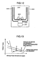
- Fig. 12 depicts in vertical cross-section the entire structure of a washer.
- a washer 200 comprises a tub 205, a basket 204, an agitator 203 for agitating water and wash in the basket 204, an agitator driving motor 202 for rotating the agitator 203, and a motor driving apparatus 201 for controlling the agitator driving motor 202.
- Fig. 13 graphically shows the relationship between the rpm and the torque, of the agitator driving motor 202.
- the agitator driving motor 202 operates at the operating point A corresponding to the operation at low rpm with high torque, and, at the time of dehydration, it operates under the field weakening control at the operating point B corresponding to the operation at high rpm with low torque.
- the operating point of the agitator driving motor 202 In order to cope with the growing demands for increasing the washer capacity and shortening the time for dehydration, the operating point of the agitator driving motor 202 must be shifted from the point B to the point C or D.
- the agitator driving motor 202 normally operates at the operating point A which corresponds to the low rpm operation with height torque and high efficiency. Therefore, a permanent magnet motor is used as the agitator driving motor for the purpose of intensifying the internal magnetic flux. As described above, with the permanent magnet motor, the torque that the motor can generate is lowered due to the expansion of the voltage saturation range at high rpm operations so that the motor cannot be operated at the operating points C and D.
- the reproduction of motor current becomes possible even in the case where the voltage command values overlap in the over-modulated PWM control.
- the voltage that the inverter can supply can be increased to the extent that the waveforms of the AC voltage command values approach rectangular waveforms.
- the increase in the voltage that the inverter can supply results in the increase in the torque that the motor can generate at operation under the field-weakening control. Accordingly, the operating characteristic of the agitator driving motor 202 can be shifted from the solid line to the dotted lime in Fig. 13 . Hence, the agitator driving motor 202 can be operated at the operating points C and D.
- the agitator driving motor 202 can now operate at the operating point C where it can rotate at the same rpm as at the operating point B but with greater torque, the capacity of the washer can be increased if using such an agitator driving motor. Further, since the agitator driving motor 202 can also operate at the operating point D where it can rotate with the same torque as at the operating point B but at higher rpm, the time for dehydration can be shortened.
- the current detection method according to this embodiment is applied to a washer, the current sensor that must otherwise be used for the agitator driving motor can be dispensed with, so that the size and cost of the washer can be reduced. Further, since the current detection method of this embodiment and the over-modulated PWM control are used in combination, the agitator driving motor can rotate at high rpm's, so that the time for dehydration can be shortened. Moreover, since the agitator driving motor can rotate with high torque, the capacity of the washer can be increased.
Landscapes
- Engineering & Computer Science (AREA)
- Power Engineering (AREA)
- Control Of Ac Motors In General (AREA)
- Control Of Motors That Do Not Use Commutators (AREA)
- Inverter Devices (AREA)
- Control Of Washing Machine And Dryer (AREA)
- Air Conditioning Control Device (AREA)
Claims (10)
- Umrichtersteuerungsvorrichtung (5) mit einer Stromrekonstruktionseinheit (6),
welche Informationen von einem Gleichstrombus-Stromdetektor (4) ausgibt, zur Erfassung der momentanen Phasenströme, die in einen elektrischen Motor (1) fließen und die in dem Gleichstrombus-Strom enthalten sind, der von einer Gleichstromquelle (3) in den Umrichter (2) fließt, und
welche Phasenströme, die in den Motor (1) fließen, auf der Grundlage von Werten der momentanen Phasenströme rekonstruiert, wobei die Spannungssteuersignale der an den Umrichter (2) anzulegenden Spannungen unter Verwendung der Phasenströme berechnet werden,
dadurch gekennzeichnet, dass bei einem vorbestimmten Wert des gemittelten Gleichstrombus-Stroms im Spannungssättigungsbereich die Stromrekonstruktionseinheit (6) die Phasenströme, die in den Motor (1) fließen, auf der Grundlage des gemittelten Gleichstrombus-Stroms (I0-FL-S) berechnet, der durch Filtern des Gleichstrombus-Stroms, eines momentanen Phasenstroms für eine einzelne Phase (I0-S-U, I0-S-V, I0-S-W), der erfassten Gleichspannung (Ed-S) und des Drehwinkels (θdc) des Drehrahmens (d-q) erhalten wird. - Umrichtersteuerungsvorrichtung (5) nach Anspruch 1, wobei der Spannungssättigungsbereich der Bereich ist, bei dem die Drehzahl größer oder gleich einem vorbestimmten Wert ist.
- Umrichtersteuerungsvorrichtung (5) nach Anspruch 1 oder 2, wobei die Stromrekonstruktionseinheit (6C) einen ersten Stromrekonstruktionsabschnitt aufweist zum Berechnen der Phasenströme, die in den Motor (1) fließen, auf der Grundlage des gemittelten Gleichstrombus-Stroms, der erhalten wird durch Filtern des Gleichstrombus-Stroms und eines momentanen Phasenstroms für eine einzelne Phase, und einen zweiten Stromrekonstruktionsabschnitt zum Berechnen der Phasenströme, die in den Motor (1) fließen unter Verwendung momentaner Phasenströme für zwei Phasen, wobei im Sättigungsspannungsbereich die Stromrekonstruktionseinheit (6C) die Spannungssteuersignale für die an den Umrichter (2) anzulegenden Spannungen berechnet unter Verwendung der durch den ersten Stromrekonstruktionsabschnitt berechneten Phasenströme.
- Umrichtersteuerungsvorrichtung (5) nach Anspruch 3, wobei der Spannungssättigungsbereich der Bereich ist, in dem die Drehzahl größer oder gleich einem vorbestimmten Wert ist.
- Umrichtersteuerungsvorrichtung (5) nach Anspruch 4, wobei, wenn der Motor (1) mit einer Drehzahl betrieben wird, die kleiner als ein vorgegebener Wert ist, die Stromrekonstruktionseinheit (6C) die Spannungssteuersignale für die an den Umrichter (2) anzulegenden Spannungen berechnet unter Verwendung der Phasenströme, die von dem zweiten Stromrekonstruktionsabschnitt berechnet wurden.
- Umrichtersteuerungsvorrichtung (5) nach Anspruch 3, wobei die Stromrekonstruktionseinheit (6C) ferner eine Stromerfassungsumschalteinheit (67) aufweist zum Umschalten zwischen dem ersten Stromrekonstruktionsabschnitt für die Berechnung der Phasenströme, die in den Motor im Sättigungsspannungsbereich fließen, und dem zweiten Stromrekonstruktionsabschnitt zum Berechnen der Phasenströme, die in den Motor in dem Drehzahlbereich fließen, der von dem Sättigungsspannungsbereich verschieden ist.
- Klimaanlage, bei der die Umrichtersteuerungsvorrichtung (5) nach einem der Ansprüche 1 bis 6 bei der Motorsteuerungsvorrichtung (106) zum Steuern des Kompressorantriebsmotors (105) verwendet wird.
- Klimaanlage nach Anspruch 7, bei der die Umrichtersteuerungsvorrichtung (5) im hohen Drehzahlbereich im übermodulierten PWM-Modus betrieben wird, um die Phasenströme zu reduzieren, die in die Motorsteuerungsvorrichtung (106) fließen.
- Waschmaschine, bei der die Umrichtersteuerungsvorrichtung (5) nach einem der Ansprüche 1 bis 6 bei der Motorsteuerungsvorrichtung (201) zum Steuern des Motors (202), der das Rührwerk (203) oder die Trommel (204) antreibt, verwendet wird.
- Waschmaschine nach Anspruch 9, bei der die Umrichtersteuerungsvorrichtung (5) im hohen Drehzahlbereich im übermodulierten PWM-Steuermodus betrieben wird, um das Drehmoment des Motors (202) zu steigern.
Applications Claiming Priority (1)
| Application Number | Priority Date | Filing Date | Title |
|---|---|---|---|
| JP2009139769A JP5417051B2 (ja) | 2009-06-11 | 2009-06-11 | インバータの制御装置、及び、それを用いた空調機,洗濯機 |
Publications (3)
| Publication Number | Publication Date |
|---|---|
| EP2262092A1 EP2262092A1 (de) | 2010-12-15 |
| EP2262092A8 EP2262092A8 (de) | 2011-02-16 |
| EP2262092B1 true EP2262092B1 (de) | 2012-03-07 |
Family
ID=42710485
Family Applications (1)
| Application Number | Title | Priority Date | Filing Date |
|---|---|---|---|
| EP10006087A Not-in-force EP2262092B1 (de) | 2009-06-11 | 2010-06-11 | Umrichtersteuerungsvorrichtung und Klimaanlage und diese Vorrichtung benutzende Waschmaschine |
Country Status (6)
| Country | Link |
|---|---|
| EP (1) | EP2262092B1 (de) |
| JP (1) | JP5417051B2 (de) |
| KR (1) | KR101114723B1 (de) |
| CN (1) | CN101924486B (de) |
| AT (1) | ATE548794T1 (de) |
| ES (1) | ES2383783T3 (de) |
Families Citing this family (12)
| Publication number | Priority date | Publication date | Assignee | Title |
|---|---|---|---|---|
| JP5373863B2 (ja) * | 2011-08-04 | 2013-12-18 | シャープ株式会社 | 同期モータ駆動装置およびそれを備えた冷凍サイクルを有する機器 |
| JP5444304B2 (ja) * | 2011-10-25 | 2014-03-19 | ファナック株式会社 | 無効電流指令作成部を有するモータ駆動装置 |
| JP6000801B2 (ja) * | 2012-10-24 | 2016-10-05 | ジョンソンコントロールズ ヒタチ エア コンディショニング テクノロジー(ホンコン)リミテッド | モータ制御装置、およびそれを用いた空気調和機 |
| JP6046446B2 (ja) * | 2012-10-26 | 2016-12-14 | 日立アプライアンス株式会社 | ベクトル制御装置、およびそれを用いたモータ制御装置、空調機 |
| JP6317904B2 (ja) * | 2013-10-02 | 2018-04-25 | 日立ジョンソンコントロールズ空調株式会社 | モータ制御装置、及び空気調和機 |
| JP6267762B2 (ja) * | 2016-09-26 | 2018-01-24 | 株式会社ナカニシ | Dcブラシレスモータの駆動装置 |
| EP4094355A1 (de) * | 2020-01-23 | 2022-11-30 | MAHLE International GmbH | Stromversorgungssteuerschaltungen mit shunt-widerständen für synchronmotoren |
| CN113872484B (zh) * | 2021-09-27 | 2024-01-19 | 佛山市顺德区美的电子科技有限公司 | 三相电流重构方法、装置、设备和存储介质 |
| CN116287762A (zh) * | 2023-02-09 | 2023-06-23 | 昆明理工大学 | 湿法炼锌过程含锌物料搅拌溶解强化方法及设备 |
| JP7708135B2 (ja) * | 2023-02-21 | 2025-07-15 | トヨタ自動車株式会社 | 推定システム |
| JPWO2025069183A1 (de) * | 2023-09-26 | 2025-04-03 | ||
| JPWO2025069182A1 (de) * | 2023-09-26 | 2025-04-03 |
Family Cites Families (17)
| Publication number | Priority date | Publication date | Assignee | Title |
|---|---|---|---|---|
| JPS62221897A (ja) * | 1986-03-24 | 1987-09-29 | Mitsubishi Electric Corp | 電動機の制御装置 |
| JP2712470B2 (ja) * | 1989-01-23 | 1998-02-10 | 松下電器産業株式会社 | インバータ装置の電流検出装置 |
| JP3084994B2 (ja) * | 1993-01-26 | 2000-09-04 | 松下電器産業株式会社 | 自動車空調用電動コンプレッサーの制御駆動装置 |
| WO2002091558A1 (en) | 2001-04-24 | 2002-11-14 | Mitsubishi Denki Kabushiki Kaisha | System for controlling synchronous motor |
| JP3651595B2 (ja) * | 2001-12-13 | 2005-05-25 | 株式会社東芝 | 洗濯機のインバータ装置及び洗濯乾燥機のインバータ装置 |
| JP3843391B2 (ja) * | 2002-01-17 | 2006-11-08 | 株式会社日立製作所 | 同期電動機駆動装置 |
| GB0213098D0 (en) * | 2002-06-07 | 2002-07-17 | Trw Ltd | Motor control device |
| JP3971979B2 (ja) * | 2002-09-13 | 2007-09-05 | 日立アプライアンス株式会社 | 空気調和装置 |
| JP4517793B2 (ja) | 2004-09-14 | 2010-08-04 | 株式会社日立製作所 | 永久磁石同期モータの制御装置及びモジュール |
| JP2006136102A (ja) * | 2004-11-04 | 2006-05-25 | Denso Corp | モータの駆動制御装置 |
| US7119530B2 (en) | 2005-02-04 | 2006-10-10 | Delphi Technologies, Inc. | Motor phase current measurement using a single DC bus shunt sensor |
| DE102005025402A1 (de) | 2005-06-02 | 2006-12-07 | Rohde & Schwarz Gmbh & Co. Kg | Verfahren zur Klassifizierung von digital modulierten Signalen |
| JP4847060B2 (ja) * | 2005-07-15 | 2011-12-28 | 日立オートモティブシステムズ株式会社 | 交流モータ駆動装置及びその制御方法 |
| JP2007159368A (ja) * | 2005-12-08 | 2007-06-21 | Toyota Motor Corp | モータ駆動システムの制御装置 |
| JP2006271198A (ja) * | 2006-06-02 | 2006-10-05 | Hitachi Ltd | 同期電動機駆動装置 |
| JP5056106B2 (ja) * | 2007-03-27 | 2012-10-24 | パナソニック株式会社 | モータ駆動用インバータ制御装置および該装置を用いた機器 |
| JP2009124869A (ja) * | 2007-11-15 | 2009-06-04 | Meidensha Corp | 同期電動機のV/f制御装置 |
-
2009
- 2009-06-11 JP JP2009139769A patent/JP5417051B2/ja active Active
-
2010
- 2010-06-07 CN CN201010198894.1A patent/CN101924486B/zh active Active
- 2010-06-10 KR KR1020100054742A patent/KR101114723B1/ko not_active Expired - Fee Related
- 2010-06-11 AT AT10006087T patent/ATE548794T1/de active
- 2010-06-11 EP EP10006087A patent/EP2262092B1/de not_active Not-in-force
- 2010-06-11 ES ES10006087T patent/ES2383783T3/es active Active
Also Published As
| Publication number | Publication date |
|---|---|
| KR20100133309A (ko) | 2010-12-21 |
| CN101924486A (zh) | 2010-12-22 |
| ATE548794T1 (de) | 2012-03-15 |
| ES2383783T3 (es) | 2012-06-26 |
| EP2262092A8 (de) | 2011-02-16 |
| JP5417051B2 (ja) | 2014-02-12 |
| EP2262092A1 (de) | 2010-12-15 |
| CN101924486B (zh) | 2014-03-19 |
| JP2010288359A (ja) | 2010-12-24 |
| KR101114723B1 (ko) | 2012-04-17 |
Similar Documents
| Publication | Publication Date | Title |
|---|---|---|
| EP2262092A1 (de) | Wechselrichtersteuerungsvorrichtung und Klimaanlage und diese Vorrichtung benutzende Waschmaschine | |
| EP2161828B1 (de) | Antriebssystem und steuerverfahren dafür | |
| US6844697B2 (en) | Motor controller | |
| US8373380B2 (en) | Device and method for controlling alternating-current motor | |
| US8232753B2 (en) | Control device for electric motor drive apparatus | |
| CN102577093B (zh) | 电动机驱动装置的控制装置 | |
| EP2343800B1 (de) | Steuerungsvorrichtung und steuerungsverfahren für einen elektrischen wechselstrommotor | |
| EP2322374A1 (de) | Stromwandler | |
| US8148926B2 (en) | Permanent magnet synchronization motor vector control device | |
| WO2006121093A1 (ja) | モータ駆動システムの制御装置およびそれを備える電動車両 | |
| JP6078282B2 (ja) | 交流電動機駆動システム及び電動機車両 | |
| JP6046446B2 (ja) | ベクトル制御装置、およびそれを用いたモータ制御装置、空調機 | |
| CN104767455A (zh) | 一种混合励磁同步电机无位置传感器直接转矩控制方法 | |
| JP5734138B2 (ja) | モータ制御装置及びモータ駆動システム、並びにモータ制御方法 | |
| JP6293401B2 (ja) | 空気調和機のモータ制御装置及び空気調和機 | |
| JP2005237172A (ja) | 同期機の制御装置 | |
| JP2009273302A (ja) | 電動モータの制御装置 | |
| JP2002165499A (ja) | モータ制御装置 | |
| JP7417941B2 (ja) | 回転電機制御装置 | |
| JP2009131024A (ja) | 電力変換装置及びその制御方法 | |
| KR20200082257A (ko) | 싱글 분권 센서리스 pmsm의 임계구간 제어방법 | |
| JP2005117818A5 (de) | ||
| JP2005117818A (ja) | 永久磁石形同期電動機制御装置 | |
| JP2026064079A (ja) | モータ制御装置 | |
| JP2026003351A (ja) | 電動コンプレッサのモータ制御装置 |
Legal Events
| Date | Code | Title | Description |
|---|---|---|---|
| PUAI | Public reference made under article 153(3) epc to a published international application that has entered the european phase |
Free format text: ORIGINAL CODE: 0009012 |
|
| 17P | Request for examination filed |
Effective date: 20101012 |
|
| AK | Designated contracting states |
Kind code of ref document: A1 Designated state(s): AL AT BE BG CH CY CZ DE DK EE ES FI FR GB GR HR HU IE IS IT LI LT LU LV MC MK MT NL NO PL PT RO SE SI SK SM TR |
|
| AX | Request for extension of the european patent |
Extension state: BA ME RS |
|
| GRAP | Despatch of communication of intention to grant a patent |
Free format text: ORIGINAL CODE: EPIDOSNIGR1 |
|
| GRAS | Grant fee paid |
Free format text: ORIGINAL CODE: EPIDOSNIGR3 |
|
| GRAA | (expected) grant |
Free format text: ORIGINAL CODE: 0009210 |
|
| AK | Designated contracting states |
Kind code of ref document: B1 Designated state(s): AL AT BE BG CH CY CZ DE DK EE ES FI FR GB GR HR HU IE IS IT LI LT LU LV MC MK MT NL NO PL PT RO SE SI SK SM TR |
|
| REG | Reference to a national code |
Ref country code: GB Ref legal event code: FG4D |
|
| REG | Reference to a national code |
Ref country code: AT Ref legal event code: REF Ref document number: 548794 Country of ref document: AT Kind code of ref document: T Effective date: 20120315 Ref country code: CH Ref legal event code: EP |
|
| REG | Reference to a national code |
Ref country code: IE Ref legal event code: FG4D |
|
| REG | Reference to a national code |
Ref country code: DE Ref legal event code: R096 Ref document number: 602010000944 Country of ref document: DE Effective date: 20120503 |
|
| REG | Reference to a national code |
Ref country code: ES Ref legal event code: FG2A Ref document number: 2383783 Country of ref document: ES Kind code of ref document: T3 Effective date: 20120626 |
|
| REG | Reference to a national code |
Ref country code: NL Ref legal event code: VDEP Effective date: 20120307 |
|
| PG25 | Lapsed in a contracting state [announced via postgrant information from national office to epo] |
Ref country code: NL Free format text: LAPSE BECAUSE OF FAILURE TO SUBMIT A TRANSLATION OF THE DESCRIPTION OR TO PAY THE FEE WITHIN THE PRESCRIBED TIME-LIMIT Effective date: 20120307 Ref country code: LT Free format text: LAPSE BECAUSE OF FAILURE TO SUBMIT A TRANSLATION OF THE DESCRIPTION OR TO PAY THE FEE WITHIN THE PRESCRIBED TIME-LIMIT Effective date: 20120307 Ref country code: HR Free format text: LAPSE BECAUSE OF FAILURE TO SUBMIT A TRANSLATION OF THE DESCRIPTION OR TO PAY THE FEE WITHIN THE PRESCRIBED TIME-LIMIT Effective date: 20120307 Ref country code: NO Free format text: LAPSE BECAUSE OF FAILURE TO SUBMIT A TRANSLATION OF THE DESCRIPTION OR TO PAY THE FEE WITHIN THE PRESCRIBED TIME-LIMIT Effective date: 20120607 |
|
| LTIE | Lt: invalidation of european patent or patent extension |
Effective date: 20120307 |
|
| PG25 | Lapsed in a contracting state [announced via postgrant information from national office to epo] |
Ref country code: GR Free format text: LAPSE BECAUSE OF FAILURE TO SUBMIT A TRANSLATION OF THE DESCRIPTION OR TO PAY THE FEE WITHIN THE PRESCRIBED TIME-LIMIT Effective date: 20120608 Ref country code: FI Free format text: LAPSE BECAUSE OF FAILURE TO SUBMIT A TRANSLATION OF THE DESCRIPTION OR TO PAY THE FEE WITHIN THE PRESCRIBED TIME-LIMIT Effective date: 20120307 Ref country code: LV Free format text: LAPSE BECAUSE OF FAILURE TO SUBMIT A TRANSLATION OF THE DESCRIPTION OR TO PAY THE FEE WITHIN THE PRESCRIBED TIME-LIMIT Effective date: 20120307 |
|
| REG | Reference to a national code |
Ref country code: AT Ref legal event code: MK05 Ref document number: 548794 Country of ref document: AT Kind code of ref document: T Effective date: 20120307 |
|
| PG25 | Lapsed in a contracting state [announced via postgrant information from national office to epo] |
Ref country code: CY Free format text: LAPSE BECAUSE OF FAILURE TO SUBMIT A TRANSLATION OF THE DESCRIPTION OR TO PAY THE FEE WITHIN THE PRESCRIBED TIME-LIMIT Effective date: 20120307 |
|
| PG25 | Lapsed in a contracting state [announced via postgrant information from national office to epo] |
Ref country code: RO Free format text: LAPSE BECAUSE OF FAILURE TO SUBMIT A TRANSLATION OF THE DESCRIPTION OR TO PAY THE FEE WITHIN THE PRESCRIBED TIME-LIMIT Effective date: 20120307 Ref country code: SE Free format text: LAPSE BECAUSE OF FAILURE TO SUBMIT A TRANSLATION OF THE DESCRIPTION OR TO PAY THE FEE WITHIN THE PRESCRIBED TIME-LIMIT Effective date: 20120307 Ref country code: SI Free format text: LAPSE BECAUSE OF FAILURE TO SUBMIT A TRANSLATION OF THE DESCRIPTION OR TO PAY THE FEE WITHIN THE PRESCRIBED TIME-LIMIT Effective date: 20120307 Ref country code: IS Free format text: LAPSE BECAUSE OF FAILURE TO SUBMIT A TRANSLATION OF THE DESCRIPTION OR TO PAY THE FEE WITHIN THE PRESCRIBED TIME-LIMIT Effective date: 20120707 Ref country code: EE Free format text: LAPSE BECAUSE OF FAILURE TO SUBMIT A TRANSLATION OF THE DESCRIPTION OR TO PAY THE FEE WITHIN THE PRESCRIBED TIME-LIMIT Effective date: 20120307 Ref country code: BE Free format text: LAPSE BECAUSE OF FAILURE TO SUBMIT A TRANSLATION OF THE DESCRIPTION OR TO PAY THE FEE WITHIN THE PRESCRIBED TIME-LIMIT Effective date: 20120307 Ref country code: CZ Free format text: LAPSE BECAUSE OF FAILURE TO SUBMIT A TRANSLATION OF THE DESCRIPTION OR TO PAY THE FEE WITHIN THE PRESCRIBED TIME-LIMIT Effective date: 20120307 Ref country code: PL Free format text: LAPSE BECAUSE OF FAILURE TO SUBMIT A TRANSLATION OF THE DESCRIPTION OR TO PAY THE FEE WITHIN THE PRESCRIBED TIME-LIMIT Effective date: 20120307 |
|
| PG25 | Lapsed in a contracting state [announced via postgrant information from national office to epo] |
Ref country code: PT Free format text: LAPSE BECAUSE OF FAILURE TO SUBMIT A TRANSLATION OF THE DESCRIPTION OR TO PAY THE FEE WITHIN THE PRESCRIBED TIME-LIMIT Effective date: 20120709 Ref country code: SK Free format text: LAPSE BECAUSE OF FAILURE TO SUBMIT A TRANSLATION OF THE DESCRIPTION OR TO PAY THE FEE WITHIN THE PRESCRIBED TIME-LIMIT Effective date: 20120307 |
|
| PLBE | No opposition filed within time limit |
Free format text: ORIGINAL CODE: 0009261 |
|
| STAA | Information on the status of an ep patent application or granted ep patent |
Free format text: STATUS: NO OPPOSITION FILED WITHIN TIME LIMIT |
|
| PG25 | Lapsed in a contracting state [announced via postgrant information from national office to epo] |
Ref country code: AT Free format text: LAPSE BECAUSE OF FAILURE TO SUBMIT A TRANSLATION OF THE DESCRIPTION OR TO PAY THE FEE WITHIN THE PRESCRIBED TIME-LIMIT Effective date: 20120307 Ref country code: DK Free format text: LAPSE BECAUSE OF FAILURE TO SUBMIT A TRANSLATION OF THE DESCRIPTION OR TO PAY THE FEE WITHIN THE PRESCRIBED TIME-LIMIT Effective date: 20120307 Ref country code: MC Free format text: LAPSE BECAUSE OF NON-PAYMENT OF DUE FEES Effective date: 20120630 |
|
| 26N | No opposition filed |
Effective date: 20121210 |
|
| PG25 | Lapsed in a contracting state [announced via postgrant information from national office to epo] |
Ref country code: MK Free format text: LAPSE BECAUSE OF FAILURE TO SUBMIT A TRANSLATION OF THE DESCRIPTION OR TO PAY THE FEE WITHIN THE PRESCRIBED TIME-LIMIT Effective date: 20120307 |
|
| REG | Reference to a national code |
Ref country code: IE Ref legal event code: MM4A |
|
| REG | Reference to a national code |
Ref country code: DE Ref legal event code: R097 Ref document number: 602010000944 Country of ref document: DE Effective date: 20121210 |
|
| PG25 | Lapsed in a contracting state [announced via postgrant information from national office to epo] |
Ref country code: IE Free format text: LAPSE BECAUSE OF NON-PAYMENT OF DUE FEES Effective date: 20120611 |
|
| PG25 | Lapsed in a contracting state [announced via postgrant information from national office to epo] |
Ref country code: BG Free format text: LAPSE BECAUSE OF FAILURE TO SUBMIT A TRANSLATION OF THE DESCRIPTION OR TO PAY THE FEE WITHIN THE PRESCRIBED TIME-LIMIT Effective date: 20120607 Ref country code: MT Free format text: LAPSE BECAUSE OF FAILURE TO SUBMIT A TRANSLATION OF THE DESCRIPTION OR TO PAY THE FEE WITHIN THE PRESCRIBED TIME-LIMIT Effective date: 20120307 |
|
| PG25 | Lapsed in a contracting state [announced via postgrant information from national office to epo] |
Ref country code: AL Free format text: LAPSE BECAUSE OF FAILURE TO SUBMIT A TRANSLATION OF THE DESCRIPTION OR TO PAY THE FEE WITHIN THE PRESCRIBED TIME-LIMIT Effective date: 20120307 |
|
| PG25 | Lapsed in a contracting state [announced via postgrant information from national office to epo] |
Ref country code: TR Free format text: LAPSE BECAUSE OF FAILURE TO SUBMIT A TRANSLATION OF THE DESCRIPTION OR TO PAY THE FEE WITHIN THE PRESCRIBED TIME-LIMIT Effective date: 20120307 |
|
| PG25 | Lapsed in a contracting state [announced via postgrant information from national office to epo] |
Ref country code: SM Free format text: LAPSE BECAUSE OF FAILURE TO SUBMIT A TRANSLATION OF THE DESCRIPTION OR TO PAY THE FEE WITHIN THE PRESCRIBED TIME-LIMIT Effective date: 20120307 Ref country code: LU Free format text: LAPSE BECAUSE OF NON-PAYMENT OF DUE FEES Effective date: 20120611 |
|
| PG25 | Lapsed in a contracting state [announced via postgrant information from national office to epo] |
Ref country code: HU Free format text: LAPSE BECAUSE OF FAILURE TO SUBMIT A TRANSLATION OF THE DESCRIPTION OR TO PAY THE FEE WITHIN THE PRESCRIBED TIME-LIMIT Effective date: 20100611 |
|
| REG | Reference to a national code |
Ref country code: CH Ref legal event code: PL |
|
| PG25 | Lapsed in a contracting state [announced via postgrant information from national office to epo] |
Ref country code: CH Free format text: LAPSE BECAUSE OF NON-PAYMENT OF DUE FEES Effective date: 20140630 Ref country code: LI Free format text: LAPSE BECAUSE OF NON-PAYMENT OF DUE FEES Effective date: 20140630 |
|
| REG | Reference to a national code |
Ref country code: FR Ref legal event code: PLFP Year of fee payment: 7 |
|
| PGFP | Annual fee paid to national office [announced via postgrant information from national office to epo] |
Ref country code: ES Payment date: 20160510 Year of fee payment: 7 Ref country code: DE Payment date: 20160607 Year of fee payment: 7 Ref country code: GB Payment date: 20160608 Year of fee payment: 7 |
|
| PGFP | Annual fee paid to national office [announced via postgrant information from national office to epo] |
Ref country code: FR Payment date: 20160516 Year of fee payment: 7 |
|
| PGFP | Annual fee paid to national office [announced via postgrant information from national office to epo] |
Ref country code: IT Payment date: 20160621 Year of fee payment: 7 |
|
| REG | Reference to a national code |
Ref country code: DE Ref legal event code: R119 Ref document number: 602010000944 Country of ref document: DE |
|
| GBPC | Gb: european patent ceased through non-payment of renewal fee |
Effective date: 20170611 |
|
| REG | Reference to a national code |
Ref country code: FR Ref legal event code: ST Effective date: 20180228 |
|
| PG25 | Lapsed in a contracting state [announced via postgrant information from national office to epo] |
Ref country code: DE Free format text: LAPSE BECAUSE OF NON-PAYMENT OF DUE FEES Effective date: 20180103 Ref country code: GB Free format text: LAPSE BECAUSE OF NON-PAYMENT OF DUE FEES Effective date: 20170611 |
|
| PG25 | Lapsed in a contracting state [announced via postgrant information from national office to epo] |
Ref country code: IT Free format text: LAPSE BECAUSE OF NON-PAYMENT OF DUE FEES Effective date: 20170611 Ref country code: FR Free format text: LAPSE BECAUSE OF NON-PAYMENT OF DUE FEES Effective date: 20170630 |
|
| REG | Reference to a national code |
Ref country code: ES Ref legal event code: FD2A Effective date: 20181106 |
|
| PG25 | Lapsed in a contracting state [announced via postgrant information from national office to epo] |
Ref country code: ES Free format text: LAPSE BECAUSE OF NON-PAYMENT OF DUE FEES Effective date: 20170612 |