EP2262123A2 - Transmission de signaux codés d'espace-temps pour communication sans fil - Google Patents
Transmission de signaux codés d'espace-temps pour communication sans fil Download PDFInfo
- Publication number
- EP2262123A2 EP2262123A2 EP10181645A EP10181645A EP2262123A2 EP 2262123 A2 EP2262123 A2 EP 2262123A2 EP 10181645 A EP10181645 A EP 10181645A EP 10181645 A EP10181645 A EP 10181645A EP 2262123 A2 EP2262123 A2 EP 2262123A2
- Authority
- EP
- European Patent Office
- Prior art keywords
- matrix
- transmitter
- codes
- antennas
- antenna
- Prior art date
- Legal status (The legal status is an assumption and is not a legal conclusion. Google has not performed a legal analysis and makes no representation as to the accuracy of the status listed.)
- Withdrawn
Links
- 230000005540 biological transmission Effects 0.000 title description 11
- 238000004891 communication Methods 0.000 title description 6
- 238000012546 transfer Methods 0.000 claims abstract description 4
- 239000011159 matrix material Substances 0.000 claims description 45
- 230000006870 function Effects 0.000 claims description 4
- 238000000034 method Methods 0.000 abstract description 11
- 238000013459 approach Methods 0.000 abstract description 10
- 238000007476 Maximum Likelihood Methods 0.000 abstract description 7
- 238000013461 design Methods 0.000 description 32
- 229910052704 radon Inorganic materials 0.000 description 25
- 238000010276 construction Methods 0.000 description 4
- 238000005562 fading Methods 0.000 description 4
- 238000012545 processing Methods 0.000 description 4
- 230000007704 transition Effects 0.000 description 4
- 230000000694 effects Effects 0.000 description 3
- 230000015556 catabolic process Effects 0.000 description 2
- 238000006731 degradation reaction Methods 0.000 description 2
- 238000001514 detection method Methods 0.000 description 2
- 238000010586 diagram Methods 0.000 description 2
- 238000005516 engineering process Methods 0.000 description 2
- 230000008569 process Effects 0.000 description 2
- SYUHGPGVQRZVTB-UHFFFAOYSA-N radon atom Chemical compound [Rn] SYUHGPGVQRZVTB-UHFFFAOYSA-N 0.000 description 2
- 238000003491 array Methods 0.000 description 1
- 230000001351 cycling effect Effects 0.000 description 1
- 230000001934 delay Effects 0.000 description 1
- 230000003111 delayed effect Effects 0.000 description 1
- 238000009795 derivation Methods 0.000 description 1
- 230000006872 improvement Effects 0.000 description 1
- 239000000543 intermediate Substances 0.000 description 1
- 230000000116 mitigating effect Effects 0.000 description 1
- 230000003287 optical effect Effects 0.000 description 1
- 230000005855 radiation Effects 0.000 description 1
- 230000011664 signaling Effects 0.000 description 1
- 238000001228 spectrum Methods 0.000 description 1
Images
Classifications
-
- H—ELECTRICITY
- H04—ELECTRIC COMMUNICATION TECHNIQUE
- H04B—TRANSMISSION
- H04B7/00—Radio transmission systems, i.e. using radiation field
- H04B7/02—Diversity systems; Multi-antenna system, i.e. transmission or reception using multiple antennas
- H04B7/04—Diversity systems; Multi-antenna system, i.e. transmission or reception using multiple antennas using two or more spaced independent antennas
- H04B7/08—Diversity systems; Multi-antenna system, i.e. transmission or reception using multiple antennas using two or more spaced independent antennas at the receiving station
-
- H—ELECTRICITY
- H04—ELECTRIC COMMUNICATION TECHNIQUE
- H04L—TRANSMISSION OF DIGITAL INFORMATION, e.g. TELEGRAPHIC COMMUNICATION
- H04L1/00—Arrangements for detecting or preventing errors in the information received
- H04L1/02—Arrangements for detecting or preventing errors in the information received by diversity reception
- H04L1/06—Arrangements for detecting or preventing errors in the information received by diversity reception using space diversity
- H04L1/0618—Space-time coding
-
- H—ELECTRICITY
- H04—ELECTRIC COMMUNICATION TECHNIQUE
- H04B—TRANSMISSION
- H04B7/00—Radio transmission systems, i.e. using radiation field
- H04B7/02—Diversity systems; Multi-antenna system, i.e. transmission or reception using multiple antennas
- H04B7/04—Diversity systems; Multi-antenna system, i.e. transmission or reception using multiple antennas using two or more spaced independent antennas
- H04B7/06—Diversity systems; Multi-antenna system, i.e. transmission or reception using multiple antennas using two or more spaced independent antennas at the transmitting station
- H04B7/0613—Diversity systems; Multi-antenna system, i.e. transmission or reception using multiple antennas using two or more spaced independent antennas at the transmitting station using simultaneous transmission
- H04B7/0667—Diversity systems; Multi-antenna system, i.e. transmission or reception using multiple antennas using two or more spaced independent antennas at the transmitting station using simultaneous transmission of delayed versions of same signal
- H04B7/0669—Diversity systems; Multi-antenna system, i.e. transmission or reception using multiple antennas using two or more spaced independent antennas at the transmitting station using simultaneous transmission of delayed versions of same signal using different channel coding between antennas
-
- H—ELECTRICITY
- H04—ELECTRIC COMMUNICATION TECHNIQUE
- H04B—TRANSMISSION
- H04B7/00—Radio transmission systems, i.e. using radiation field
- H04B7/02—Diversity systems; Multi-antenna system, i.e. transmission or reception using multiple antennas
- H04B7/04—Diversity systems; Multi-antenna system, i.e. transmission or reception using multiple antennas using two or more spaced independent antennas
- H04B7/08—Diversity systems; Multi-antenna system, i.e. transmission or reception using multiple antennas using two or more spaced independent antennas at the receiving station
- H04B7/0837—Diversity systems; Multi-antenna system, i.e. transmission or reception using multiple antennas using two or more spaced independent antennas at the receiving station using pre-detection combining
- H04B7/0842—Weighted combining
- H04B7/0845—Weighted combining per branch equalization, e.g. by an FIR-filter or RAKE receiver per antenna branch
Definitions
- This invention relates to wireless communication and, more particularly, to techniques for effective wireless communication in the presence of fading and other degradations.
- the most effective technique for mitigating multipath fading in a wireless radio channel is to cancel the effect of fading at the transmitter by controlling the transmitter's power. That is, if the channel conditions are known at the transmitter (on one side of the link), then the transmitter can pre-distort the signal to overcome the effect of the channel at the receiver (on the other side).
- the first problem is the transmitter's dynamic range. For the transmitter to overcome an x dB fade, it must increase its power by x dB which, in most cases, is not practical because of radiation power limitations, and the size and cost of amplifiers.
- the second problem is that the transmitter does not have any knowledge of the channel as seen by the receiver (except for time division duplex systems, where the transmitter receives power from a known other transmitter over the same channel). Therefore, if one wants to control a transmitter based on channel characteristics, channel information has to be sent from the receiver to the transmitter, which results in throughput degradation and added complexity to both the transmitter and the receiver.
- time and frequency diversity are effective techniques. Using time interleaving together with coding can provide diversity improvement. The same holds for frequency hopping and spread spectrum. However, time interleaving results in unnecessarily large delays when the channel is slowly varying. Equivalently, frequency diversity techniques are ineffective when the coherence bandwidth of the channel is large (small delay spread).
- antenna diversity is the most practical and effective technique for reducing the effect of multipath fading.
- the classical approach to antenna diversity is to use multiple antennas at the receiver and perform combining (or selection) to improve the quality of the received signal.
- a delay diversity scheme was proposed by A. Wittneben in “Base Station Modulation Diversity for Digital SIMULCAST,” Proceeding of the 1991 IEEE Vehicular Technology Conference (VTC 41 st), PP. 848-853, May 1931 , and in “ A New Bandwidth Efficient Transmit Antenna Modulation Diversity Scheme For Linear Digital Modulation,” in Proceeding of the 1993 IEEE International Conference on Communications (IICC '93), PP. 1630-1634, May 1993 .
- the proposal is for a base station to transmit a sequence of symbols through one antenna, and the same sequence of symbols -but delayed - through another antenna.
- U.S. patent 5,479,448, issued to Nambirajan Seshadri on December 26, 1995 discloses a similar arrangement where a sequence of codes is transmitted through two antennas. The sequence of codes is routed through a cycling switch that directs each code to the various antennas, in succession. Since copies of the same symbol are transmitted through multiple antennas at different times, both space and time diversity are achieved. A maximum likelihood sequence estimator (MLSE) or a minimum mean squared error (MMSE) equalizer is then used to resolve multipath distortion and provide diversity gain. See also N. Seshadri, J.H.
- MSE minimum mean squared error
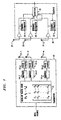
- FIG. 1 presents a block diagram of an arrangement with a transmitter having n transmitter antenna an a receiver with j receiving antenna.
- n 2
- FIG. 1 degenerates to FIG. 1 of the aforementioned 09/074,224 Alamouti et al application.
- an applied sequence of symbols c 1 , c 2 , c 3 , c 4 , c 5 , c 6 at the input of transmitter 10 results in the following sequence being sent by antennas 11 and 12.
- the transmission can be expressed by way of the matrix c 1 c 2 - c 2 * c 1 * , where the columns represent antennas, and the rows represent time of transmission.
- the corresponding received signal (ignoring the noise) is: Time: t t+T t+2T t+3T Antenna 11 h 1 c 1 + h 2 c 2 - h 1 ⁇ c 2 * + h 2 ⁇ c 1 * h 1 c 3 + h 2 c 4 - h 1 ⁇ c 4 * + h 2 ⁇ c 3 * ...
- h 1 is the channel coefficient from antenna 11 to antenna 21
- the signal r t j represents the signal received at time t by antenna j, and it is given by where n i j is the noise at time t at receiver antenna j , and it is assumed to be a independent, zero mean, complex, Gaussian random variable.
- the average energy of the symbols transmitted by each of the n antennas is 1/ n .
- a transmitter when it employs 8 antennas, it accumulates a frame of 8 bits and, with the beginning of the next frame, in the first time interval, the 8 antennas transmit bits c 1 , c 2 , c 3 , c 4 , c 5 , c 6 , c 7 , c 8 (the first row of symbols).
- the 8 antennas transmit bits -c 2 , c 1 , c 4 ,- c 3 , c 6 ,- c 5 , c 8 , c 7 (the second row of symbols), etc.
- a perusal of the above matrices reveals that the rows are mere permutations of the first row, with possible different signs.
- the different signs can be expressed by letting the sign of c i in the k -th row be denoted by ⁇ k ( i ).
- A be a p ⁇ q matrix with terms a ij
- B be any arbitrary matrix.
- the tensor product A ⁇ B is given by a 11 ⁇ B a 12 ⁇ B ⁇ a 1 ⁇ q ⁇ B a 21 ⁇ B a 22 ⁇ B ⁇ a 2 ⁇ q ⁇ B ⁇ ⁇ ⁇ ⁇ a p ⁇ 1 ⁇ B a p ⁇ 2 ⁇ B ⁇ a pq ⁇ B
- Lemma For any n there exists a Hurwitz-Radon family of matrices of size ⁇ ( n )-1 whose members are integer matrices in the set ⁇ -1,0,1 ⁇ .
- n 1 s 4 s +3
- n 2 s 4 s +4
- n 3 s 4 s +5
- n 4 s 4 s +6
- n 5 s 4 s +7 .
- matrix R is a Hurwitz-Radon integer family of size ⁇ (2)-1
- ⁇ R ⁇ I 2 , P ⁇ I 2 ,.., Q ⁇ I 2 ⁇ is a Hurwitz-Radon integer family of size ⁇ (2 2 )-1
- ( I 2 ⁇ R ⁇ I 2 , I 2 ⁇ P ⁇ R,Q ⁇ Q ⁇ R,P ⁇ Q ⁇ R,R ⁇ P ⁇ Q, R ⁇ P ⁇ , P,R ⁇ Q ⁇ I 2 ) is an integerHurwitz-Radon family of size ⁇ (2 3 )-1.
- ⁇ L 1 , L 2 , ⁇ L m ⁇ L m ⁇ is an integer Hurwitz-Radon family of k ⁇ k matrices
- equation (17) gives the transition from n 1 to n 2 .
- the coefficients l 1 i , l 2 i , ⁇ , l k i are positive integers.
- the above derivations can be employed for transmitting signals from n antennas using a generalized orthogonal design.
- a throughput of kb / p can be achieved.
- kb bits arrive at the encoder, which selects constellation symbols c 1 , c 2 , ⁇ c h .
- the diversity order is nm .
- the theory of space-time coding says that for a diversity order of nm , it is possible to transmit b bits per time slot, and this is the best possible. Therefore, the rate R is defined for this coding scheme is kb / pb, or k / p.
- the following presents an approach for constructing high rate linear processing designs with low decoding complexity and full diversity order. It is deemed advantageous to take transmitter memory into account, and that means that given the rate, R, and the number of transmitting antennas, n , it is advantageous to minimize the number of time slots in a frame, p.
- a ( R,n ) is the fundamental question of generalized design theory. The most interesting part of this question is the computation of A (1, n ) since the generalized designes of full rate are bandwidth efficient. To address the question the following construction is offered.
- This full rate generalized orthogonal design has entries of the form ⁇ c 1 , ⁇ c 2 , ⁇ , ⁇ c p .
- G 3 c 1 c 2 c 3 - c 2 c 1 - c 4 - c 3 c 4 c 1 - c 4 - c 3 c 2
- G 5 c 1 c 2 c 3 c 4 c 5 - c 2 c 1 c 4 - c 3 c 6 - c 3 - c 4 c 1 c 2 c 7 - c 4 c 3 - c 2 c 1 c 8 - c 5 - c 6 - c 7 - c 8 c 1 - c 6 c 5 - c 8 c 7 - c 8 c 1 - c 6 c 5 - c 8 c 7 - c 2 - c 7 c 8 c 5 - c 6 - c 7 c 8
- a design for a complex constellation is also possible.
- G c 3 c 1 c 2 c 3 - c 2 c 1 - c 4 - c 3 c 4 c 1 - c 4 - c 3 c 2 c 1 * c 2 * c 3 * - c 2 * c 1 * - c 4 * - c 3 * c 4 * c 1 * - c 4 * - c 3 * c 2 *
- G c 4 c 1 c 2 c 3 c 4 - c 2 c 1 - c 4 c 3 - c 3 c 4 c 1 - c 2 - c 4 - c 3 c 2 c 1 c 1 * c 2 * c 3 * c 4 * - c 2 * c 1 * - c 4 * - c 2 * c 1 * - c 4 * - c 2 * c 1 * - c 4 * c 3 * - c 3 * c 4 * c
- FIG. 1 depicts an arrangement where a transmitter includes an encoder 13 that is responsive to an applied steam of symbols.
- the encoder in most embodiments will include a memory for storing the incoming symbols.
- Those are processes in accordance with the above disclosure and, illustratively, are applied to n mappers 14.
- the mappers map the symbols onto a two dimensional constellation, for example, and apply the mapped symbols to n pulse shapers 15 which modulate the signals and apply them to transmitting antennas 11.
- the structure of transmitter 10 is illustrative only, and many other designs can be employed that would still realize the benefits of this invention.
- the transmitted signals are received by receiver 20, which includes j receiving antennas 21.
- the received signals are applied to detector 25, which detect signals in accordance with, for example, the detection scheme described above in connection with equations 9 and 10.
- Channel estimators 22 are conventional. Their function is to estimate the channel parameters for detector 25.
- the present disclosure concerns:
Landscapes
- Engineering & Computer Science (AREA)
- Computer Networks & Wireless Communication (AREA)
- Signal Processing (AREA)
- Radio Transmission System (AREA)
- Mobile Radio Communication Systems (AREA)
Applications Claiming Priority (4)
| Application Number | Priority Date | Filing Date | Title |
|---|---|---|---|
| US7661398P | 1998-03-03 | 1998-03-03 | |
| US09/186,907 US6088408A (en) | 1998-11-06 | 1998-11-06 | Decoding for generalized orthogonal designs for space-time codes for wireless communication |
| EP99908495A EP1060575B1 (fr) | 1998-03-03 | 1999-02-26 | Decodage de signaux codes espace-temps pour communication sans fil |
| EP07104452A EP1796285B1 (fr) | 1998-03-03 | 1999-02-26 | Transmission de signaux codés d'espace-temps pour communication sans fil |
Related Parent Applications (2)
| Application Number | Title | Priority Date | Filing Date |
|---|---|---|---|
| EP99908495.7 Division | 1999-02-26 | ||
| EP07104452.3 Division | 2007-03-20 |
Publications (2)
| Publication Number | Publication Date |
|---|---|
| EP2262123A2 true EP2262123A2 (fr) | 2010-12-15 |
| EP2262123A3 EP2262123A3 (fr) | 2011-01-19 |
Family
ID=26758288
Family Applications (2)
| Application Number | Title | Priority Date | Filing Date |
|---|---|---|---|
| EP99908495A Expired - Lifetime EP1060575B1 (fr) | 1998-03-03 | 1999-02-26 | Decodage de signaux codes espace-temps pour communication sans fil |
| EP10181645A Withdrawn EP2262123A3 (fr) | 1998-03-03 | 1999-02-26 | Transmission de signaux codés d'espace-temps pour communication sans fil |
Family Applications Before (1)
| Application Number | Title | Priority Date | Filing Date |
|---|---|---|---|
| EP99908495A Expired - Lifetime EP1060575B1 (fr) | 1998-03-03 | 1999-02-26 | Decodage de signaux codes espace-temps pour communication sans fil |
Country Status (8)
| Country | Link |
|---|---|
| EP (2) | EP1060575B1 (fr) |
| JP (1) | JP4245802B2 (fr) |
| KR (1) | KR100684483B1 (fr) |
| CN (1) | CN1292175A (fr) |
| BR (1) | BR9908389A (fr) |
| CA (1) | CA2321618C (fr) |
| DE (1) | DE69936044T2 (fr) |
| WO (1) | WO1999045657A1 (fr) |
Families Citing this family (17)
| Publication number | Priority date | Publication date | Assignee | Title |
|---|---|---|---|---|
| FI19992829A7 (fi) | 1999-12-30 | 2001-07-01 | Nokia Networks Oy | Datan lähetys radiojärjestelmässä lähettimeltä vastaanottimelle |
| EP1152548A1 (fr) | 2000-05-05 | 2001-11-07 | Lucent Technologies Inc. | Réseau sans fil à haut débit avec capacité de communication de données accrue |
| US7068628B2 (en) | 2000-05-22 | 2006-06-27 | At&T Corp. | MIMO OFDM system |
| US6654928B1 (en) | 2000-07-20 | 2003-11-25 | Nokia Mobile Phones Limited | Hybrid dimensional, spherical space-time coding and decoding apparatus, and associated method, for a communication system |
| WO2003105383A1 (fr) * | 2002-06-07 | 2003-12-18 | Linkair Communications, Inc. | Procede et appareil pour le codage de bloc a etalement spatio-temporel |
| KR100630108B1 (ko) | 2002-10-10 | 2006-09-27 | 삼성전자주식회사 | 공간-시간 블럭부호를 사용하여 송신 안테나 다이버시티를지원하는 송수신 장치 |
| JP4331563B2 (ja) * | 2002-10-10 | 2009-09-16 | 三星電子株式会社 | 空間−時間ブロック符号を用いて送信アンテナダイバシティを支援する送受信装置 |
| KR100640349B1 (ko) * | 2003-01-02 | 2006-10-30 | 삼성전자주식회사 | 3개의 송신 안테나들을 가지는 무선통신 시스템을 위한송수신 장치 |
| KR100605860B1 (ko) * | 2003-01-09 | 2006-07-31 | 삼성전자주식회사 | 4개의 송신 안테나를 사용하는 무선통신 시스템의 송신 장치 및 방법 |
| KR100557085B1 (ko) * | 2003-01-09 | 2006-03-03 | 삼성전자주식회사 | 적어도 3개의 송신 안테나들을 사용하는 무선통신시스템의 수신 장치 |
| FR2854995B1 (fr) | 2003-05-14 | 2005-07-29 | Nortel Networks Ltd | Modulateur et demodulateur a etalement de spectre |
| GB2406759B (en) * | 2003-10-02 | 2006-06-07 | Toshiba Res Europ Ltd | Signal decoding methods and apparatus |
| GB2409384B (en) * | 2003-12-18 | 2005-11-30 | Toshiba Res Europ Ltd | Maximum likelihood sequence estimation equaliser |
| CN100346578C (zh) * | 2004-01-07 | 2007-10-31 | 北京邮电大学 | 空时连续相位调制编码器的实现方法 |
| EP1768263B1 (fr) | 2004-05-26 | 2015-01-21 | NEC Corporation | Méthode de détection de signal mulitplexé spatialement et décodeur itératif d'espace temps l'utilisant |
| FR2873878A1 (fr) | 2004-08-02 | 2006-02-03 | Nortel Networks Ltd | Procede d'emission radio a diversite spatiale et emetteur radio mettant en oeuvre le procede |
| US8638885B2 (en) * | 2006-11-14 | 2014-01-28 | Intel Corporation | Space-time decoder and methods for decoding alamouti-encoded signals in high-doppler environments |
Citations (2)
| Publication number | Priority date | Publication date | Assignee | Title |
|---|---|---|---|---|
| US5479448A (en) | 1992-03-31 | 1995-12-26 | At&T Corp. | Method and apparatus for providing antenna diversity |
| US7422498B2 (en) | 2004-04-19 | 2008-09-09 | Burg Donald E | Ship with wave engulfing enhanced propulsors |
Family Cites Families (1)
| Publication number | Priority date | Publication date | Assignee | Title |
|---|---|---|---|---|
| US6185258B1 (en) * | 1997-09-16 | 2001-02-06 | At&T Wireless Services Inc. | Transmitter diversity technique for wireless communications |
-
1999
- 1999-02-26 WO PCT/US1999/004187 patent/WO1999045657A1/fr not_active Ceased
- 1999-02-26 EP EP99908495A patent/EP1060575B1/fr not_active Expired - Lifetime
- 1999-02-26 CA CA002321618A patent/CA2321618C/fr not_active Expired - Fee Related
- 1999-02-26 BR BR9908389-2A patent/BR9908389A/pt not_active Application Discontinuation
- 1999-02-26 KR KR1020007009707A patent/KR100684483B1/ko not_active Expired - Fee Related
- 1999-02-26 DE DE69936044T patent/DE69936044T2/de not_active Expired - Lifetime
- 1999-02-26 EP EP10181645A patent/EP2262123A3/fr not_active Withdrawn
- 1999-02-26 JP JP2000535103A patent/JP4245802B2/ja not_active Expired - Fee Related
- 1999-02-26 CN CN99803579A patent/CN1292175A/zh active Pending
Patent Citations (2)
| Publication number | Priority date | Publication date | Assignee | Title |
|---|---|---|---|---|
| US5479448A (en) | 1992-03-31 | 1995-12-26 | At&T Corp. | Method and apparatus for providing antenna diversity |
| US7422498B2 (en) | 2004-04-19 | 2008-09-09 | Burg Donald E | Ship with wave engulfing enhanced propulsors |
Non-Patent Citations (4)
| Title |
|---|
| "A New Bandwidth Efficient Transmit Antenna Modulation Diversity Scheme For Linear Digital Modulation", PROCEEDING OF THE 1993 IEEE INTERNATIONAL CONFERENCE ON COMMUNICATIONS (IICC '93), May 1993 (1993-05-01), pages 1630 - 1634 |
| A. WITTNEBEN: "Base Station Modulation Diversity for Digital SIMULCAST", PROCEEDING OF THE 1991 IEEE VEHICULAR TECHNOLOGY CONFERENCE (VTC 41 ST), May 1991 (1991-05-01), pages 848 - 853 |
| J. H. WINTERS: "The Diversity Gain of Transmit Diversity in Wireless Systems with Rayleigh Fading", PROCEEDING OF THE 1994 ICC/SUPERCOMM, NEW ORLEANS, vol. 2, May 1994 (1994-05-01), pages 1121 - 1125 |
| N. SESHADRI; J.H. WINTERS: "Two Signaling Schemes for Improving the Error Performance of FDD Transmission Systems Using Transmitter Antenna Diversity", PROCEEDING OF THE 1993 IEEE VEHICULAR TECHNOLOGY CONFERENCE (VTC 43RD), May 1993 (1993-05-01), pages 508 - 511 |
Also Published As
| Publication number | Publication date |
|---|---|
| CA2321618A1 (fr) | 1999-09-10 |
| JP2002506316A (ja) | 2002-02-26 |
| EP2262123A3 (fr) | 2011-01-19 |
| DE69936044D1 (de) | 2007-06-21 |
| EP1060575B1 (fr) | 2007-05-09 |
| KR20010041534A (ko) | 2001-05-25 |
| DE69936044T2 (de) | 2008-01-10 |
| EP1060575A1 (fr) | 2000-12-20 |
| KR100684483B1 (ko) | 2007-02-22 |
| CN1292175A (zh) | 2001-04-18 |
| CA2321618C (fr) | 2004-01-27 |
| WO1999045657A1 (fr) | 1999-09-10 |
| JP4245802B2 (ja) | 2009-04-02 |
| BR9908389A (pt) | 2000-10-31 |
Similar Documents
| Publication | Publication Date | Title |
|---|---|---|
| US6661856B1 (en) | Decoding for generalized orthogonal design for space-time codes for wireless communication | |
| US6430231B1 (en) | Generalized orthogonal designs for space-time codes for wireless communication | |
| EP1016228B1 (fr) | Technique d'emission en diversite pour communications sans fil | |
| EP0960487B1 (fr) | Detection par probabilite maximale a faible complexite de codes d'espace concatenes pour applications sans fil | |
| JP3633872B2 (ja) | 多重アンテナ構造におけるチャネルコーディングと空間ブロックコーディングの組合わせ | |
| EP1060575B1 (fr) | Decodage de signaux codes espace-temps pour communication sans fil | |
| EP1372271A2 (fr) | Technique d'émission en diversité pour communication sans fil | |
| EP1796285B1 (fr) | Transmission de signaux codés d'espace-temps pour communication sans fil | |
| MXPA00008490A (en) | Decoding of space-time coded signals for wireless communication |
Legal Events
| Date | Code | Title | Description |
|---|---|---|---|
| PUAI | Public reference made under article 153(3) epc to a published international application that has entered the european phase |
Free format text: ORIGINAL CODE: 0009012 |
|
| AC | Divisional application: reference to earlier application |
Ref document number: 1060575 Country of ref document: EP Kind code of ref document: P Ref document number: 1796285 Country of ref document: EP Kind code of ref document: P |
|
| AK | Designated contracting states |
Kind code of ref document: A2 Designated state(s): DE FR GB |
|
| PUAL | Search report despatched |
Free format text: ORIGINAL CODE: 0009013 |
|
| AK | Designated contracting states |
Kind code of ref document: A3 Designated state(s): DE FR GB |
|
| STAA | Information on the status of an ep patent application or granted ep patent |
Free format text: STATUS: THE APPLICATION IS DEEMED TO BE WITHDRAWN |
|
| 18D | Application deemed to be withdrawn |
Effective date: 20110830 |