EP2262127A2 - Kommunikationssystem und Verfahren zur Kanalschätzung und Strahlformung mit einer Mehrelement-Gruppenantenne - Google Patents
Kommunikationssystem und Verfahren zur Kanalschätzung und Strahlformung mit einer Mehrelement-Gruppenantenne Download PDFInfo
- Publication number
- EP2262127A2 EP2262127A2 EP10178417A EP10178417A EP2262127A2 EP 2262127 A2 EP2262127 A2 EP 2262127A2 EP 10178417 A EP10178417 A EP 10178417A EP 10178417 A EP10178417 A EP 10178417A EP 2262127 A2 EP2262127 A2 EP 2262127A2
- Authority
- EP
- European Patent Office
- Prior art keywords
- signals
- beamforming coefficients
- symbol
- subcarriers
- arrival
- Prior art date
- Legal status (The legal status is an assumption and is not a legal conclusion. Google has not performed a legal analysis and makes no representation as to the accuracy of the status listed.)
- Granted
Links
- 238000004891 communication Methods 0.000 claims abstract description 107
- 230000005540 biological transmission Effects 0.000 claims abstract description 16
- 238000000034 method Methods 0.000 claims description 36
- 230000000694 effects Effects 0.000 abstract description 5
- 238000005562 fading Methods 0.000 abstract description 5
- 239000011159 matrix material Substances 0.000 description 30
- 230000006870 function Effects 0.000 description 14
- 208000007944 Nodular Nonsuppurative Panniculitis Diseases 0.000 description 13
- 230000004044 response Effects 0.000 description 13
- 230000008054 signal transmission Effects 0.000 description 7
- 238000001228 spectrum Methods 0.000 description 6
- 238000000354 decomposition reaction Methods 0.000 description 5
- 238000011144 upstream manufacturing Methods 0.000 description 5
- 238000010586 diagram Methods 0.000 description 4
- 230000010363 phase shift Effects 0.000 description 3
- 238000005070 sampling Methods 0.000 description 2
- 230000003044 adaptive effect Effects 0.000 description 1
- 230000002457 bidirectional effect Effects 0.000 description 1
- 238000006243 chemical reaction Methods 0.000 description 1
- 239000013256 coordination polymer Substances 0.000 description 1
- 230000002950 deficient Effects 0.000 description 1
- 230000005404 monopole Effects 0.000 description 1
- 239000013598 vector Substances 0.000 description 1
Images


Classifications
-
- H—ELECTRICITY
- H04—ELECTRIC COMMUNICATION TECHNIQUE
- H04B—TRANSMISSION
- H04B7/00—Radio transmission systems, i.e. using radiation field
- H04B7/02—Diversity systems; Multi-antenna system, i.e. transmission or reception using multiple antennas
- H04B7/04—Diversity systems; Multi-antenna system, i.e. transmission or reception using multiple antennas using two or more spaced independent antennas
- H04B7/06—Diversity systems; Multi-antenna system, i.e. transmission or reception using multiple antennas using two or more spaced independent antennas at the transmitting station
- H04B7/0613—Diversity systems; Multi-antenna system, i.e. transmission or reception using multiple antennas using two or more spaced independent antennas at the transmitting station using simultaneous transmission
- H04B7/0615—Diversity systems; Multi-antenna system, i.e. transmission or reception using multiple antennas using two or more spaced independent antennas at the transmitting station using simultaneous transmission of weighted versions of same signal
- H04B7/0617—Diversity systems; Multi-antenna system, i.e. transmission or reception using multiple antennas using two or more spaced independent antennas at the transmitting station using simultaneous transmission of weighted versions of same signal for beam forming
-
- H—ELECTRICITY
- H04—ELECTRIC COMMUNICATION TECHNIQUE
- H04B—TRANSMISSION
- H04B7/00—Radio transmission systems, i.e. using radiation field
- H04B7/02—Diversity systems; Multi-antenna system, i.e. transmission or reception using multiple antennas
- H04B7/04—Diversity systems; Multi-antenna system, i.e. transmission or reception using multiple antennas using two or more spaced independent antennas
- H04B7/06—Diversity systems; Multi-antenna system, i.e. transmission or reception using multiple antennas using two or more spaced independent antennas at the transmitting station
- H04B7/0697—Diversity systems; Multi-antenna system, i.e. transmission or reception using multiple antennas using two or more spaced independent antennas at the transmitting station using spatial multiplexing
-
- H—ELECTRICITY
- H04—ELECTRIC COMMUNICATION TECHNIQUE
- H04B—TRANSMISSION
- H04B7/00—Radio transmission systems, i.e. using radiation field
- H04B7/02—Diversity systems; Multi-antenna system, i.e. transmission or reception using multiple antennas
- H04B7/04—Diversity systems; Multi-antenna system, i.e. transmission or reception using multiple antennas using two or more spaced independent antennas
- H04B7/08—Diversity systems; Multi-antenna system, i.e. transmission or reception using multiple antennas using two or more spaced independent antennas at the receiving station
- H04B7/0837—Diversity systems; Multi-antenna system, i.e. transmission or reception using multiple antennas using two or more spaced independent antennas at the receiving station using pre-detection combining
- H04B7/0842—Weighted combining
- H04B7/086—Weighted combining using weights depending on external parameters, e.g. direction of arrival [DOA], predetermined weights or beamforming
-
- H—ELECTRICITY
- H04—ELECTRIC COMMUNICATION TECHNIQUE
- H04L—TRANSMISSION OF DIGITAL INFORMATION, e.g. TELEGRAPHIC COMMUNICATION
- H04L25/00—Baseband systems
- H04L25/02—Details ; arrangements for supplying electrical power along data transmission lines
- H04L25/0202—Channel estimation
- H04L25/0224—Channel estimation using sounding signals
- H04L25/0226—Channel estimation using sounding signals sounding signals per se
-
- H—ELECTRICITY
- H04—ELECTRIC COMMUNICATION TECHNIQUE
- H04L—TRANSMISSION OF DIGITAL INFORMATION, e.g. TELEGRAPHIC COMMUNICATION
- H04L25/00—Baseband systems
- H04L25/02—Details ; arrangements for supplying electrical power along data transmission lines
- H04L25/0202—Channel estimation
- H04L25/024—Channel estimation channel estimation algorithms
- H04L25/0242—Channel estimation channel estimation algorithms using matrix methods
-
- H—ELECTRICITY
- H04—ELECTRIC COMMUNICATION TECHNIQUE
- H04L—TRANSMISSION OF DIGITAL INFORMATION, e.g. TELEGRAPHIC COMMUNICATION
- H04L27/00—Modulated-carrier systems
- H04L27/26—Systems using multi-frequency codes
- H04L27/2601—Multicarrier modulation systems
- H04L27/2647—Arrangements specific to the receiver only
- H04L27/2649—Demodulators
- H04L27/265—Fourier transform demodulators, e.g. fast Fourier transform [FFT] or discrete Fourier transform [DFT] demodulators
Definitions
- Embodiments of the present invention pertain to wireless communications, and some embodiments pertain to systems using symbol-modulated orthogonal subcarrier communications.
- Orthogonal frequency division multiplexing is an example of a multi-carrier transmission technique that uses symbol-modulated orthogonal subcarriers to transmit information within an available spectrum.
- the subcarriers When the subcarriers are orthogonal to one another, they may be spaced much more closely together within the available spectrum than, for example, the individual channels in a conventional frequency division multiplexing (FDM) system.
- FDM frequency division multiplexing
- a subcarrier may have a null at the center frequency of the other subcarriers. Orthogonality of the subcarriers may help reduce inter-subcarrier interference within the system.
- the subcarriers Before transmission, the subcarriers may be modulated with a low-rate data stream.
- the transmitted symbol rate of the symbols may be low, and thus the transmitted signal may be highly tolerant to multipath delay spread within the channel. For this reason, many modem digital communication systems are using symbol-modulated orthogonal subcarriers as a modulation scheme to help signals survive in environments having multipath reflections and/or strong interference.
- Communication systems that use symbol-modulated orthogonal subcarrier communications may have reduced channel capacity due to multipath fading and other channel conditions.
- apparatus and methods that increase channel capacity, improve channel equalization and/or reduce the effects of multipath fading, especially in systems using symbol-modulated orthogonal subcarrier communications.
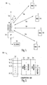
- FIG. 1 illustrates a wireless communication environment in which some embodiments of the present invention may be practiced.
- Communication environment 100 includes one or more wireless communication devices (WCD) 102 which may communicate with access point (AP) 104 over communication links 108, which may be bidirectional links.
- WCDs 102 may include, for example, personal digital assistants (PDAs), laptop and portable commuters with wireless communication capability, web tablets, wireless telephones, wireless headsets, pagers, instant messaging devices, MP3 players, digital cameras, and other devices that may receive and/or transmit information wirelessly.
- WCDs 102 may communicate with AP 104 using a multi-carrier transmission technique, such as an orthogonal frequency division multiplexing (OFDM) technique that uses orthogonal subcarriers to transmit information within an assigned spectrum.
- OFDM orthogonal frequency division multiplexing
- WCDs 102 and AP 104 may also implement one or more communication standards, such as one of the IEEE 802.11a, b or g standards, the Digital Video Broadcasting Terrestrial (DVB-T) broadcasting standard, or the High performance radio Local Area Network (HiperLAN) standard.
- LAN local area network
- WAN wireless area network
- AP 104 may be coupled with one or more networks 114, such as an intranet or the Internet, allowing WCDs 102 to access such networks.
- networks 114 such as an intranet or the Internet
- WCDs 102 may support duplex communications utilizing different spectrum for upstream and downstream communications, although this is not a requirement.
- upstream and downstream communications may share the same spectrum for communicating in both the upstream and downstream directions.
- FIG. 1 illustrates point-to-multipoint communications, embodiments of the present invention are suitable to both point-to-multipoint and point-to-point communications.
- a communication node e.g., access point 104 of a wireless local area network (WLAN) may utilize multi-element array antenna 106 to estimate angle-of-arrival 110 (e.g., theta ( ⁇ )) for communication signals received over links 108 from one or more signal sources (e.g., WCDs 102). Angle 110 may be measured relative to end-fire direction 116 of the antenna 106, although the scope of the invention is not limited in this respect.
- the signal sources may be wireless communication devices which communicate on symbol-modulated orthogonal subcarriers. Channel coefficients may be estimated from the angle-of-arrival for the one or more signal sources to increase channel capacity, improve channel equalization and/or reduce the effects of multipath fading.
- the channel coefficients may be generated from one symbol modulated on a plurality of subcarriers received by different elements of antenna 106.
- AP 104 may provide communications within a range of up to 500 feet, and even greater, for wireless communication devices, although the scope of the invention is not limited in this respect.
- beamforming coefficients may also be generated from the angle-of-arrival for improved reception and/or transmission of communication signals with the one or more signal sources using multi-element array antenna 106.
- the beamforming coefficients may be used to direct the reception and/or transmission of signals in a direction of the particular signal source.
- the angle-of-arrival may be estimated by sampling the response from the antenna elements of the array for at least one symbol at the subcarrier frequencies, although the scope of the invention is not limited in this respect.
- the sampled symbol may be a training symbol having a known value.
- the sampling may be performed on the same symbol at all subcarrier frequencies after demodulation by a fast Fourier transform (FFT) although the scope of the invention is not limited in this respect.
- FFT fast Fourier transform
- With beamforming frequency reuse may be realized using space-division multiple access techniques.
- Multi-element array antenna 106 may be a phased-array antenna comprising at least two directional or omnidirectional antenna elements 112.
- Elements 112 may comprise dipole antennas, monopole antennas, loop antennas, microstrip antennas or other type of antenna suitable for reception and/or transmission of RF signals which may be processed by AP 104.
- a beamformer may be used to control phasing between elements 112 to provide directional communications with WCDs 102.
- the phasing may be controlled at baseband, although the scope of the invention is not limited in this respect.
- FIG. 2 is a block diagram of a communication node in accordance with some embodiments of the present invention.
- Communication node 200 may be suitable for use as AP 104 ( FIG. 1 ), although other communication nodes may also be suitable.
- communication node 200 may also be suitable for use as one or more of WCDs 102 ( FIG. 1 ), although the scope of the invention is not limited in this respect.
- Communication node 200 receives and/or transmits radio frequency (RF) communications with multi-element array antenna 202.
- RF signals received from antenna 202 may be converted to baseband signals and eventually to data signals comprising a bit stream by transceiver 204.
- Transceiver 204 may also convert data signals comprising a bit stream to baseband signals and RF signals for transmission by antenna 202.
- Communication node 200 may also include signal separator 206 to separate received and transmitted communication signals.
- Communication node 200 may also include data processing portion 208 to process data signals received through transceiver 204 and generate data signals for transmission by transceiver 204.
- Antenna 202 may comprise a plurality of antenna elements 212, which may correspond to antenna elements 112 ( FIG. 1 ).
- signal separator 206 is illustrated as a separate element of node 200, the present invention is not limited in this respect. In some embodiments, signal separator 206 may be part of antenna 202, while in other embodiments, antenna 202 may comprise one set of antenna elements for transmission of signals, and another set of antenna elements for reception of signals eliminating the need for signal separator 206.
- communication node 200 may include interfaces 210 to wireline devices and wireline networks, such as to a personal computer, a server, or the Internet, for example. In these embodiments, communication node 200 may facilitate communications between WCDs 102 ( FIG. 1 ) and these wireline devices and/or networks.
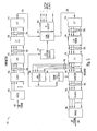
- FIG. 3 illustrates a block diagram of a transceiver in accordance with some embodiments of the present invention.
- Transceiver 300 may be suitable for use as transceiver 204 ( FIG. 2 ) although other transceiver configurations may also be suitable.
- Transceiver 300 may include RF circuitry 302 to receive a signal from a signal source through a multi-element antenna having a plurality of antenna elements. The signal may comprise a plurality of subcarriers modulated with at least one symbol.
- Transceiver 300 may also include angle-of-arrival (AOA) estimator 304 to estimate an angle-of-arrival for a signal source from a subcarrier level of the symbol received by at least two of the antenna elements.
- AOA angle-of-arrival
- Transceiver 300 may also include channel coefficient generator 306 to generate channel coefficients for communications received from the signal source based on the angle-of-arrival. The channel coefficients may compensate for at least some of the channel effects between a signal source and the access point. Transceiver 300 may also include channel equalizer 308 which may be responsive to the channel coefficients to provide equalized frequency-domain symbol-modulated subcarriers 310 resulting in improved reception.
- channel coefficient generator 306 to generate channel coefficients for communications received from the signal source based on the angle-of-arrival. The channel coefficients may compensate for at least some of the channel effects between a signal source and the access point.
- Transceiver 300 may also include channel equalizer 308 which may be responsive to the channel coefficients to provide equalized frequency-domain symbol-modulated subcarriers 310 resulting in improved reception.
- transceiver 300 may further include beamformer coefficient generator 312 to generate beamforming coefficients for elements of the multi-element antenna based on the angle-of-arrival. The beamforming coefficients may be used to help direct the reception and/or transmission of signals in a direction of a particular signal source.
- transceiver 300 may further include beamformer 314.
- Beamformer 314 may change the directionality of the antenna based on the beamforming coefficients, and in some embodiments, beamformer 314 may change phasing of received and/or transmitted signals. In some embodiments, beamforming may be done prior to conversion to corresponding RF signals by RF circuitry 302 and transmission of the signals by the elements of the multi-element antenna.
- beamformer 314 may change the directionality of the antenna by changing the phasing of baseband-level signals that comprise a plurality of symbol-modulated subcarriers for use in generating and/or receiving an orthogonal-frequency division multiplexed signal by RF circuitry 302 for transmission and/or reception by a multi-element antenna.
- frequency reuse may be realized using space-division multiple access techniques.
- angle-of-arrival estimator 304 may include one or more processors and memory to generate an initial matrix (e.g., X) comprising demodulated pilot subcarriers for a symbol provided by FFT 328 corresponding to each of the antenna elements.
- 'D' may represent a diagonal matrix having elements corresponding to the pilot subcarriers of the symbol
- 'N' may represent an uncorrelated noise matrix.
- the processor and memory may use a search function to identify a peak corresponding to the angle-of-arrival. The search function may be based on a decomposition of the response matrix. This is described in more detail below.
- FIG. 4 illustrates a time-frequency structure of an orthogonal frequency division multiplexed packet suitable for use with some embodiments of the present invention.
- Time-frequency structure 400 is an example of a packet in accordance with the IEEE 802.11 (a) standard; however, other time-frequency structures for packets may be equally suitable for use with some embodiments of the present invention.
- symbols having known training values are crosshatched/shaded.
- Structure 400 illustrates a packet starting with ten short training symbols 402 modulated on twelve subcarriers 404. These symbols may contain known pilot subcarriers.
- Short training symbols 402 are followed by two long training symbols 406 which are followed by data symbols 408.
- Data symbols 408 may include four pilot subcarriers 410.
- angle-of-arrival estimator 304 may estimate the angle-of-arrival based the antenna response for subcarriers 404 for one of training symbols 402 or based on one of training symbols 406, although the scope of the invention is not limited in this respect.
- a training symbol may have known training values.
- channel equalizer 308 FIG. 3
- RF receive circuitry 302 receives signals through a multi-element antenna, and generates serial symbol stream 320 representing symbols.
- a packet may include short training symbols 402 ( FIG. 4 ) and long training symbols 406 ( FIG. 4 ) followed by data symbols 408 ( FIG. 4 ).
- the received signal may have a carrier frequency ranging between 5 and 6 GHz, although embodiments of the present invention are equally suitable to carrier frequencies, for example, ranging between 2 and 20 GHz, and even greater.
- a symbol-modulated signal may include up to a hundred or more subcarriers.
- the short training symbols may be transmitted on a portion of the subcarriers, and data symbols may contain one or more known pilot subcarriers although this is not a requirement.
- the long training symbols may have a duration of approximately 4 microseconds and the short training symbols may have a duration of approximately one microsecond.
- the signals may be infrared (IR) signals.
- the receiver portion of transceiver 300 may include serial to parallel (S/P) converter 322 to convert a symbol of serial symbol stream 320 into parallel groups of time-domain samples 324.
- Cyclic-redundancy prefix (C/P) element 326 removes a cyclic-redundancy prefix from each symbol.
- Fast Fourier Transform (FFT) element 328 performs an FFT on parallel groups of time-domain samples 330 to generate frequency-domain symbol-modulated subcarriers 332 for use by equalizer 308 and angle-of-arrival estimator 304.
- S/P serial to parallel
- FFT Fast Fourier Transform
- Angle-of-arrival estimator 304 may generate an angle-of-arrival estimate for a signal source which may be used by channel coefficient generator 306 for generating channel coefficients for use by equalizer 308 for improved demodulation of the subcarriers.
- a channel estimator (not illustrated) may be used, in addition to generator 306, to generate channel estimates for use by equalizer 308.
- Equalizer 308 may perform a channel equalization on frequency-domain symbol-modulated subcarriers 332 provided by FFT element 328. Equalizer 308 may generate equalized frequency-domain symbol-modulated subcarriers 310 using the channel coefficients provided by channel coefficient generator 306. For example, equalization in the frequency domain may be performed by division of the frequency domain subcarriers 332 with complex values that represent the channel estimation. Accordingly, the magnitudes of equalized frequency-domain symbol-modulated subcarriers 332 may be normalized and the phases of equalized frequency-domain symbol-modulated subcarriers 310 may be aligned to a zero origin to allow for further processing by demapper 334.
- Equalized frequency-domain symbol-modulated subcarriers 310 may be demapped by demapper 334 to produce a plurality of parallel symbols.
- Demapper 334 may demap the parallel symbols in accordance with a particular modulation order in which the transmitter modulated the subcarriers.
- Modulation orders may include binary phase shift keying (BPSK), which communicates one bit per symbol, quadrature phase shift keying (QPSK), which communicates two bits per symbol, 8-PSK, which communicates three bits per symbol, 16-quadrature amplitude modulation (16-QAM), which communicates four bits per symbol, 32-QAM, which communicates five bits per symbol, and 64-QAM, which communicates six bits per symbol.
- BPSK binary phase shift keying
- QPSK quadrature phase shift keying
- 8-PSK which communicates three bits per symbol
- 16-QAM 16-quadrature amplitude modulation
- 32-QAM which communicates five bits per symbol
- 64-QAM which communicates six bits per symbol
- Modulation orders may also include differentially-coded star QAM (DSQAM). Modulation orders with lower and even higher communication rates may also be used.
- the parallel symbols from demapper 334 may be converted from a parallel form to a serial stream by parser 336, which may perform a de-interleaving operation on the serial stream. Parser 336 generates decoded serial bit stream 338 for use by data processing elements (not illustrated).
- the transmitter portion of transceiver 300 may include parser 342 to encode serial bit-stream 340 to generate parallel symbols.
- Mapper 344 maps the parallel symbols to frequency-domain symbol-modulated subcarriers 346.
- IFFT element 348 performs an inverse fast Fourier transform (IFFT) on frequency-domain symbol-modulated subcarriers 346 to generate parallel groups of time-domain samples 350.
- CP circuit 352 adds a cyclic-redundancy prefix to each symbol, and parallel-to-serial (P/S) circuit 354 converts the parallel groups of time-domain samples 356 to serial symbol stream 358 for RF circuitry 302.
- the length of the cyclic-redundancy prefix is greater than the length of intersymbol interference.
- communication node 200 ( FIG. 2 ) and transceiver 300 are illustrated as having several separate functional circuit elements, one or more of the functional elements may be combined and may be implemented by combinations of software-configured elements, such as processing elements including digital signal processors (DSPs), and/or other hardware elements and software.
- processing elements including digital signal processors (DSPs), and/or other hardware elements and software.
- circuit elements may comprise one or more processing elements such as microprocessors, DSPs, application specific integrated circuits (ASICs), and combinations of various hardware and logic circuitry for performing at least the functions described herein.
- FIG. 5 is a flow chart of a communication procedure in accordance with some embodiments of the present invention.
- Communication procedure 500 may be performed by a communication node, such as AP 104 ( FIG. 1 ) although other communication nodes may also be suitable for performing procedure 500.
- communication procedure 500 may be performed by communication devices, such as WCDs 102 ( FIG. 1 ).
- WCDs 102 FIG. 1
- the individual operations of procedure 500 are illustrated and described as separate operations, one or more of the individual operations may be performed concurrently and nothing requires that the operations be performed in the order illustrated.
- a signal comprising at least one symbol of a data packet comprising symbol-modulated subcarriers is received through a multi-element antenna from a signal source.
- an FFT may be performed on parallel groups of time-domain samples that represent the symbol as received by the elements of the multi-element antenna.
- the FFT may generate frequency-domain symbol-modulated subcarriers for each antenna element.
- the symbol may be a training symbol having known training values.
- an angle-of-arrival estimate is generated for the signal source. The angle-of-arrival may be relative to an end-fire direction of the multi-element antenna.
- the angle-of-arrival may be estimated based on the antenna response for the antenna elements for more than one subcarrier frequency of the symbol, although the scope of the invention is not limited in this respect.
- channel coefficients may be generated from the angle-of-arrival estimate, and in operation 510, the channel coefficients may be used for equalization of symbols, including data symbols, subsequently received from the signal source.
- beamforming coefficients may be generated based on the angle-of-arrival, and in operation 514, a communication signal comprising symbol-modulated subcarriers may be directionally transmitted to the signal source (e.g., in a direction of the signal source) using the beamforming coefficients.
- a communication signal comprising symbol-modulated subcarriers may be directionally received from the signal source using the beamforming coefficients.
- procedure 500 may be repeated or performed concurrently for one or more of a plurality of signal sources.
- angles-of-arrival may be individually estimated for the different signal sources, and channel and beamforming coefficients may be generated for the different signal sources and used for communicating with the signal sources. Accordingly, increased channel capacity, improved channel equalization and/or reduced the effects of multipath fading may be achieved, although the scope of the invention is not limited in this respect.
- an angle-of-arrival may be estimated by angle-of-arrival estimator 304 ( FIG. 2 ) and channel coefficients may be generated by channel coefficient generator 306 ( FIG. 3 ) as illustrated in the following example.
- angle-of-arrival estimator 304 FIG. 2
- channel coefficients may be generated by channel coefficient generator 306 ( FIG. 3 ) as illustrated in the following example.
- the signals may be collected after demodulation by an FFT in the form of matrix, which may be described by the following equations.
- X AD + N
- X is a matrix in which the i th column may correspond to the antenna-array response to the i th subcarrier.
- D is a diagonal matrix whose elements may correspond to the known pilot symbols scaled by channel coefficients along with the phase shift.
- A is an array-response matrix for the subcarrier frequencies.
- m corresponds to the m th symbol.
- N may be a spatially and temporally uncorrelated noise matrix.
- a matrix B may be formed.
- B A ⁇ x ⁇ where ⁇ ⁇ 0 , 2 ⁇ ⁇ .
- the size of matrix B may be N ( Q +1), where N ⁇ ( Q +1).
- the ⁇ true estimate can be found from the following QR-decomposition and search function.
- r Q,Q ( ⁇ ) is the Q -th diagonal element of the upper triangular matrix R ( ⁇ ) .
- the search function G( ⁇ ) may have J-highest peaks that may correspond to the angle-of arrival estimates, ⁇ 1 ,... ⁇ J of J-sources.
- the estimates ( ⁇ 1 ,.... ⁇ J ) may be obtained from processing of four pilot subcarriers that are spaced quite apart in the frequency spectrum. Such a property may provide a good approximation of the angle-of-arrival corresponding to the complete set of subcarriers in the OFDM. In other words the estimates may correspond to angle-of-arrival of broadband signal sources.
- ⁇ ( ⁇ 1 ,.... ⁇ J )
- the estimation of angular information ⁇ of a signal source may be performed for only one sample.
- the angular estimate ⁇ may be repeatedly used for each subset of subcarrier matrices and accordingly the channel estimates for entire subcarrier channels may be found.
- beamforming in the direction ⁇ estimate is performed to increase the channel capacity.
- frequency reuse may be realized using space-division multiple access techniques.
- the beamforming may be used for both reception and transmission.
- An alternative embodiment provides for a communication node comprising: an angle-of-arrival estimator to estimate an angle-of-arrival for a received signal from a subcarrier level of at least one symbol received by at least two elements of a multi-element antenna, the received signal comprising a plurality of subcarriers modulated with the at least one symbol; and a channel coefficient generator to generate channel coefficients from the estimated angle-of-arrival for processing subsequent symbols.
- a preferred embodiment of the communication node further comprises a channel equalizer responsive to the channel coefficients to provide equalized frequency-domain symbol- modulated subcarriers.
- the at least one symbol used by the angle-of-arrival estimator comprises a training symbol having a known training value
- the channel equalizer provides equalized frequency-domain symbol-modulated subcarriers for subsequent data symbols of a packet received from a signal source.
- Another preferred embodiment of the communication further comprises a beamformer coefficient generator to generate beamforming coefficients for elements of the multi-element antenna based on the angle-of-arrival.
- Another preferred embodiment of the communication further comprises a beamformer to change directionality of the antenna at based on the beamforming coefficients for directional reception and transmission of signals by the multi-element antenna in a direction of a signal source.
- Another preferred embodiment of the communication further comprises RF circuitry, wherein the beamformer changes the directionality of the antenna by changing phasing of baseband-level signals that comprise a plurality of symbol-modulated subcarriers for use in receiving and transmitting an orthogonal-frequency division multiplexed signal by the RF circuitry for reception and transmission by the antenna.
- the received signal comprises an orthogonal-frequency division multiplexed signal comprising plurality of symbol- modulated substantially orthogonal subcarriers.
- Another preferred embodiment of the communication node provides that a plurality of signals are received from a corresponding plurality of signal sources, and the angle-of-arrival estimator estimates an angle-of-arrival for different signal sources from at least one symbol received from the signal sources through elements of the antenna.
- the communication node comprises an access point of a wireless local area network and at least some signal sources comprise portable wireless communication devices.
- Another preferred embodiment of the communication node further comprises Fast-Fourier Transform (FFT) circuitry to perform an FFT on at least one parallel group of time-domain samples that comprise the at least one symbol of pilot subcarriers to generate frequency-domain symbol-modulated subcarriers for use by the angle-of-arrival estimator in estimating the angle-of-arrival.
- FFT Fast-Fourier Transform
- the communication node is a wireless access point for providing communications within a range of up to approximately 500 feet for a plurality of wireless communication devices.
- a further alternative embodiment provides for a method comprising: receiving a signal through a multi-element antenna, the signal comprising a plurality of subcarriers modulated with at least one symbol; estimating an angle-of-arrival for the signal from a subcarrier level of the at least one symbol received by at least two elements of the antenna; and generating channel coefficients from the estimated angle-of-arrival for processing subsequent symbols of the signal.
- a preferred embodiment of the method further comprises equalizing frequency-domain symbol-modulated subcarriers using the channel coefficients to provide equalized frequency-domain symbol-modulated subcarriers.
- the at least one symbol used to estimate the angle-of-arrival comprises a training symbol having a known value
- equalizing comprises providing equalized frequency-domain symbol-modulated subcarriers for subsequent data symbols of a packet.
- Another preferred embodiment of the method further comprises generating beamforming coefficients for elements of the multi-element antenna based on the angle-of-arrival.
- Another preferred embodiment of the method further comprises changing directionality of the antenna using the beamforming coefficients for directional reception and transmission of signals by the multi-element antenna.
- Another preferred embodiment of the method further comprises performing an FFT on at least one parallel group of time-domain samples that comprise at least one symbol of pilot subcarriers to generate frequency-domain symbol-modulated subcarriers for use in estimating the angle-of-arrival.
- Another alternative embodiment provides for a communication system comprising: at least one wireless communication device; and an access point having a multi-element antenna to communicate with the at least one wireless communication device using symbol-modulated orthogonal subcarrier communication signals, and an angle-of-arrival estimator to estimate an angle-of-arrival for the at least one wireless communication device for use in processing subsequent symbols of the communication signals received from the at least one wireless communication device.
- a preferred embodiment of the communication system provides that the angle-of-arrival estimator estimates the angle-of-arrival from a subcarrier level of at least one symbol received by at least two of elements of the multi-element antenna.
- the access point further comprises: a channel coefficient generator to generate channel coefficients based on the estimated angle-of-arrival for processing subsequent symbols of a packet received from the wireless communication device; and a beamformer coefficient generator to generate beamforming coefficients for elements of the multi-element antenna based on the angle-of-arrival for directional communications with the wireless communication device.
- the access point further comprises: a beamformer to change phasing of baseband-level signals based on beamforming coefficients for reception and transmission of signals by the elements of the multi-element antenna in a direction of the wireless communication device; and RF circuitry, wherein the beamformer changes the phasing of baseband-level signals that comprise a plurality of symbol-modulated subcarriers for use in receiving and transmitting an orthogonal-frequency division multiplexed signal by the RF circuitry for directional reception and transmission by the antenna.
- Yet another alternative embodiment provides a communication system comprising: an angle-of-arrival estimator to estimate an angle-of-arrival for a received signal from a subcarrier level of at least one symbol received by at least two elements of a multi-element antenna, the received signal being received from a wireless communication device and comprising a plurality of subcarriers modulated with the at least one symbol; a channel coefficient generator to generate channel coefficients from the estimated angle-of-arrival for processing subsequent symbols; and a network interface to facilitate communications between the wireless communication device and one or more wireline networks.
- a preferred embodiment of this communication system further comprises a channel equalizer responsive to the channel coefficients to provide equalized frequency-domain symbol-modulated subcarriers, wherein the at least one symbol used by the angle-of-arrival estimator comprises a training symbol having a known training value, and wherein the channel equalizer provides equalized frequency-domain symbol-modulated subcarriers for subsequent data symbols of a packet received from the wireless communication device.
- Another preferred embodiment of this communication system further comprises: a beamformer coefficient generator to generate beamforming coefficients for elements of the multi-element antenna based on the angle-of-arrival; and a beamformer to change directionality of the antenna at based on the beamfonning coefficients for directional reception and transmission of signals by the multi-element antenna in a direction of the wireless communication device.
- Another alternative embodiment provides for an article comprising a storage medium having stored thereon instructions, that when executed by a computing platform, result in: receiving a signal through a multi-element antenna, the signal comprising a plurality of subcarriers modulated with at least one symbol; estimating an angle-of-arrival for the signal from a subcarrier level of the at least one symbol received by at least two elements of the antenna; and generating channel coefficients from the estimated angle-of-arrival for processing subsequent symbols of the signal.
- a preferred embodiment of the article provides that the instructions when executed by the computing platform additionally result in equalizing frequency-domain symbol-modulated subcarriers using the channel coefficients to provide equalized frequency-domain symbol- modulated subcarriers.
- the at least one symbol used to estimate the angle-of-arrival comprises a training symbol having a known value
- the instructions when executed by the computing platform additionally result in: providing equalized frequency-domain symbol-modulated subcarriers for subsequent data symbols of a packet; and generating beamforming coefficients for elements of the multi-element antenna based on the angle-of-arrival.
Landscapes
- Engineering & Computer Science (AREA)
- Computer Networks & Wireless Communication (AREA)
- Signal Processing (AREA)
- Power Engineering (AREA)
- Physics & Mathematics (AREA)
- Mathematical Physics (AREA)
- Radio Transmission System (AREA)
- Noise Elimination (AREA)
- Mobile Radio Communication Systems (AREA)
Applications Claiming Priority (3)
| Application Number | Priority Date | Filing Date | Title |
|---|---|---|---|
| US10/654,037 US7453946B2 (en) | 2003-09-03 | 2003-09-03 | Communication system and method for channel estimation and beamforming using a multi-element array antenna |
| EP04786582.9A EP1671396B1 (de) | 2003-09-03 | 2004-08-25 | Kommunikationssystem und verfahren zur kanalschätzung und strahlformung mit einer mehrelement-gruppenantenne |
| PCT/US2004/027741 WO2005024995A2 (en) | 2003-09-03 | 2004-08-25 | Communication system and method for channel estimation and beamforming using a multi-element array antenna |
Related Parent Applications (3)
| Application Number | Title | Priority Date | Filing Date |
|---|---|---|---|
| EP04786582.9A Division EP1671396B1 (de) | 2003-09-03 | 2004-08-25 | Kommunikationssystem und verfahren zur kanalschätzung und strahlformung mit einer mehrelement-gruppenantenne |
| EP04786582.9A Division-Into EP1671396B1 (de) | 2003-09-03 | 2004-08-25 | Kommunikationssystem und verfahren zur kanalschätzung und strahlformung mit einer mehrelement-gruppenantenne |
| EP04786582.9 Division | 2004-08-25 |
Publications (3)
| Publication Number | Publication Date |
|---|---|
| EP2262127A2 true EP2262127A2 (de) | 2010-12-15 |
| EP2262127A3 EP2262127A3 (de) | 2012-11-21 |
| EP2262127B1 EP2262127B1 (de) | 2019-05-08 |
Family
ID=34217999
Family Applications (2)
| Application Number | Title | Priority Date | Filing Date |
|---|---|---|---|
| EP10178417.1A Expired - Lifetime EP2262127B1 (de) | 2003-09-03 | 2004-08-25 | Kommunikationssystem und Verfahren zur Kanalschätzung und Strahlformung mit einer Mehrelement-Gruppenantenne |
| EP04786582.9A Expired - Lifetime EP1671396B1 (de) | 2003-09-03 | 2004-08-25 | Kommunikationssystem und verfahren zur kanalschätzung und strahlformung mit einer mehrelement-gruppenantenne |
Family Applications After (1)
| Application Number | Title | Priority Date | Filing Date |
|---|---|---|---|
| EP04786582.9A Expired - Lifetime EP1671396B1 (de) | 2003-09-03 | 2004-08-25 | Kommunikationssystem und verfahren zur kanalschätzung und strahlformung mit einer mehrelement-gruppenantenne |
Country Status (5)
| Country | Link |
|---|---|
| US (3) | US7453946B2 (de) |
| EP (2) | EP2262127B1 (de) |
| CN (2) | CN102158269B (de) |
| TW (1) | TWI247497B (de) |
| WO (1) | WO2005024995A2 (de) |
Cited By (2)
| Publication number | Priority date | Publication date | Assignee | Title |
|---|---|---|---|---|
| WO2014091274A1 (en) * | 2012-12-10 | 2014-06-19 | Intel Corporation | Modular antenna array with rf and baseband beamforming |
| US9768501B2 (en) | 2013-01-21 | 2017-09-19 | Intel Corporation | Apparatus, system and method of steering an antenna array |
Families Citing this family (87)
| Publication number | Priority date | Publication date | Assignee | Title |
|---|---|---|---|---|
| US7453946B2 (en) * | 2003-09-03 | 2008-11-18 | Intel Corporation | Communication system and method for channel estimation and beamforming using a multi-element array antenna |
| US7720509B2 (en) * | 2003-10-02 | 2010-05-18 | Toshiba America Research, Inc. | Harmonized adaptive arrays |
| US7158814B2 (en) * | 2004-06-10 | 2007-01-02 | Interdigital Technology Corporation | Method and system for utilizing smart antennas establishing a backhaul network |
| US7619964B2 (en) * | 2004-07-08 | 2009-11-17 | Nokia Corporation | High doppler channel estimation for OFD multiple antenna systems |
| US9002299B2 (en) * | 2004-10-01 | 2015-04-07 | Cisco Technology, Inc. | Multiple antenna processing on transmit for wireless local area networks |
| US9491638B2 (en) * | 2005-03-09 | 2016-11-08 | Xirrus, Inc. | Wireless access point array |
| US8769046B2 (en) * | 2005-03-23 | 2014-07-01 | Qualcomm Incorporated | Methods and apparatus for using multiple wireless links with a wireless terminal |
| US8363577B2 (en) * | 2005-05-13 | 2013-01-29 | Qualcomm Incorporated | Low complexity beamforming for multiple antenna systems |
| US7489670B2 (en) | 2005-12-27 | 2009-02-10 | Celeno Communications Ltd. | Device, system and method of uplink/downlink communication in wireless network |
| US20070153760A1 (en) | 2005-12-29 | 2007-07-05 | Nir Shapira | Method, apparatus and system of spatial division multiple access communication in a wireless local area network |
| US7656965B2 (en) * | 2005-12-29 | 2010-02-02 | Celeno Communications (Israel) Ltd. | Method of secure WLAN communication |
| US9071435B2 (en) | 2005-12-29 | 2015-06-30 | Celeno Communications Ltd. | System and method for tuning transmission parameters in multi-user multiple-input-multiple-output systems with aged and noisy channel estimation |
| US7751353B2 (en) * | 2005-12-29 | 2010-07-06 | Celeno Communications (Israel) Ltd. | Device, system and method of securing wireless communication |
| US7672400B2 (en) * | 2005-12-29 | 2010-03-02 | Celeno Communications (Israel) Ltd. | Method of secure WLAN communication |
| US20070153754A1 (en) * | 2005-12-29 | 2007-07-05 | Nir Shapira | Method, apparatus and system of spatial division multiple access communication in a wireless local area network |
| US7570624B2 (en) * | 2005-12-29 | 2009-08-04 | Celeno Communications (Israel) Ltd. | Device, system and method of uplink/downlink communication in wireless network |
| DE602006004175D1 (de) * | 2006-04-12 | 2009-01-22 | Ntt Docomo Inc | Gerät zur Bestimmung der Keulenrichtung |
| US8787841B2 (en) * | 2006-06-27 | 2014-07-22 | Qualcomm Incorporated | Method and system for providing beamforming feedback in wireless communication systems |
| JP4907721B2 (ja) * | 2006-12-07 | 2012-04-04 | インターデイジタル テクノロジー コーポレーション | トレーニング信号および情報ビットを割り当てるための無線通信方法および装置 |
| US8380133B2 (en) * | 2009-05-11 | 2013-02-19 | Nec Laboratories America, Inc. | Beamforming methods and systems employing measured power at a receiver to perform channel estimation |
| EP2264960B1 (de) | 2009-06-19 | 2014-10-01 | Alcatel Lucent | Verfahren und Verarbeitungsanordnung zur gemeinsamen Verarbeitung von Uplink-Daten |
| US8073399B2 (en) * | 2009-06-23 | 2011-12-06 | Lockheed Martin Corporation | Device and method for matrixed adaptive equalizing for communication receivers configured to an antenna array |
| US8437245B2 (en) * | 2009-08-31 | 2013-05-07 | Texas Instruments Incorporated | Wireless network system |
| US8537928B2 (en) | 2010-10-08 | 2013-09-17 | Nec Laboratories America, Inc. | Channel estimation methods and systems based on power measurement at receivers |
| US8811522B2 (en) | 2012-05-29 | 2014-08-19 | Magnolia Broadband Inc. | Mitigating interferences for a multi-layer MIMO system augmented by radio distribution network |
| US8861635B2 (en) | 2012-05-29 | 2014-10-14 | Magnolia Broadband Inc. | Setting radio frequency (RF) beamformer antenna weights per data-stream in a multiple-input-multiple-output (MIMO) system |
| US8767862B2 (en) | 2012-05-29 | 2014-07-01 | Magnolia Broadband Inc. | Beamformer phase optimization for a multi-layer MIMO system augmented by radio distribution network |
| US8619927B2 (en) | 2012-05-29 | 2013-12-31 | Magnolia Broadband Inc. | System and method for discrete gain control in hybrid MIMO/RF beamforming |
| US8837650B2 (en) | 2012-05-29 | 2014-09-16 | Magnolia Broadband Inc. | System and method for discrete gain control in hybrid MIMO RF beamforming for multi layer MIMO base station |
| US8971452B2 (en) * | 2012-05-29 | 2015-03-03 | Magnolia Broadband Inc. | Using 3G/4G baseband signals for tuning beamformers in hybrid MIMO RDN systems |
| US8644413B2 (en) | 2012-05-29 | 2014-02-04 | Magnolia Broadband Inc. | Implementing blind tuning in hybrid MIMO RF beamforming systems |
| US8842765B2 (en) | 2012-05-29 | 2014-09-23 | Magnolia Broadband Inc. | Beamformer configurable for connecting a variable number of antennas and radio circuits |
| US9154204B2 (en) | 2012-06-11 | 2015-10-06 | Magnolia Broadband Inc. | Implementing transmit RDN architectures in uplink MIMO systems |
| US9007272B2 (en) * | 2012-07-19 | 2015-04-14 | Tensorcom, Inc. | Method and apparatus for the alignment of a 60 GHz endfire antenna |
| US10433044B2 (en) * | 2012-08-02 | 2019-10-01 | Ronald Pong | Headphones with interactive display |
| US9343808B2 (en) | 2013-02-08 | 2016-05-17 | Magnotod Llc | Multi-beam MIMO time division duplex base station using subset of radios |
| US8797969B1 (en) | 2013-02-08 | 2014-08-05 | Magnolia Broadband Inc. | Implementing multi user multiple input multiple output (MU MIMO) base station using single-user (SU) MIMO co-located base stations |
| US20140226740A1 (en) | 2013-02-13 | 2014-08-14 | Magnolia Broadband Inc. | Multi-beam co-channel wi-fi access point |
| US8774150B1 (en) | 2013-02-13 | 2014-07-08 | Magnolia Broadband Inc. | System and method for reducing side-lobe contamination effects in Wi-Fi access points |
| US8989103B2 (en) | 2013-02-13 | 2015-03-24 | Magnolia Broadband Inc. | Method and system for selective attenuation of preamble reception in co-located WI FI access points |
| US9155110B2 (en) | 2013-03-27 | 2015-10-06 | Magnolia Broadband Inc. | System and method for co-located and co-channel Wi-Fi access points |
| US9100968B2 (en) | 2013-05-09 | 2015-08-04 | Magnolia Broadband Inc. | Method and system for digital cancellation scheme with multi-beam |
| US9425882B2 (en) | 2013-06-28 | 2016-08-23 | Magnolia Broadband Inc. | Wi-Fi radio distribution network stations and method of operating Wi-Fi RDN stations |
| US8995416B2 (en) | 2013-07-10 | 2015-03-31 | Magnolia Broadband Inc. | System and method for simultaneous co-channel access of neighboring access points |
| US8824596B1 (en) | 2013-07-31 | 2014-09-02 | Magnolia Broadband Inc. | System and method for uplink transmissions in time division MIMO RDN architecture |
| US9497781B2 (en) | 2013-08-13 | 2016-11-15 | Magnolia Broadband Inc. | System and method for co-located and co-channel Wi-Fi access points |
| US9088898B2 (en) | 2013-09-12 | 2015-07-21 | Magnolia Broadband Inc. | System and method for cooperative scheduling for co-located access points |
| US9060362B2 (en) | 2013-09-12 | 2015-06-16 | Magnolia Broadband Inc. | Method and system for accessing an occupied Wi-Fi channel by a client using a nulling scheme |
| US9172454B2 (en) | 2013-11-01 | 2015-10-27 | Magnolia Broadband Inc. | Method and system for calibrating a transceiver array |
| US9521520B2 (en) * | 2013-11-13 | 2016-12-13 | Cisco Technology, Inc. | Distributed-input OFDM angle-of-arrival scheme for location determination |
| US8891598B1 (en) | 2013-11-19 | 2014-11-18 | Magnolia Broadband Inc. | Transmitter and receiver calibration for obtaining the channel reciprocity for time division duplex MIMO systems |
| US8942134B1 (en) | 2013-11-20 | 2015-01-27 | Magnolia Broadband Inc. | System and method for selective registration in a multi-beam system |
| US8929322B1 (en) | 2013-11-20 | 2015-01-06 | Magnolia Broadband Inc. | System and method for side lobe suppression using controlled signal cancellation |
| US9014066B1 (en) | 2013-11-26 | 2015-04-21 | Magnolia Broadband Inc. | System and method for transmit and receive antenna patterns calibration for time division duplex (TDD) systems |
| US9294177B2 (en) | 2013-11-26 | 2016-03-22 | Magnolia Broadband Inc. | System and method for transmit and receive antenna patterns calibration for time division duplex (TDD) systems |
| US9042276B1 (en) | 2013-12-05 | 2015-05-26 | Magnolia Broadband Inc. | Multiple co-located multi-user-MIMO access points |
| US9172446B2 (en) | 2014-03-19 | 2015-10-27 | Magnolia Broadband Inc. | Method and system for supporting sparse explicit sounding by implicit data |
| US9100154B1 (en) | 2014-03-19 | 2015-08-04 | Magnolia Broadband Inc. | Method and system for explicit AP-to-AP sounding in an 802.11 network |
| US9271176B2 (en) | 2014-03-28 | 2016-02-23 | Magnolia Broadband Inc. | System and method for backhaul based sounding feedback |
| US9854594B2 (en) * | 2014-03-31 | 2017-12-26 | International Business Machines Corporation | Wireless cross-connect switch |
| US9882620B2 (en) * | 2014-09-24 | 2018-01-30 | Mediatek Inc. | Synchronization in a beamforming system |
| US10396873B2 (en) | 2014-09-24 | 2019-08-27 | Mediatek Inc. | Control signaling in a beamforming system |
| US9706514B2 (en) | 2014-12-02 | 2017-07-11 | Cisco Technology, Inc. | Wideband angle-of-arrival location determination using bandwidth partitioning |
| US10097255B2 (en) * | 2015-07-01 | 2018-10-09 | Qualcomm Incorporated | Joint channel and phase noise estimation in control symbols of a millimeter wave link |
| US10236955B2 (en) | 2016-02-19 | 2019-03-19 | Elwha Llc | System with transmitter and receiver remote from one another and configured to provide a channel capacity that exceeds a saturation channel capacity |
| US9800310B2 (en) | 2016-02-19 | 2017-10-24 | Elwha Llc | Transmitter configured to provide a channel capacity that exceeds a saturation channel capacity |
| US9780853B2 (en) * | 2016-02-19 | 2017-10-03 | Elwha Llc | Receiver configured to provide a channel capacity that exceeds a saturation channel capacity |
| US10236947B2 (en) | 2016-02-19 | 2019-03-19 | Elwha Llc | System with transmitter and receiver configured to provide a channel capacity that exceeds a saturation channel capacity |
| CN105812001B (zh) * | 2016-03-10 | 2018-02-06 | 上海斐讯数据通信技术有限公司 | 一种多频信号共用接收方法及系统 |
| CN106160816B (zh) * | 2016-06-21 | 2019-11-12 | 东南大学 | 大规模mimo系统中实现完美全向预编码的同步信号和信号的发送与接收方法 |
| EP3631998A1 (de) * | 2017-06-02 | 2020-04-08 | Telefonaktiebolaget LM Ericsson (publ) | Einfallswinkelschätzung in einem funkkommunikationsnetzwerk |
| US11411310B2 (en) | 2017-06-02 | 2022-08-09 | Telefonaktiebolaget Lm Ericsson (Publ) | Determination of electrical phase relation in a communications network |
| US10524266B2 (en) | 2017-10-20 | 2019-12-31 | Google Llc | Switching transmission technologies within a spectrum based on network load |
| US10330770B2 (en) * | 2017-11-09 | 2019-06-25 | Cisco Technology, Inc. | Channel estimation in OFDMA for switched antenna array based angle-of-arrival location |
| US10779303B2 (en) | 2017-12-12 | 2020-09-15 | Google Llc | Inter-radio access technology carrier aggregation |
| US10608721B2 (en) | 2017-12-14 | 2020-03-31 | Google Llc | Opportunistic beamforming |
| US11246143B2 (en) | 2017-12-15 | 2022-02-08 | Google Llc | Beamforming enhancement via strategic resource utilization |
| US10868654B2 (en) * | 2017-12-15 | 2020-12-15 | Google Llc | Customizing transmission of a system information message |
| US11251847B2 (en) | 2018-03-28 | 2022-02-15 | Google Llc | User device beamforming |
| CN108599821B (zh) * | 2018-05-08 | 2021-01-22 | 电子科技大学 | 一种基于qr分解的预编码方法 |
| WO2020055602A1 (en) | 2018-09-10 | 2020-03-19 | Google Llc | Fast beam tracking |
| CN110445525B (zh) * | 2019-08-14 | 2023-05-05 | 西安宇飞电子技术有限公司 | 一种多径信道下时域均衡波束赋形方法 |
| US11082101B2 (en) | 2019-10-10 | 2021-08-03 | Viasat, Inc. | Channelizing and beamforming a wideband waveform |
| US10951247B1 (en) | 2019-10-10 | 2021-03-16 | Viasat, Inc. | Channelizing a wideband waveform for transmission on a spectral band comprising unavailable channel segments |
| US11211994B2 (en) * | 2020-04-06 | 2021-12-28 | Samsung Electronics Co., Ltd. | Angular sparse channel recovery using history measurements |
| US11616563B2 (en) * | 2020-04-06 | 2023-03-28 | Samsung Electronics Co., Ltd. | Systems and methods for updating beamforming codebooks for angle-of-arrival estimation using compressive sensing in wireless communications |
| US20240426976A1 (en) * | 2023-06-20 | 2024-12-26 | Qualcomm Incorporated | Precoding Radar Receive Signals |
Family Cites Families (18)
| Publication number | Priority date | Publication date | Assignee | Title |
|---|---|---|---|---|
| US4965732A (en) * | 1985-11-06 | 1990-10-23 | The Board Of Trustees Of The Leland Stanford Junior University | Methods and arrangements for signal reception and parameter estimation |
| US5844951A (en) * | 1994-06-10 | 1998-12-01 | Northeastern University | Method and apparatus for simultaneous beamforming and equalization |
| US6614859B2 (en) * | 1997-05-27 | 2003-09-02 | Trellisware Technologies, Inc. | Method and system for angle of arrival estimation and data detection using vector per-survivor processing of signals from an array of antennas |
| BR9812816A (pt) * | 1997-09-15 | 2000-08-08 | Adaptive Telecom Inc | Processos para comunicação sem fio, e para eficientemente determinar na estação base um canal espacial da unidade móvel em um sistema de comunicação sem fio, e, estação base de cdma |
| US6108565A (en) * | 1997-09-15 | 2000-08-22 | Adaptive Telecom, Inc. | Practical space-time radio method for CDMA communication capacity enhancement |
| US6795424B1 (en) * | 1998-06-30 | 2004-09-21 | Tellabs Operations, Inc. | Method and apparatus for interference suppression in orthogonal frequency division multiplexed (OFDM) wireless communication systems |
| FR2813465B1 (fr) * | 2000-08-29 | 2005-04-08 | Mitsubishi Electric Inf Tech | Methode d'estimation conjointe de canal et de direction d'arrivee |
| US6870808B1 (en) * | 2000-10-18 | 2005-03-22 | Adaptix, Inc. | Channel allocation in broadband orthogonal frequency-division multiple-access/space-division multiple-access networks |
| US7177369B2 (en) * | 2001-04-27 | 2007-02-13 | Vivato, Inc. | Multipath communication methods and apparatuses |
| US7230911B2 (en) | 2001-05-10 | 2007-06-12 | Intel Corporation | Sparse channel estimation for orthogonal frequency division multiplexed signals |
| DE60144162D1 (de) | 2001-07-11 | 2011-04-14 | Sony Deutschland Gmbh | Verfahren zur Berechnung eines Gewichtsvektors für eine Gruppenantenne |
| US7773699B2 (en) * | 2001-10-17 | 2010-08-10 | Nortel Networks Limited | Method and apparatus for channel quality measurements |
| RU2237379C2 (ru) | 2002-02-08 | 2004-09-27 | Самсунг Электроникс | Способ формирования диаграммы направленности адаптивной антенной решетки базовой станции и устройство для его реализации (варианты) |
| US7522673B2 (en) * | 2002-04-22 | 2009-04-21 | Regents Of The University Of Minnesota | Space-time coding using estimated channel information |
| US8208364B2 (en) * | 2002-10-25 | 2012-06-26 | Qualcomm Incorporated | MIMO system with multiple spatial multiplexing modes |
| US7822140B2 (en) * | 2003-03-17 | 2010-10-26 | Broadcom Corporation | Multi-antenna communication systems utilizing RF-based and baseband signal weighting and combining |
| US8064528B2 (en) * | 2003-05-21 | 2011-11-22 | Regents Of The University Of Minnesota | Estimating frequency-offsets and multi-antenna channels in MIMO OFDM systems |
| US7453946B2 (en) | 2003-09-03 | 2008-11-18 | Intel Corporation | Communication system and method for channel estimation and beamforming using a multi-element array antenna |
-
2003
- 2003-09-03 US US10/654,037 patent/US7453946B2/en not_active Expired - Lifetime
-
2004
- 2004-08-25 CN CN2011100375066A patent/CN102158269B/zh not_active Expired - Lifetime
- 2004-08-25 EP EP10178417.1A patent/EP2262127B1/de not_active Expired - Lifetime
- 2004-08-25 EP EP04786582.9A patent/EP1671396B1/de not_active Expired - Lifetime
- 2004-08-25 WO PCT/US2004/027741 patent/WO2005024995A2/en not_active Ceased
- 2004-08-25 CN CN200480024882XA patent/CN1846368B/zh not_active Expired - Lifetime
- 2004-08-30 TW TW093126028A patent/TWI247497B/zh not_active IP Right Cessation
-
2008
- 2008-10-03 US US12/245,050 patent/US8165233B2/en not_active Expired - Lifetime
-
2012
- 2012-03-13 US US13/419,024 patent/US20120170672A1/en not_active Abandoned
Non-Patent Citations (1)
| Title |
|---|
| None |
Cited By (2)
| Publication number | Priority date | Publication date | Assignee | Title |
|---|---|---|---|---|
| WO2014091274A1 (en) * | 2012-12-10 | 2014-06-19 | Intel Corporation | Modular antenna array with rf and baseband beamforming |
| US9768501B2 (en) | 2013-01-21 | 2017-09-19 | Intel Corporation | Apparatus, system and method of steering an antenna array |
Also Published As
| Publication number | Publication date |
|---|---|
| CN1846368A (zh) | 2006-10-11 |
| EP2262127B1 (de) | 2019-05-08 |
| CN1846368B (zh) | 2011-12-28 |
| US20090034640A1 (en) | 2009-02-05 |
| TW200522565A (en) | 2005-07-01 |
| CN102158269A (zh) | 2011-08-17 |
| US7453946B2 (en) | 2008-11-18 |
| US8165233B2 (en) | 2012-04-24 |
| US20050047322A1 (en) | 2005-03-03 |
| US20120170672A1 (en) | 2012-07-05 |
| EP1671396A2 (de) | 2006-06-21 |
| EP2262127A3 (de) | 2012-11-21 |
| EP1671396B1 (de) | 2018-04-18 |
| WO2005024995A3 (en) | 2005-05-19 |
| TWI247497B (en) | 2006-01-11 |
| WO2005024995A2 (en) | 2005-03-17 |
| CN102158269B (zh) | 2013-07-17 |
Similar Documents
| Publication | Publication Date | Title |
|---|---|---|
| US7453946B2 (en) | Communication system and method for channel estimation and beamforming using a multi-element array antenna | |
| US8488712B2 (en) | Systems and methods for enhanced channel estimation in wireless communication systems | |
| US6826240B1 (en) | Method and device for multi-user channel estimation | |
| US7450489B2 (en) | Multiple-antenna communication systems and methods for communicating in wireless local area networks that include single-antenna communication devices | |
| US7385617B2 (en) | Methods for multi-user broadband wireless channel estimation | |
| CN1756248B (zh) | 多入多出正交频分复用移动通信系统及信道估计方法 | |
| US20040165684A1 (en) | Derivation of eigenvectors for spatial processing in MIMO communication systems | |
| US10785060B2 (en) | Efficient channel estimation and symbol detection for massive MIMO-OFDM | |
| US7519125B2 (en) | Multicarrier receiver and methods of generating spatial correlation estimates for signals received with a plurality of antennas | |
| CN105915473B (zh) | 一种基于压缩感知技术的ofdm系统参数化信道估计及均衡方法 | |
| JP2013090012A (ja) | 無線通信システムおよび無線通信装置 | |
| CN108616469B (zh) | 一种sc-fde系统的接收端iq不平衡估计和补偿方法及装置 | |
| US20090268782A1 (en) | Cfr estimation method for multi-band ofdm-based uwb systems | |
| Li et al. | Space-code division multiple access for broadband acoustic networks | |
| US8964789B1 (en) | Method and system for data synchronization in communication systems using repetitive preamble patterns | |
| Fittipaldi et al. | Cramér-Rao bound for DOA estimation with antenna arrays and UWB-OFDM signals for PAN applications | |
| Haripriya et al. | Analysis of carrier frequency offset in WFRFT-OFDM systems using MLE | |
| JP2015173500A (ja) | 無線通信システムおよび無線通信装置 | |
| VINOD | ADAPTIVE MODULATION IN MIMO OFDM SYSTEM FOR4G WIRELESS NETWORKS | |
| Kandovan et al. | Low complexity algorithm for frequency offset and channel estimation in MIMO-OFDM systems | |
| So et al. | Preamble Design for Multi-channel Estimation in OFDM-based Layered Space-Time Architecture |
Legal Events
| Date | Code | Title | Description |
|---|---|---|---|
| PUAI | Public reference made under article 153(3) epc to a published international application that has entered the european phase |
Free format text: ORIGINAL CODE: 0009012 |
|
| AC | Divisional application: reference to earlier application |
Ref document number: 1671396 Country of ref document: EP Kind code of ref document: P |
|
| AK | Designated contracting states |
Kind code of ref document: A2 Designated state(s): AT BE BG CH CY CZ DE DK EE ES FI FR GB GR HU IE IT LI LU MC NL PL PT RO SE SI SK TR |
|
| PUAL | Search report despatched |
Free format text: ORIGINAL CODE: 0009013 |
|
| RIC1 | Information provided on ipc code assigned before grant |
Ipc: H04B 7/06 20060101ALI20121011BHEP Ipc: H04B 7/08 20060101AFI20121011BHEP |
|
| AK | Designated contracting states |
Kind code of ref document: A3 Designated state(s): AT BE BG CH CY CZ DE DK EE ES FI FR GB GR HU IE IT LI LU MC NL PL PT RO SE SI SK TR |
|
| 17P | Request for examination filed |
Effective date: 20130328 |
|
| 17Q | First examination report despatched |
Effective date: 20150807 |
|
| STAA | Information on the status of an ep patent application or granted ep patent |
Free format text: STATUS: EXAMINATION IS IN PROGRESS |
|
| REG | Reference to a national code |
Ref country code: DE Ref legal event code: R079 Ref document number: 602004053964 Country of ref document: DE Free format text: PREVIOUS MAIN CLASS: H04B0007080000 Ipc: H04L0025020000 |
|
| RIC1 | Information provided on ipc code assigned before grant |
Ipc: H04L 27/26 20060101ALI20180928BHEP Ipc: H04B 7/08 20060101ALI20180928BHEP Ipc: H04L 25/02 20060101AFI20180928BHEP Ipc: H04B 7/06 20060101ALI20180928BHEP |
|
| GRAP | Despatch of communication of intention to grant a patent |
Free format text: ORIGINAL CODE: EPIDOSNIGR1 |
|
| STAA | Information on the status of an ep patent application or granted ep patent |
Free format text: STATUS: GRANT OF PATENT IS INTENDED |
|
| INTG | Intention to grant announced |
Effective date: 20181120 |
|
| GRAS | Grant fee paid |
Free format text: ORIGINAL CODE: EPIDOSNIGR3 |
|
| GRAA | (expected) grant |
Free format text: ORIGINAL CODE: 0009210 |
|
| STAA | Information on the status of an ep patent application or granted ep patent |
Free format text: STATUS: THE PATENT HAS BEEN GRANTED |
|
| AC | Divisional application: reference to earlier application |
Ref document number: 1671396 Country of ref document: EP Kind code of ref document: P |
|
| AK | Designated contracting states |
Kind code of ref document: B1 Designated state(s): AT BE BG CH CY CZ DE DK EE ES FI FR GB GR HU IE IT LI LU MC NL PL PT RO SE SI SK TR |
|
| REG | Reference to a national code |
Ref country code: GB Ref legal event code: FG4D |
|
| REG | Reference to a national code |
Ref country code: AT Ref legal event code: REF Ref document number: 1131964 Country of ref document: AT Kind code of ref document: T Effective date: 20190515 Ref country code: CH Ref legal event code: EP |
|
| REG | Reference to a national code |
Ref country code: DE Ref legal event code: R096 Ref document number: 602004053964 Country of ref document: DE Ref country code: IE Ref legal event code: FG4D |
|
| REG | Reference to a national code |
Ref country code: NL Ref legal event code: FP |
|
| PG25 | Lapsed in a contracting state [announced via postgrant information from national office to epo] |
Ref country code: FI Free format text: LAPSE BECAUSE OF FAILURE TO SUBMIT A TRANSLATION OF THE DESCRIPTION OR TO PAY THE FEE WITHIN THE PRESCRIBED TIME-LIMIT Effective date: 20190508 Ref country code: SE Free format text: LAPSE BECAUSE OF FAILURE TO SUBMIT A TRANSLATION OF THE DESCRIPTION OR TO PAY THE FEE WITHIN THE PRESCRIBED TIME-LIMIT Effective date: 20190508 Ref country code: ES Free format text: LAPSE BECAUSE OF FAILURE TO SUBMIT A TRANSLATION OF THE DESCRIPTION OR TO PAY THE FEE WITHIN THE PRESCRIBED TIME-LIMIT Effective date: 20190508 Ref country code: PT Free format text: LAPSE BECAUSE OF FAILURE TO SUBMIT A TRANSLATION OF THE DESCRIPTION OR TO PAY THE FEE WITHIN THE PRESCRIBED TIME-LIMIT Effective date: 20190908 |
|
| PG25 | Lapsed in a contracting state [announced via postgrant information from national office to epo] |
Ref country code: GR Free format text: LAPSE BECAUSE OF FAILURE TO SUBMIT A TRANSLATION OF THE DESCRIPTION OR TO PAY THE FEE WITHIN THE PRESCRIBED TIME-LIMIT Effective date: 20190809 Ref country code: BG Free format text: LAPSE BECAUSE OF FAILURE TO SUBMIT A TRANSLATION OF THE DESCRIPTION OR TO PAY THE FEE WITHIN THE PRESCRIBED TIME-LIMIT Effective date: 20190808 |
|
| REG | Reference to a national code |
Ref country code: AT Ref legal event code: MK05 Ref document number: 1131964 Country of ref document: AT Kind code of ref document: T Effective date: 20190508 |
|
| PG25 | Lapsed in a contracting state [announced via postgrant information from national office to epo] |
Ref country code: AT Free format text: LAPSE BECAUSE OF FAILURE TO SUBMIT A TRANSLATION OF THE DESCRIPTION OR TO PAY THE FEE WITHIN THE PRESCRIBED TIME-LIMIT Effective date: 20190508 Ref country code: RO Free format text: LAPSE BECAUSE OF FAILURE TO SUBMIT A TRANSLATION OF THE DESCRIPTION OR TO PAY THE FEE WITHIN THE PRESCRIBED TIME-LIMIT Effective date: 20190508 Ref country code: DK Free format text: LAPSE BECAUSE OF FAILURE TO SUBMIT A TRANSLATION OF THE DESCRIPTION OR TO PAY THE FEE WITHIN THE PRESCRIBED TIME-LIMIT Effective date: 20190508 Ref country code: EE Free format text: LAPSE BECAUSE OF FAILURE TO SUBMIT A TRANSLATION OF THE DESCRIPTION OR TO PAY THE FEE WITHIN THE PRESCRIBED TIME-LIMIT Effective date: 20190508 Ref country code: SK Free format text: LAPSE BECAUSE OF FAILURE TO SUBMIT A TRANSLATION OF THE DESCRIPTION OR TO PAY THE FEE WITHIN THE PRESCRIBED TIME-LIMIT Effective date: 20190508 Ref country code: CZ Free format text: LAPSE BECAUSE OF FAILURE TO SUBMIT A TRANSLATION OF THE DESCRIPTION OR TO PAY THE FEE WITHIN THE PRESCRIBED TIME-LIMIT Effective date: 20190508 |
|
| REG | Reference to a national code |
Ref country code: DE Ref legal event code: R097 Ref document number: 602004053964 Country of ref document: DE |
|
| PG25 | Lapsed in a contracting state [announced via postgrant information from national office to epo] |
Ref country code: IT Free format text: LAPSE BECAUSE OF FAILURE TO SUBMIT A TRANSLATION OF THE DESCRIPTION OR TO PAY THE FEE WITHIN THE PRESCRIBED TIME-LIMIT Effective date: 20190508 |
|
| PLBE | No opposition filed within time limit |
Free format text: ORIGINAL CODE: 0009261 |
|
| STAA | Information on the status of an ep patent application or granted ep patent |
Free format text: STATUS: NO OPPOSITION FILED WITHIN TIME LIMIT |
|
| PG25 | Lapsed in a contracting state [announced via postgrant information from national office to epo] |
Ref country code: TR Free format text: LAPSE BECAUSE OF FAILURE TO SUBMIT A TRANSLATION OF THE DESCRIPTION OR TO PAY THE FEE WITHIN THE PRESCRIBED TIME-LIMIT Effective date: 20190508 |
|
| 26N | No opposition filed |
Effective date: 20200211 |
|
| PG25 | Lapsed in a contracting state [announced via postgrant information from national office to epo] |
Ref country code: PL Free format text: LAPSE BECAUSE OF FAILURE TO SUBMIT A TRANSLATION OF THE DESCRIPTION OR TO PAY THE FEE WITHIN THE PRESCRIBED TIME-LIMIT Effective date: 20190508 |
|
| PG25 | Lapsed in a contracting state [announced via postgrant information from national office to epo] |
Ref country code: LU Free format text: LAPSE BECAUSE OF NON-PAYMENT OF DUE FEES Effective date: 20190825 Ref country code: LI Free format text: LAPSE BECAUSE OF NON-PAYMENT OF DUE FEES Effective date: 20190831 Ref country code: MC Free format text: LAPSE BECAUSE OF FAILURE TO SUBMIT A TRANSLATION OF THE DESCRIPTION OR TO PAY THE FEE WITHIN THE PRESCRIBED TIME-LIMIT Effective date: 20190508 Ref country code: SI Free format text: LAPSE BECAUSE OF FAILURE TO SUBMIT A TRANSLATION OF THE DESCRIPTION OR TO PAY THE FEE WITHIN THE PRESCRIBED TIME-LIMIT Effective date: 20190508 Ref country code: CH Free format text: LAPSE BECAUSE OF NON-PAYMENT OF DUE FEES Effective date: 20190831 |
|
| REG | Reference to a national code |
Ref country code: BE Ref legal event code: MM Effective date: 20190831 |
|
| REG | Reference to a national code |
Ref country code: NL Ref legal event code: PD Owner name: APPLE INC.; US Free format text: DETAILS ASSIGNMENT: CHANGE OF OWNER(S), ASSIGNMENT; FORMER OWNER NAME: INTEL CORPORATION Effective date: 20200527 |
|
| REG | Reference to a national code |
Ref country code: DE Ref legal event code: R081 Ref document number: 602004053964 Country of ref document: DE Owner name: APPLE INC., CUPERTINO, US Free format text: FORMER OWNER: INTEL CORPORATION, SANTA CLARA, CALIF., US |
|
| PG25 | Lapsed in a contracting state [announced via postgrant information from national office to epo] |
Ref country code: IE Free format text: LAPSE BECAUSE OF NON-PAYMENT OF DUE FEES Effective date: 20190825 |
|
| PG25 | Lapsed in a contracting state [announced via postgrant information from national office to epo] |
Ref country code: BE Free format text: LAPSE BECAUSE OF NON-PAYMENT OF DUE FEES Effective date: 20190831 |
|
| PG25 | Lapsed in a contracting state [announced via postgrant information from national office to epo] |
Ref country code: CY Free format text: LAPSE BECAUSE OF FAILURE TO SUBMIT A TRANSLATION OF THE DESCRIPTION OR TO PAY THE FEE WITHIN THE PRESCRIBED TIME-LIMIT Effective date: 20190508 |
|
| PG25 | Lapsed in a contracting state [announced via postgrant information from national office to epo] |
Ref country code: HU Free format text: LAPSE BECAUSE OF FAILURE TO SUBMIT A TRANSLATION OF THE DESCRIPTION OR TO PAY THE FEE WITHIN THE PRESCRIBED TIME-LIMIT; INVALID AB INITIO Effective date: 20040825 |
|
| P01 | Opt-out of the competence of the unified patent court (upc) registered |
Effective date: 20230523 |
|
| PGFP | Annual fee paid to national office [announced via postgrant information from national office to epo] |
Ref country code: NL Payment date: 20230718 Year of fee payment: 20 |
|
| PGFP | Annual fee paid to national office [announced via postgrant information from national office to epo] |
Ref country code: GB Payment date: 20230706 Year of fee payment: 20 |
|
| PGFP | Annual fee paid to national office [announced via postgrant information from national office to epo] |
Ref country code: FR Payment date: 20230703 Year of fee payment: 20 Ref country code: DE Payment date: 20230627 Year of fee payment: 20 |
|
| REG | Reference to a national code |
Ref country code: DE Ref legal event code: R071 Ref document number: 602004053964 Country of ref document: DE |
|
| REG | Reference to a national code |
Ref country code: NL Ref legal event code: MK Effective date: 20240824 |
|
| REG | Reference to a national code |
Ref country code: GB Ref legal event code: PE20 Expiry date: 20240824 |
|
| PG25 | Lapsed in a contracting state [announced via postgrant information from national office to epo] |
Ref country code: GB Free format text: LAPSE BECAUSE OF EXPIRATION OF PROTECTION Effective date: 20240824 |
|
| PG25 | Lapsed in a contracting state [announced via postgrant information from national office to epo] |
Ref country code: GB Free format text: LAPSE BECAUSE OF EXPIRATION OF PROTECTION Effective date: 20240824 |
|
| REG | Reference to a national code |
Ref country code: GB Ref legal event code: 732E Free format text: REGISTERED BETWEEN 20250306 AND 20250312 |