EP2263630A1 - Fauteuils roulants - Google Patents
Fauteuils roulants Download PDFInfo
- Publication number
- EP2263630A1 EP2263630A1 EP10011572A EP10011572A EP2263630A1 EP 2263630 A1 EP2263630 A1 EP 2263630A1 EP 10011572 A EP10011572 A EP 10011572A EP 10011572 A EP10011572 A EP 10011572A EP 2263630 A1 EP2263630 A1 EP 2263630A1
- Authority
- EP
- European Patent Office
- Prior art keywords
- wheelchair
- arrangement
- formation
- assembly according
- upper base
- Prior art date
- Legal status (The legal status is an assumption and is not a legal conclusion. Google has not performed a legal analysis and makes no representation as to the accuracy of the status listed.)
- Withdrawn
Links
- 230000015572 biosynthetic process Effects 0.000 claims description 20
- 230000000712 assembly Effects 0.000 description 2
- 238000000429 assembly Methods 0.000 description 2
- 238000004519 manufacturing process Methods 0.000 description 1
- 230000004048 modification Effects 0.000 description 1
- 238000012986 modification Methods 0.000 description 1
Images


Classifications
-
- A—HUMAN NECESSITIES
- A61—MEDICAL OR VETERINARY SCIENCE; HYGIENE
- A61G—TRANSPORT, PERSONAL CONVEYANCES, OR ACCOMMODATION SPECIALLY ADAPTED FOR PATIENTS OR DISABLED PERSONS; OPERATING TABLES OR CHAIRS; CHAIRS FOR DENTISTRY; FUNERAL DEVICES
- A61G5/00—Chairs or personal conveyances specially adapted for patients or disabled persons, e.g. wheelchairs
- A61G5/10—Parts, details or accessories
- A61G5/1056—Arrangements for adjusting the seat
- A61G5/1059—Arrangements for adjusting the seat adjusting the height of the seat
-
- A—HUMAN NECESSITIES
- A61—MEDICAL OR VETERINARY SCIENCE; HYGIENE
- A61G—TRANSPORT, PERSONAL CONVEYANCES, OR ACCOMMODATION SPECIALLY ADAPTED FOR PATIENTS OR DISABLED PERSONS; OPERATING TABLES OR CHAIRS; CHAIRS FOR DENTISTRY; FUNERAL DEVICES
- A61G5/00—Chairs or personal conveyances specially adapted for patients or disabled persons, e.g. wheelchairs
- A61G5/10—Parts, details or accessories
- A61G5/1056—Arrangements for adjusting the seat
- A61G5/1067—Arrangements for adjusting the seat adjusting the backrest relative to the seat portion
-
- A—HUMAN NECESSITIES
- A61—MEDICAL OR VETERINARY SCIENCE; HYGIENE
- A61G—TRANSPORT, PERSONAL CONVEYANCES, OR ACCOMMODATION SPECIALLY ADAPTED FOR PATIENTS OR DISABLED PERSONS; OPERATING TABLES OR CHAIRS; CHAIRS FOR DENTISTRY; FUNERAL DEVICES
- A61G5/00—Chairs or personal conveyances specially adapted for patients or disabled persons, e.g. wheelchairs
- A61G5/10—Parts, details or accessories
- A61G5/1056—Arrangements for adjusting the seat
- A61G5/1075—Arrangements for adjusting the seat tilting the whole seat backwards
-
- A—HUMAN NECESSITIES
- A61—MEDICAL OR VETERINARY SCIENCE; HYGIENE
- A61G—TRANSPORT, PERSONAL CONVEYANCES, OR ACCOMMODATION SPECIALLY ADAPTED FOR PATIENTS OR DISABLED PERSONS; OPERATING TABLES OR CHAIRS; CHAIRS FOR DENTISTRY; FUNERAL DEVICES
- A61G5/00—Chairs or personal conveyances specially adapted for patients or disabled persons, e.g. wheelchairs
- A61G5/10—Parts, details or accessories
- A61G5/1081—Parts, details or accessories with shock absorbers or other suspension arrangements between frame and seat
-
- A—HUMAN NECESSITIES
- A61—MEDICAL OR VETERINARY SCIENCE; HYGIENE
- A61G—TRANSPORT, PERSONAL CONVEYANCES, OR ACCOMMODATION SPECIALLY ADAPTED FOR PATIENTS OR DISABLED PERSONS; OPERATING TABLES OR CHAIRS; CHAIRS FOR DENTISTRY; FUNERAL DEVICES
- A61G5/00—Chairs or personal conveyances specially adapted for patients or disabled persons, e.g. wheelchairs
- A61G5/10—Parts, details or accessories
- A61G5/12—Rests specially adapted therefor, e.g. for the head or the feet
- A61G5/125—Rests specially adapted therefor, e.g. for the head or the feet for arms
-
- A—HUMAN NECESSITIES
- A61—MEDICAL OR VETERINARY SCIENCE; HYGIENE
- A61G—TRANSPORT, PERSONAL CONVEYANCES, OR ACCOMMODATION SPECIALLY ADAPTED FOR PATIENTS OR DISABLED PERSONS; OPERATING TABLES OR CHAIRS; CHAIRS FOR DENTISTRY; FUNERAL DEVICES
- A61G5/00—Chairs or personal conveyances specially adapted for patients or disabled persons, e.g. wheelchairs
- A61G5/10—Parts, details or accessories
- A61G5/12—Rests specially adapted therefor, e.g. for the head or the feet
- A61G5/128—Rests specially adapted therefor, e.g. for the head or the feet for feet
Definitions
- This invention concerns improvements in or relating to wheelchairs, and particularly but not exclusively wheelchair chassis.
- wheelchairs which are specifically designed or adapted to meet the particular requirements of a user. This may for instance mean having an appropriate seating arrangement for a particular person and/or their disability. In some cases it is appropriate, or at least desirable, to provide a tilt option on a wheelchair. However, to provide bespoke wheelchairs for each user would involve considerable costs, and this option is therefore not available for many people.
- a wheelchair chassis assembly including a lower base frame which can mount ground engaging wheels, an upper base frame which can mount a seat arrangement, and a selectively removable interconnection arrangement between the lower and upper base frames, the interconnection arrangement being in either one of two forms, the first form providing a substantially rigid connection between the first and second base frames, and the second form permitting selective tilting between the lower and upper base frames.
- the first and second forms of the interconnection arrangement may include a front connecting member locatable towards the front of the wheelchair and which is substantially rigidly mounted to a one of the lower or upper base frames, and which is pivotally mounted to the other of the lower or upper base frames.
- the front connecting member is preferably pivotally mounted to the lower base frame.
- the first form of the interconnection arrangement preferably includes a substantially rigid rear connecting member which is selectively mountable to the lower and upper base frames to extend therebetween, towards the rear of the wheelchair.
- a plurality of selectable mounting positions for the rear connecting member may be provided to permit a selected one of a plurality of different inclinations between the lower and upper base frames to be chosen.
- the second form of the interconnection arrangement preferably includes a variable length connecting member selectively mountable to the lower and upper base frames to extend therebetween, towards the rear of the wheelchair.
- the variable length connecting member may be in the form of a piston and cylinder, and may include a gas strut.
- a hydraulic actuator may be provided for changing the length of the variable length connecting member.
- Means may be provided for selectively locking the variable length connecting member at a required length.
- a wheelchair chassis assembly including a mounting arrangement for selectively mounting a seat arrangement thereon, the mounting arrangement including a first receiving part to selectively receive a first formation on the seat arrangement, a second receiving part to selectively receive a second formation on the seat arrangement, the second receiving part being arranged to automatically lock on the second formation when the second formation is moved thereinto, a release mechanism being provided which is selectively operable to permit the second formation to be released from the second receiving part, the first and second receiving parts being arranged such that when the first formation is received by the first formation, and the second formation is locked on the second receiving part, the first formation cannot be removed from the first receiving part.
- a pair of first receiving parts may be provided, one towards each respective side of the wheelchair.
- a pair of second receiving parts may be provided, one towards each respective side of the wheelchair.
- An operating handle may be provided connected to the release mechanism to permit the second formation to be released from the second receiving part.
- the operating handle may extend across the wheelchair, and desirably towards the rear thereof.
- the chassis may also include lower and upper base frames as defined above.
- the invention also provides a wheelchair incorporating a chassis assembly according to any of the preceding ten paragraphs.
- the wheelchair preferably also includes a seat arrangement.
- the wheelchair may include a handle arrangement engageable by a person pushing the wheelchair, and the relative inclination between the handle arrangement and the chassis assembly may be adjustable.
- the wheelchair may include arm rests selectively mountable on the chassis assembly which arm rests may be laterally and/or vertically adjustable in position.
- the wheelchair may include foot rests selectively mountable on the chassis assembly.
- the drawings show a wheelchair chassis 10 suitable for mounting a wide variety of seat arrangements (not shown aside from a chassis member therefor).
- the chassis 10 comprises a lower base frame 12 and an upper base frame 14.
- the lower base frame 12 is made of tubular components with side frames 16 interconnected at the front by a cross member 18 in the form of two Y's joined by their stems, and interconnected at the rear by a cross member 20.
- Each side frame 16 mounts a front wheel 22 on a swivel 24, and a larger rear wheel 26.
- a brake 28 with an operating lever 30 is provided for each wheel 26.
- the upper base frame 14 includes a generally square lower part 32 with side members 34 joined by cross members 36.
- a handle assembly extends from the rear of the cross members 36 and comprises a first upwardly extending portion 38.
- a shaped elongate member 40 extends from the portion 38 on each side and is joined by a cross member 42.
- the members 40 are pivotally mounted to the portions 38 by joints 44. In use the members 40 extend from the portions 38 in a generally parallel configuration. The members 40 can be held in this configuration by clips 45. When the chassis 10 is not in use, the clips 45 can be released, and the members 40 pivotted forwards onto the part 32, for storage and transportation.
- Cranked handle members 46 telescopically locate in the upper ends of the elongate members 40, and the height of the handle members 46 can be adjusted as illustrated at 47 in Fig. 1 to a required height for a person pushing the wheelchair.
- a locking nut 48 is provided for retaining the handle members 46 at a required height.
- Grips 49 are provided on the end of the handle members 46.
- the arrangement 50 includes a pair of front brackets 52, one on each side of the chassis 10 towards the front thereof.
- the front brackets 52 comprise shaped strips which extend with a generally U-shaped cross section from a pivotal mounting 54 on the lower base frame 12 around a respective one of the side members 34.
- a pair of gas struts 56 are provided, one on each side of the chassis.
- Each strut 56 extends from a mounting 58 at the rear of the respective side member 34 to a mounting 60 on the respective side frame 16 in front of the respective rear wheel 26.
- Fig. 1 shows the chassis 10 in an upright condition with the gas struts 56 extended. If the gas struts 56 are retracted the upper base frame 14 will recline rearwardly as shown in Fig. 4 .
- a valve (not shown) on the struts 56 is connected to a control 61 mounted on a one of the handle members 46, such that the struts 56 can only be moved and hence the upper base frame 14 tilted, when the control 61 is squeezed towards the respective grip 49.
- Fig. 5 shows a second form of the interconnection arrangement 50 where rather than the gas strut 56 extending between the lower and upper base frames 12, 14 towards the rear thereof, a rigid gently cranked member 62 is provided, which maintains the chassis 10 in an upright condition as shown in Fig. 5 .
- the two forms of the interconnection arrangement 50 permit common parts to be used in both a reclining and rigid form of the chassis 10, thereby providing significant time and cost savings during manufacture.
- Figs. 6 - 11 illustrate a mounting arrangement 64 for selectively mounting a seat arrangement on the chassis 10.
- Figs. 6 and 7 show a one of the side members 34, with the front of the chassis 10 towards the right as shown in these drawings.
- a first receiving part in the form of a location lug 66 is provided towards the front of the side members 34.
- the lugs 66 define a recess 68 between the lug 66 and the side member 34.
- a second receiving part in the form of a catch 70 is provided on each side member 34 towards the rear thereof.
- the catch 70 includes a pivotally mounted plate 72 defining a recess 74 with an opening 76.
- the catch 70 is arranged such that in a first condition as shown in Fig. 7 , the opening 76 points generally upwards, but when a downwards force is applied thereto the plate 72 will pivot by virtue of a spring 78 mounted thereto to a position shown in Figs. 6 and 8 with the opening 76 facing at an inclination away from the vertical.
- Figs. 6 and 7 show a chassis member 80 provided on the underneath of a seat assembly which chassis with front and rear cross members 82, 84 extending. The remainder of the assembly is not shown,
- the front cross member 82 is first located in the recesses 68.
- the rear cross member 84 is then moved through the openings 76 into the recesses 74, which action will cause the plates 72 to rotate to the alignment shown in Figs. 6 and 8 to trap the rear cross member 84 in the recesses 74 and hence retain the seat chassis on the chassis 10.
- a contoured handle 86 extends between the catches 70 on each side of the chassis 10 and connects by links 88 to the plate 72, such that rearward movement of the handle 86 will cause the plate 72 to return to the alignment shown in Fig. 7 to permit release of the seat chassis.
- This seat mounting arrangement readily permits a seating arrangement to be located and automatically locked on the wheelchair chassis 10, but to be readily removed therefrom using the handle 86.
- Fig. 12 shows an arrangement to permit the inclination of the handle assembly 46 relative to the upper base frame 14 to be varied.
- the upwardly extending portion 38 is pivotally mounted about an axis 90 to the rear of the respective side members 34.
- a variable length connection member 92 extends between brackets 94, 96 provided respectively on the side member 34 and portion 38, with the length of the connection member 92 determining the inclination of the portion 38 and hence the elongate member 40 and therefore the handle assemblies.
- the connection members 92 include a threaded bar 98 on which a threaded sleeve 100 rotatingly engages, with a locking nut 102 for retaining the sleeve 100 in a required position on the bar 98.
- Fig. 13 shows an arrangement permitting a desired inclination to be chosen between the lower and upper base frames 12, 14 when the second rigid form of the interconnection arrangement 50 is used.
- the arrangement 50 comprises a bar 104 telescopically mountable in a tube 106 of the lower base frame 12, with three through holes 108 to permit three different operative lengths of the cranked member 62 to be chosen.
- a slot 110 is provided between aligned holes 112.
- An eye 114 of a connecting member 116 is locatable in the slot 110 and mountable thereto by a bolt 118 and threaded sleeve 120.
- the connecting member 116 provides the upper part of the cranked member 62, and a reduced diameter portion 122 with a through hole 124 can be mounted to the upper base frame 14 by a bracket 126.
- Two different length connecting members 116 are provided as shown by A and B to provide different lengths of the cranked member 62 and hence relative inclinations between the lower and upper base frames 12, 14.
- Using the smaller connecting member 116B provides for a 5° rearward downward slope, and using the next hole 108 provides a 10° inclination, and the top most hole 108 a 15° inclination.
- Fig. 14 shows an arm rest assembly with an outwardly cranked square section member 128 which mounts a cross piece 130 to which a padded arm rest 132 can be mounted.
- the member 128 is telescopically mountable in a vertical sleeve 134 of a mounting bracket 136, which bracket 136 can be mounted to the front brackets 52 in a telescopic manner to provide lateral adjustment.
- Fig. 15 shows a first foot rest assembly.
- the assembly comprises respective cranked members 138 with an upper part which can extend into the front ends of the side members 34 and can be mounted thereto by brackets 140 engageable with corresponding brackets 142 provided on the front end of the side members 34, and can be held in place by sprung pins 144.
- Foot rests 146 are mounted on the lower end of the cranked members 138 by brackets 148.
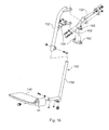
- Fig. 16 shows a second foot rest arrangement.
- cranked members 150 are provided with telescopic upper and lower parts 152, 154 to permit height adjustment of the foot rests 146.
- the cranked member 150 are pivotally mounted to mounting brackets 156 to permit the foot rests 146 to be pivoted out of the way when required.
- the mounting brackets 156 include cranked members 158 mountable to the brackets 142 and providing upper and lower pivotal mountings 160, 162 as well as a catch arrangement 164 for retaining the foot rests 146 in a use position.
- chassis frames may take a different form.
- a different arrangement could be provided to enable tilting of the respective frame parts.
- a different catch may be usable in the seat mounting arrangement.
- an arrangement with a hydraulic actuator could be used to vary the length of the first form of the interconnection arrangement.
- a different handle arrangement may be provided, and an arrangement which folds about a generally vertical central axis could be used.
Landscapes
- Health & Medical Sciences (AREA)
- Life Sciences & Earth Sciences (AREA)
- Animal Behavior & Ethology (AREA)
- General Health & Medical Sciences (AREA)
- Public Health (AREA)
- Veterinary Medicine (AREA)
- Carriages For Children, Sleds, And Other Hand-Operated Vehicles (AREA)
- Automatic Cycles, And Cycles In General (AREA)
- Seats For Vehicles (AREA)
Applications Claiming Priority (2)
| Application Number | Priority Date | Filing Date | Title |
|---|---|---|---|
| GBGB0509917.1A GB0509917D0 (en) | 2005-05-14 | 2005-05-14 | Wheelchairs |
| EP06252484.8A EP1721592B1 (fr) | 2005-05-14 | 2006-05-11 | Fauteuils roulants |
Related Parent Applications (1)
| Application Number | Title | Priority Date | Filing Date |
|---|---|---|---|
| EP06252484.8 Division | 2006-05-11 |
Publications (1)
| Publication Number | Publication Date |
|---|---|
| EP2263630A1 true EP2263630A1 (fr) | 2010-12-22 |
Family
ID=34708208
Family Applications (2)
| Application Number | Title | Priority Date | Filing Date |
|---|---|---|---|
| EP10011572A Withdrawn EP2263630A1 (fr) | 2005-05-14 | 2006-05-11 | Fauteuils roulants |
| EP06252484.8A Not-in-force EP1721592B1 (fr) | 2005-05-14 | 2006-05-11 | Fauteuils roulants |
Family Applications After (1)
| Application Number | Title | Priority Date | Filing Date |
|---|---|---|---|
| EP06252484.8A Not-in-force EP1721592B1 (fr) | 2005-05-14 | 2006-05-11 | Fauteuils roulants |
Country Status (2)
| Country | Link |
|---|---|
| EP (2) | EP2263630A1 (fr) |
| GB (1) | GB0509917D0 (fr) |
Families Citing this family (2)
| Publication number | Priority date | Publication date | Assignee | Title |
|---|---|---|---|---|
| ATE553737T1 (de) | 2007-12-21 | 2012-05-15 | Sunrise Medical Gmbh & Co Kg | Rollenscheibe, rollstuhlrahmen und rollstuhl |
| ATE496605T1 (de) | 2008-10-10 | 2011-02-15 | Sunrise Medical Gmbh & Co Kg | ROLLSTUHL MIT FUßSTÜTZE |
Citations (7)
| Publication number | Priority date | Publication date | Assignee | Title |
|---|---|---|---|---|
| US4555121A (en) * | 1984-09-20 | 1985-11-26 | Invacare Corporation | Invalid's chair to facilitate transfer to an automobile |
| US5718442A (en) * | 1995-12-27 | 1998-02-17 | Mechanical Application Designs, Inc. | Power wheelchair with extended power seat frame tilt |
| US5727802A (en) * | 1994-07-14 | 1998-03-17 | Everest & Jennings International Ltd. | Suspension wheelchair and wheelchair frame |
| WO1999017701A1 (fr) * | 1997-10-06 | 1999-04-15 | Pride Health Care, Inc. | Fauteuil roulant pliable commande par moteur |
| US6311999B1 (en) * | 1997-12-23 | 2001-11-06 | Kueschall Design Ag | Wheelchair with a closed three-dimensional frame |
| US20030006578A1 (en) * | 1998-10-01 | 2003-01-09 | Freedom Designs Incorporated | Size-adjustable laterally-folding tilting-frame wheelchair |
| EP1522293A2 (fr) * | 2003-10-08 | 2005-04-13 | Pride Mobility Products Corporation | Fauteuil roulant motorisé transportable |
-
2005
- 2005-05-14 GB GBGB0509917.1A patent/GB0509917D0/en not_active Ceased
-
2006
- 2006-05-11 EP EP10011572A patent/EP2263630A1/fr not_active Withdrawn
- 2006-05-11 EP EP06252484.8A patent/EP1721592B1/fr not_active Not-in-force
Patent Citations (7)
| Publication number | Priority date | Publication date | Assignee | Title |
|---|---|---|---|---|
| US4555121A (en) * | 1984-09-20 | 1985-11-26 | Invacare Corporation | Invalid's chair to facilitate transfer to an automobile |
| US5727802A (en) * | 1994-07-14 | 1998-03-17 | Everest & Jennings International Ltd. | Suspension wheelchair and wheelchair frame |
| US5718442A (en) * | 1995-12-27 | 1998-02-17 | Mechanical Application Designs, Inc. | Power wheelchair with extended power seat frame tilt |
| WO1999017701A1 (fr) * | 1997-10-06 | 1999-04-15 | Pride Health Care, Inc. | Fauteuil roulant pliable commande par moteur |
| US6311999B1 (en) * | 1997-12-23 | 2001-11-06 | Kueschall Design Ag | Wheelchair with a closed three-dimensional frame |
| US20030006578A1 (en) * | 1998-10-01 | 2003-01-09 | Freedom Designs Incorporated | Size-adjustable laterally-folding tilting-frame wheelchair |
| EP1522293A2 (fr) * | 2003-10-08 | 2005-04-13 | Pride Mobility Products Corporation | Fauteuil roulant motorisé transportable |
Also Published As
| Publication number | Publication date |
|---|---|
| EP1721592B1 (fr) | 2013-08-07 |
| EP1721592A3 (fr) | 2006-11-22 |
| EP1721592A2 (fr) | 2006-11-15 |
| GB0509917D0 (en) | 2005-06-22 |
Similar Documents
| Publication | Publication Date | Title |
|---|---|---|
| US8573622B2 (en) | Wheelchair | |
| CA2198643C (fr) | Fauteuil roulant pour personnes de grande taille | |
| US20030006578A1 (en) | Size-adjustable laterally-folding tilting-frame wheelchair | |
| GB2354211A (en) | A wheel chair | |
| US5560627A (en) | Low cost wheelchair | |
| US20060097478A1 (en) | Anti-tip wheelchair | |
| US20090146389A1 (en) | Wheelchair | |
| US4934722A (en) | Folding wheelchair | |
| NL1024201C2 (nl) | Rolstoel voorzien van beensteun met kuitsteun. | |
| AU2001281097A1 (en) | A wheelchair seat having adjustable telescoping assembly | |
| US6224156B1 (en) | Seat back recliner kit for wheelchair | |
| US7192042B2 (en) | Adjustable seating system | |
| US20070085301A1 (en) | Center-of-gravity tilt-in-space wheelchair | |
| US7222921B2 (en) | Wheelchair with foot rest | |
| EP1721592B1 (fr) | Fauteuils roulants | |
| EP1011596B1 (fr) | Deambulateur | |
| AU2007231838A1 (en) | Improved Rollator | |
| US8919808B2 (en) | Stroller, especially rehab stroller | |
| JPH0337063A (ja) | 車椅子用リクライニング背もたれ組立体 | |
| EP0945114A1 (fr) | Fauteuil roulant basculant avec élément de support à ressort | |
| JP4662761B2 (ja) | 車椅子用の折り畳み式転倒防止装置 | |
| US20060131833A1 (en) | Wheelchairs | |
| EP1230120A2 (fr) | Chaise roulante perfectionnee a siege inclinable | |
| CA2185258C (fr) | Repose-pieds extensible et relevable pour fauteuil roulant | |
| NZ328792A (en) | Foldable chair with back rest of variable inclination |
Legal Events
| Date | Code | Title | Description |
|---|---|---|---|
| PUAI | Public reference made under article 153(3) epc to a published international application that has entered the european phase |
Free format text: ORIGINAL CODE: 0009012 |
|
| AC | Divisional application: reference to earlier application |
Ref document number: 1721592 Country of ref document: EP Kind code of ref document: P |
|
| AK | Designated contracting states |
Kind code of ref document: A1 Designated state(s): AT BE BG CH CY CZ DE DK EE ES FI FR GB GR HU IE IS IT LI LT LU LV MC NL PL PT RO SE SI SK TR |
|
| STAA | Information on the status of an ep patent application or granted ep patent |
Free format text: STATUS: THE APPLICATION IS DEEMED TO BE WITHDRAWN |
|
| 18D | Application deemed to be withdrawn |
Effective date: 20110623 |