EP2263833B1 - Outil motorisé à limitation de couple n'utilisant qu'un moyen de détection de déplacement angulaire - Google Patents
Outil motorisé à limitation de couple n'utilisant qu'un moyen de détection de déplacement angulaire Download PDFInfo
- Publication number
- EP2263833B1 EP2263833B1 EP10176906A EP10176906A EP2263833B1 EP 2263833 B1 EP2263833 B1 EP 2263833B1 EP 10176906 A EP10176906 A EP 10176906A EP 10176906 A EP10176906 A EP 10176906A EP 2263833 B1 EP2263833 B1 EP 2263833B1
- Authority
- EP
- European Patent Office
- Prior art keywords
- output shaft
- rotational angle
- workpiece
- motor
- detecting
- Prior art date
- Legal status (The legal status is an assumption and is not a legal conclusion. Google has not performed a legal analysis and makes no representation as to the accuracy of the status listed.)
- Expired - Lifetime
Links
- 230000001186 cumulative effect Effects 0.000 claims description 24
- 230000008859 change Effects 0.000 claims description 16
- 238000000034 method Methods 0.000 description 86
- 230000008569 process Effects 0.000 description 84
- 238000001514 detection method Methods 0.000 description 41
- 230000007246 mechanism Effects 0.000 description 7
- 238000010586 diagram Methods 0.000 description 4
- 230000000630 rising effect Effects 0.000 description 4
- 230000009471 action Effects 0.000 description 2
- 229910000831 Steel Inorganic materials 0.000 description 1
- OJIJEKBXJYRIBZ-UHFFFAOYSA-N cadmium nickel Chemical compound [Ni].[Cd] OJIJEKBXJYRIBZ-UHFFFAOYSA-N 0.000 description 1
- 230000007423 decrease Effects 0.000 description 1
- 230000003116 impacting effect Effects 0.000 description 1
- JEIPFZHSYJVQDO-UHFFFAOYSA-N iron(III) oxide Inorganic materials O=[Fe]O[Fe]=O JEIPFZHSYJVQDO-UHFFFAOYSA-N 0.000 description 1
- 230000002045 lasting effect Effects 0.000 description 1
- 239000000463 material Substances 0.000 description 1
- 229910052751 metal Inorganic materials 0.000 description 1
- 239000002184 metal Substances 0.000 description 1
- 229910052987 metal hydride Inorganic materials 0.000 description 1
- 239000000203 mixture Substances 0.000 description 1
- 230000004048 modification Effects 0.000 description 1
- 238000012986 modification Methods 0.000 description 1
- 229910052759 nickel Inorganic materials 0.000 description 1
- PXHVJJICTQNCMI-UHFFFAOYSA-N nickel Substances [Ni] PXHVJJICTQNCMI-UHFFFAOYSA-N 0.000 description 1
- -1 nickel metal hydride Chemical class 0.000 description 1
- 230000002093 peripheral effect Effects 0.000 description 1
- 230000010363 phase shift Effects 0.000 description 1
- 239000010959 steel Substances 0.000 description 1
- 239000002023 wood Substances 0.000 description 1
Images


Classifications
-
- B—PERFORMING OPERATIONS; TRANSPORTING
- B25—HAND TOOLS; PORTABLE POWER-DRIVEN TOOLS; MANIPULATORS
- B25B—TOOLS OR BENCH DEVICES NOT OTHERWISE PROVIDED FOR, FOR FASTENING, CONNECTING, DISENGAGING OR HOLDING
- B25B21/00—Portable power-driven screw or nut setting or loosening tools; Attachments for drilling apparatus serving the same purpose
- B25B21/02—Portable power-driven screw or nut setting or loosening tools; Attachments for drilling apparatus serving the same purpose with means for imparting impact to screwdriver blade or nut socket
-
- B—PERFORMING OPERATIONS; TRANSPORTING
- B25—HAND TOOLS; PORTABLE POWER-DRIVEN TOOLS; MANIPULATORS
- B25B—TOOLS OR BENCH DEVICES NOT OTHERWISE PROVIDED FOR, FOR FASTENING, CONNECTING, DISENGAGING OR HOLDING
- B25B23/00—Details of, or accessories for, spanners, wrenches, screwdrivers
- B25B23/14—Arrangement of torque limiters or torque indicators in wrenches or screwdrivers
- B25B23/145—Arrangement of torque limiters or torque indicators in wrenches or screwdrivers specially adapted for fluid operated wrenches or screwdrivers
- B25B23/1453—Arrangement of torque limiters or torque indicators in wrenches or screwdrivers specially adapted for fluid operated wrenches or screwdrivers for impact wrenches or screwdrivers
-
- B—PERFORMING OPERATIONS; TRANSPORTING
- B25—HAND TOOLS; PORTABLE POWER-DRIVEN TOOLS; MANIPULATORS
- B25B—TOOLS OR BENCH DEVICES NOT OTHERWISE PROVIDED FOR, FOR FASTENING, CONNECTING, DISENGAGING OR HOLDING
- B25B23/00—Details of, or accessories for, spanners, wrenches, screwdrivers
- B25B23/14—Arrangement of torque limiters or torque indicators in wrenches or screwdrivers
- B25B23/147—Arrangement of torque limiters or torque indicators in wrenches or screwdrivers specially adapted for electrically operated wrenches or screwdrivers
- B25B23/1475—Arrangement of torque limiters or torque indicators in wrenches or screwdrivers specially adapted for electrically operated wrenches or screwdrivers for impact wrenches or screwdrivers
Definitions
- the present invention relates to power tools and more particularly, relates to power tools, such as impact wrenches and impact screwdrivers.
- EP 1 208 946 relates to a method of controlling tools providing a torque to a screw member sude as bolt and rust and to a power tooll according to the preamble of independent claim 1.
- Japanese Laid-open Patent Publication No. 6-304879 describes an impact wrench that can be used firmly tighten fasteners, such as a bolt or nut.
- This known impact wrench has an output shaft (drive shaft) and a hammer that strikes the output shaft.
- a socket is attached to a distal end of the output shaft.
- a fastener may be disposed within the socket.
- the output shaft is forcibly rotated in order to tighten the fastener within or to a workpiece.
- the hammer is allowed to slip and freely rotate with respect to the output shaft when a predetermined amount of torque is exerted.
- the hammer when a load for rotating the output shaft is light (i.e., before the fastener becomes seated against the workpiece), the hammer continuously rotates the output shaft in order to continuously tighten the fastener.
- the head of the fastener has contacted the workpiece (i.e., after the fastener has become seated against the workpiece)
- the hammer will begin to slip and rotate freely. Therefore, the hammer will impact the output shaft after rotating by predetermined angle. By repetition of the slipping and impacting action, the output shaft will rotate a small amount each time the hammer impacts the output shaft and the fastener can be tightened to an appropriate torque.
- This known impact wrench further includes an impact detecting sensor that detects whether the hammer is distant from the output shaft (i.e., whether the hammer slips with respect to the output shaft), and a rotational angle detecting sensor that measures the rotational angle of the output shaft.
- the impact detecting sensor outputs an OFF signal when the hammer is in an engaged state with the output shaft, and outputs an ON signal when the hammer is distant from the output shaft.
- the rotational angle detecting sensor outputs a signal that corresponds to the rotational angle of the output shaft.
- a controller of the impact wrench detects changes in the rotational angle of the output shaft in the period between the impact detecting sensor outputting one ON signal and outputting a subsequent ON signal, and determines from the changes in the rotational angle of the output shaft whether the tightening torque of the fastener has reached a predetermined value (i.e., whether the fastener has become seated against the workpiece).
- a predetermined value i.e., whether the fastener has become seated against the workpiece.
- the known impact wrench must have not only the rotational angle detecting sensor for measuring the rotational angle of the output shaft, but also the impact detecting sensor for detecting that the hammer has struck the output shaft. That is, a small amount of play usually exists between the socket and the fastener. Therefore, when the output shaft tightens the fastener, a cycle (repetition) of normal rotation (rotation in a tightening direction) and reverse rotation (rotation in a loosening direction) is typically repeated due to a reaction (hammering action) that is produced when the impact force of the output shaft is transmitted to the fastener. Consequently, the socket (i.e., output shaft) of the impact wrench may continue repeat the cycle of normal rotation and reverse rotation due to the hammering action. In the known impact wrench, this continual rotation means that the rotational angle detecting sensor alone cannot reliably detect at which time the hammer struck the output shaft. As a result, the known impact wrench must include the impact detecting sensor.
- power tools may include a motor, such as an electric or pneumatic motor, and an oil pulse unit that generates an elevated torque (i.e., oil pulse).
- the oil pulse unit may be coupled to the motor and have an output shaft. When a load acting on the output shaft is less than a predetermined value, rotating torque generated by the motor is directly transmitted to the output shaft. When the load acting on the output shaft exceeds the predetermined value, an elevated torque is generated by the oil pulse unit and applied to the output shaft.
- the output shaft may be connected to a load shaft.
- a socket for engaging fasteners e.g., bolt, nut or screw
- the load shaft is preferably rotated in order to tighten the fastener within or to a workpiece.
- Such power tools may also include a detecting device for detecting change in rotational angle of the output shaft (or the load shaft) and the direction of rotation thereof, such as a rotary encoder, and a control device, such as a processor, microprocessor or microcomputer.
- the detecting device may output signals corresponding to a state of the output shaft (or the load shaft) to the control device.
- the control device may store the state of the output shaft (or the load shaft) within a memory at predetermined interval.
- the control device may further determine a generating time, at which the oil pulse unit generates the elevated torque, based upon the state of the output shaft (or the load shaft). For example, when change in the rotational angle of the output shaft (or the load shaft) has occurred, the control device first calculates the changes in the rotational angle of the output shaft (or the load shaft) in the tightening direction during a first predetermined period extending from a time prior to the change in the rotational angle until the change in the rotational angle occurs. When the calculated changes in the rotational angle are within a first predetermined value, it can be determined that the output shaft (the load shaft) has substantially stopped rotating.
- the control device when the calculated changes in the rotational angle are within a first predetermined value (i.e., the output shaft (the load shaft) has substantially stopped rotating), the control device further calculates the absolute value of the changes in the rotational angle of the output shaft (the load shaft) in a period lasting from the change in the rotational angle until a second predetermined period has elapsed. If the absolute value of the changes in the rotational angle is greater than a second predetermined value, the control device determines that the time at which the change in the rotational angle was occurred corresponds to a time at which an oil pulse was generated by the oil pulse unit.
- the control device determines that the time at which the change in the rotational angle was occurred was not a time at which an oil pulse was generated by the oil pulse unit.
- the control device can determine, using only the signals from the detecting device, whether the current state is one where the oil pulse was applied to the output shaft.
- the changes in the rotational angle of the output shaft (the load shaft) in the tightening direction per one oil pulse differs greatly depending on whether this occurs before or after seating the fastener. That is, there are large changes in the rotational angle of the output shaft (load shaft) before the fastener is seated, and small changes in the rotational angle of the output shaft (load shaft) after the fastener is seated. As a result, it is possible to determine whether the fastener has been seated by determining the extent by which the rotational angle of the output shaft changes per one oil pulse.
- the control device may further determine whether the fastener has reached the seated position against the workpiece based upon the state of the output shaft (the load shaft). For example, the control device may calculates the changes in the rotational angle of the output shaft (the load shaft) in the tightening direction from the time, at which an oil pulse was generated by the oil pulse unit, until a predetermined period has elapsed. Then, the control device may determine whether the fastener has reached a seated position against the workpiece based upon the calculated changes in the rotational angle. Specifically, when the calculated changes in the rotational angle is within the third predetermined value, the control device may determine that the fastener has reached a seated position against the workpiece. Preferably, the control device may stop the motor when a predetermined time has elapsed after determining that the fastener has reached the seated position against the workpiece. Therefore, the fastener can be adequately and appropriately tightened.
- power tools may include a hammer that is adapted to strike an anvil to thereby rotate the anvil and generate the elevated torque. If the hammer and the anvil are utilize to generate elevated torque, instead of an oil pulse, the control device is preferably programmed to count the number of impact of the hammer striking the anvil after the fastener has reached the seated position against the workpiece. For example, when the number of impacts reaches a predetermined or preset number, the motor is automatically stopped.
- power tools are taught that are capable of tightening fasteners using a sufficient or adequate tightening torque, even if fasteners are tightened within or to several type of workpieces.
- the tightening torque of the fastener changes if the type of workpiece (e.g., the material (hardness) of workpiece) differs.
- the appropriate tightening torque of the fastener is determined by the type of fastener and not by the type of workpiece, such that if the fasteners are same, the appropriate tightening torque values are same.
- the auto stop conditions must be changed to correspond to the type of workpiece.
- the power tools may have automatic stop programs for automatically stopping the motor for each of differing types of workpiccc.
- the control device may determine the type of workpiece based upon the signals from the detecting device. For example, the control device may (1) calculate a cumulative rotational angle of the output shaft (the load shaft) in the tightening direction within a predetermined period after the fastener has reached the seated position against the workpiece, and (2) determine the type of workpiece based upon the calculated cumulative rotational angle.
- control device may (1) calculate average changes in rotational angle of the output shaft (the load shaft) in the tightening direction per one elevated torque after the fastener has reached the seated position against the workpiece, and (2) determine the type of workpiece based upon the calculated average changes.
- control device may select the automatic stop program based upon the determined type of workpiece, and stop the motor in accordance with the selected automatic stop program.
- the control device automatically chooses the automatic stop programs that correspond to the type of workpiece, the fastener can be tightened with the appropriate tightening torque.
- FIG. 1 shows a first representative embodiment of the present teachings, which is right-angle soft impact wrench 11 having a motor (not shown in Fig. 1 , but shown as motor M in Fig. 6 ) that is disposed within housing 13.
- Planetary gear mechanism 28 is connected to output shaft 30, which is coupled to motor M.
- Oil pulse unit 22 is connected to output shaft 26 of planetary gear mechanism 28 via cushioning mechanism 24.
- Oil pulse unit 22 is a known device that causes output shaft 18 to instantaneously produce a large impact force (oil pulse) by using the pressure of the oil that is disposed within oil pulse unit 22.
- the impact force can be controlled by adjusting the maximum pressure of the oil disposed within oil pulse unit 22.
- a predetermined tightening torque can be produced.
- Cushioning mechanism 24 may be, e.g., a known mechanism (e.g., described in Japanese Unexamined Utility Model No. 7-31281 ) for preventing the impact force, which is produced by the oil pulse, from being directly transmitted to planetary gear mechanism 28.
- Output shaft 18 of oil pulse unit 22 is rotatably supported by bearing device 20, and bevel gear 16 is disposed on a distal end of output shaft 18.
- Bevel gear 16 engages another bevel gear 14, which is disposed on one end of spindle 12.
- Spindle 12 is rotatably supported perpendicular to output shaft 18 (i.e., thereby defining a "right-angle" impact wrench).
- a socket (not shown) may be utilized to engage the head of a fastener and may be fixedly or removably attached to the other end of spindle 12.
- oil pulse unit 22 When motor M rotates, the output rotational speed of motor M is reduced by planetary gear mechanism 28 and the reduced output rotational speed is transmitted to oil pulse unit 22.
- the lead on spindle 12 (output shaft 18) is low at the initial stage of tightening. Therefore, the rotational energy generated by motor M is directly transmitted to spindle 12 without generating an oil pulse. As a result, spindle 12 will continuously rotate, thereby continuously tightening the fastener.
- the load on spindle 12 (output shaft 18) will increase. At that time, oil pulse unit 22 will generate oil pulses in order to produce an elevated torque and more firmly tighten the fastener using the impact force generated by the oil pulses.
- bearing device 20 rotatably supports output shaft 18 of oil pulse unit 22, which is actuated in the above-described manner.
- Fig. 2 is a cross-sectional view showing a representative structure for bearing device 20.
- bearing device 20 may include outer cylinder 44, which freely and rotatably supports inner cylinder 40.
- a through-hole may be defined within inner cylinder 40.
- the diameter of the through-hole is preferably substantially the same as outside diameter of output shaft 18 of oil pulse unit 22 (i.e., slightly smaller than the outside diameter of output shaft 18).
- Output shaft 18 of oil pulse unit 22 is firmly inserted into the through-hole from the right side, as viewed in Fig. 2 .
- inner cylinder 40 is affixed onto output shaft 18. Accordingly, when output shaft 18 rotates, inner cylinder 40 integrally rotates with output shaft 18.
- Magnet mounting member 50 may have a cylindrical shape and may be affixed onto the right side of inner cylinder 40, as shown in Fig. 2 .
- a plurality of permanent magnets 52 i.e., indicated by reference numerals 52a, 52b, 52c in Fig. 3
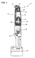
- Fig. 3 schematically shows a representative positional relationship between magnets 52, which are disposed within the bearing device 20, and rotational angle detecting sensors, 48a and 48b.
- magnets 52 may be divided into two groups. One group consists of magnets 52a, 52c, etc., which are disposed such that their respective South poles face outward. The other group consists of magnet(s) 52b, etc., which are disposed such that their respective North poles face outward. That is, the South poles and the North poles are alternately disposed outward.
- the angle ⁇ is defined between adjacent magnet. In other words, the angle ⁇ is defined by a line connecting the center of magnet 52a and the rotational center of inner cylinder 40 and a line connecting the center of magnet 52b and the rotational center of inner cylinder 40, as shown in Fig. 3 .
- outer cylinder 44 is a cylindrical member having an inner diameter that is greater than the outer diameter of inner cylinder 40.
- a plurality of bearing balls 42 is disposed between inner cylinder 40 and outer cylinder 44 in order to rotatably support inner cylinder 40 relative to outer cylinder 44. Therefore, when outer cylinder 44 is accommodated and affixed within housing 13, inner cylinder 40 (i.e., output shaft 18) is rotatably supported relative to outer cylinder 44 (i.e., housing 13).
- Sensor mounting member 46 may have a cylindrical shape and may be affixed to the right side of outer cylinder 44, as viewed in Fig. 2 .
- Rotational angle detecting sensors 48a, 48b may be disposed on the internal wall of sensor mounting member 46.
- sensors 48a, 48b are disposed so as to face magnets 52 (see Fig. 3 ).
- Each rotational angle detecting sensor 48a, 48b may be a latch type Hall IC, which detects changes in magnetic fields. According to the detected changes of the magnetic field, each sensor 48a, 48b switches the state (e.g., voltage level) of a detection signal that is outputted, e.g., to microcomputer 60 (see Fig. 6 ).
- rotational angle detecting sensors 48a, 48b may each include a Hall element, which serves as a magnetic sensor, and an IC, which converts output signals from the Hall element into digital signals. For example, when a North-pole magnetic field is applied to each sensor 48a, 48b, the signal output from the sensor may be switched to a HIGH level. When a South-pole magnetic field is applied to each sensor 48a, 48b, the signal output from the sensor may be switched to a LOW level.
- Rotational angle detecting sensors 48a, 48b may be displaced from each other by angle ⁇ , as shown in Fig. 3 .
- inner cylinder 40 i.e., output shaft 18
- the detection signals that are respectively output from rotational angle detecting sensors 48a, 48b change as shown in Fig. 4.
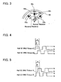
- Fig. 4 shows the timings of the outputs of detection signals that are supplied from two corresponding rotational angle-detecting sensors 48a, 48b when output shaft 18 rotates normally (i.e., in the forward direction).
- the detection signals that are output from rotational angle detection sensors 48a, 48b are switched to the LOW level when magnets 52a, 52c, etc., whose South-poles are disposed outward, face or directly oppose sensors 48a, 48b, and to the HIGH level when magnet(s) 52b, etc., whose North-poles are disposed outward, face or directly oppose sensors 48a, 48b.
- rotational angle detecting sensors 48a, 48b and magnets 52a, 52b, and 52c may be positioned, e.g., as shown in Fig. 3 , and output shaft 18 may be rotated in the normal (forward or tightening) direction. Because, in Fig. 3 , rotational angle detecting sensor 48a faces magnet 52b (i.e., its North pole is disposed outward), the detection signal of sensor 48a is at a HIGH level.
- the detection signal of rotational angle detecting sensor 48b is at a LOW level because magnet 52c (i.e., its South pole is disposed outward) has passed detecting sensor 48b.
- magnet 52c i.e., its South pole is disposed outward
- magnet 52b i.e., its North pole is disposed outward
- the detection signal of sensor 48b will be switched from the LOW level to the HIGH level.
- the detection signal of sensor 48a When inner cylinder 40 further rotates by angle ( ⁇ - ⁇ ), magnet 52a will face rotational angle detecting sensor 48a. Therefore, the detection signal of sensor 48a will be switched from the HIGH level to the LOW level. In the same manner as was describe more fully above, the detection signal of sensor 48b is switched when output shaft 18 rotates (in the normal direction) by angle ⁇ after the detection signal level of sensor 48a is switched.
- FIG. 5 shows the timings of the outputs of detection signals that are supplied from two corresponding rotational angle-detecting sensors 48a, 48b when output shaft 18 rotates in the reverse direction.
- the detection signal of rotational angle detecting sensor 48a switches when output shaft 18 rotates (in the reverse direction) by angle ⁇ after the detection signal level of sensor 48b switches.
- each of rotational angle detecting sensor 48a, 48b is switched each time inner cylinder 40 (i.e., output shaft 18 of oil pulse unit 22) rotates by angle ⁇ . Accordingly, each sensor 48a, 48b outputs one pulse each time output shaft 18 rotates by the angle (2 ⁇ ). The rising edge and falling edge of each pulse may be detected by microcomputer 60 in order to detect changes in the rotational angle of output shaft 18.
- the rising edge of the detection signal from rotational angle detecting sensor 48a is detected at the time t1.
- the direction of rotation of output shaft 18 is determined based on whether the pulse edge detected immediately prior to this pulse edge occurred in the rotational angle detecting sensor 48a or 48b.
- the pulse edge detected immediately prior to this pulse edge was a falling edge of rotational angle detecting sensor 48b. Therefore, it can be determined that output shaft 18 is rotating in the direction of normal rotation, and the rotational angle of output shaft 18 increases by ⁇ / 2.
- the rising edge of the detection signal of rotational angle detecting sensor 48b is detected at the time t5. Since, relative to the time t4, the falling edge of the detection signal of rotational angle detection sensor 48b was detected, it can be determined that the direction of rotation of output shaft 18 has changed (i.e., it can be determined that output shaft 18 has rotated in the direction of reverse rotation). As a result, the rotational angle of output shaft 18 decreases by ⁇ / 2. Similarly, it is determined at time t6 that the direction of rotation of output shaft 18 has changed and is in the direction of normal rotation, and it can be detected at times t7 to t10 that output shaft 18 is rotating in the direction of normal rotation.
- soft impact wrench 11 may include main switch 32 for starting and stopping motor M as shown in FIG. 1 .
- detachable battery pack 34 may be removably attached to a lower end of housing 13. Battery pack 34 may supply current to motor M, microcomputer 60, etc.
- a representative control circuit for use with soft impact wrench 11 will now be described with reference to Fig. 6 .
- the representative control circuit of soft impact wrench 11 utilizes microcomputer 60 as the main component.
- Microcomputer 60 is preferably disposed within housing 13.
- Microcomputer 60 may be an integrated circuit containing CPU 62, ROM 64, RAM 66 and I/O 68, and may be connected as shown in Fig. 6 .
- ROM 64 may store a control program for automatically stopping motor M, and other programs.
- Rotational angle detecting sensors 48a, 48b are respectively connected to predetermined input ports of I/O 68. Thus, detection signals output from each of sensors 48, 48b can be input to microcomputer 60.
- Battery pack 34 is connected to microcomputer 60 via power source circuit 74.
- Battery pack 34 may include a plurality of rechargeable battery cells (e.g., nickel metal hydride battery cells, nickel cadmium battery cells) that are serially connected.
- battery pack 34 is preferably connected to motor M via drive circuit 72.
- Motor M is connected to microcomputer 60 via drive circuit 72 and brake circuit 70.
- microcomputer 60 may execute a program based upon the input detection signals, stop the supply of power to motor M at a given timing, and actuate brake circuit 70 in order to stop motor M.
- FIG. 8 shows a representative memory structure for RAM 66 of microcomputer 60.
- the pulse edge information detected by rotational angle detecting sensors 48a, 48b may be stored within storage registers R1 ⁇ R10 of RAM 66.
- microcomputer 60 may detect the pulse edge from the rotational angle detecting sensors 48a, 48b and stores the pulse edge that have been detected, and the direction of rotation, in the storage registers R1 ⁇ R10. Specifically, '01' is stored when a pulse edge in the direction of normal rotation has been detected, 'FF' is stored when a pulse edge in the direction of reverse rotation has been detected, and '00' is stored when no pulse edge has been detected.
- output shaft 18 has rotated only one portion (i.e., ⁇ / 2) in the direction of normal rotation during the period in which the pulse edges are stored in the storage registers R1 ⁇ R10.
- microcomputer 60 Since the intervals at which microcomputer 60 detects the pulse edges are sufficiently short (e.g., 0.2 milliseconds), no more than two pulse edges occur during one detecting time interval. Further, microcomputer 60 may be programmed to store the pulse edge information in order from register R1 to R10. Thus, microcomputer 60 may be programmed such that, when pulse edge information have been stored in the entirety of the storage registers R1 ⁇ R10, the information in registers R2 ⁇ R10 is shifted to registers R1 ⁇ R9, and new pulse edge information is stored in register R10. By this means, the oldest stored pulse edge information is cleared first.
- a representative method for utilizing microcomputer 60 in order to tighten a fastener using soft impact wrench 11 will be explained with reference to the representative flowcharts of Figs. 9-13 .
- the operator may first insert the fastener into the socket attached to the distal end of spindle 12 and then turn ON main (trigger) switch 32.
- main switch 32 is turned ON (actuated)
- microcomputer 60 starts the drive of motor M and also executes the representative control program, which will be discussed below.
- microcomputer 60 when main switch 32 has been turned ON, microcomputer 60 first resets: the storage registers R1 ⁇ R10, a seating detecting counter C, and an auto stop timer, and then activates the motor M (step S10).
- the seating detecting counter C is a counter that counts the number of times it has been determined that the fastener is seated against the workpiece.
- the auto stop timer is a timer that determines whether to stop motor M.
- microcomputer 60 resets a seating detecting timer T and starts the seating detecting timer T (step S12).
- the seating detecting timer T is a timer required when a seating detecting process (i.e., steps S14 ⁇ S34) is performed.
- microcomputer 60 starts a first pulse edge detecting process (step S14).
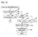
- the first pulse edge detecting process will be described with reference to FIG. 10 .
- microcomputer 60 determines whether a pulse edge has occurred in the detection signals from rotational angle detecting sensors 48a, 48b (step S38). If a pulse edge has not occurred (NO in step S38), '00' is stored in the storage register R (step S40), the process returns to step S12 of FIG. 9 .
- microcomputer 60 determines whether the pulse edge is in the direction of normal rotation or in the direction of reverse rotation (step S42).
- step S42 determines whether the pulse edge is in the direction of normal rotation or in the direction of reverse rotation.
- step S42 determines whether the pulse edge is in the direction of normal rotation or in the direction of reverse rotation.
- step S42 determines whether the pulse edge is in the direction of normal rotation (YES in step S42).
- '01' is stored in the storage register R (steps S44 and S48)
- 'FF' is stored in the storage register R (steps S46 and S48).
- microcomputer 60 calculates the changes in the rotational angle of output shaft 18 in the direction of normal rotation (i.e., the tightening direction) during T1 (millisecond) prior to the occurrence of the pulse edge (step S50).
- the pulse edges stored in the storage registers R1 ⁇ R10 are added together.
- microcomputer 60 determines whether the changes in the rotational angle calculated in step S50 of FIG. 10 is equal to or less than a "predetermined value 1" (e.g., ⁇ ). In the case where the changes in the rotational angle calculated in step S50 exceeds the "predetermined value 1" (NO in step S16), microcomputer 60 determines that output shaft 18 has been rotating during T1, the process returns to step S12. On the other hand, in the case where the changes in the rotational angle calculated in step S50 is equal to or less than the "predetermined value 1" (YES in step S16), microcomputer 60 determines that output shaft 18 has not been rotating during T1, and the process proceeds to step S18.
- a "predetermined value 1" e.g., ⁇
- a value of variable r is set to zero.
- the variable r is a variable for calculating the absolute value of the changes in the rotational angle of output shaft 18 occurring during T2 (millisecond) from the time when the pulse edge occurred.
- a value of variable R is set to the pulse edge detected in the first pulse edge detecting process (i.e., pulse edge information of step S44 or step S46 in FIG. 10 ).
- the variable R is a variable for calculating the changes in the rotational angle in the direction of normal rotation of output shaft 18 occurring during T3 (millisecond) from the time when the pulse edge has occurred.
- step S24 microcomputer 60 determines whether the seating detecting timer T has reached T2 (millisecond). If the seating detecting timer T has reached T2 (millisecond) (YES in step S24), the process proceeds to step S28. On the other hand, if the seating detecting timer T has not reached T2 (millisecond) (NO in step S24), the process proceeds to step S26.
- microcomputer 60 starts a second pulse edge detecting process.
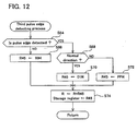
- the second pulse edge detecting process will be explained with reference to FIG. 11 .
- microcomputer 60 determines whether a pulse edge has occurred in the detecting signals of rotational angle detecting sensors 48a, 48b (step S52). In the case where a pulse edge has not occurred (NO in step S52), '00' is stored in registers R45 and r45, and the process proceeds to step S62. On the other hand, in the case where a pulse edge has occurred (YES in step S52), microcomputer 60 determines whether the pulse edge is in the direction of normal rotation or in the direction of reverse rotation (step S56).
- step S56 When the pulse edge is in the direction of normal rotation (YES in step S56), '01' is stored in the registers R45, r45 (step S58). When the pulse edge is in the direction of reverse rotation (NO in step S56), 'FF' is stored in the register R45, and '01' is stored in the register r45 (step S60).
- step S62 the value of the register R45 is added to the variable R, and the value of the register r45 is added to the variable r.
- the changes in the rotational angle of output shaft 18 that has been detected is added to the variable R, and the absolute value of the changes in the rotational angle of output shaft 18 that has been detected is added to the variable r.
- the value of the register R45 is also stored in the storage register.
- microcomputer 60 determines whether the variable r (i.e., the absolute value of the changes in the rotational angle of output shaft 18) is equal to or greater than a "predetermined value 2" (e.g., ⁇ ) (step S28). That is, it is determined whether output shaft 18 has rotated since the detection of the pulse edge in the first pulse edge detecting process at step S14.
- a "predetermined value 2" e.g., ⁇
- step S28 determines that the time at which the pulse edge detected in the first pulse edge detecting process occurred is not the same as the time at which the generation of the oil pulse started (i.e., when oil pulse unit 22 generated the oil pulse, the pulse edge detected in the first pulse edge detecting process did not simultaneously occur), and the process returns to step S12.
- step S28 is determined to be YES
- microcomputer 60 determines that the time at which the pulse edge detected in the first pulse edge detecting process occurred is the same as the time at which the generation of the oil pulse started (i.e., when oil pulse unit 22 generated the oil pulse, the pulse edge detected in the first pulse edge detecting process simultaneously occurred), and the process proceeds to step S34.
- step S34 microcomputer 60 determines whether the seating detecting timer T has reached T3 (millisecond). When the seating detecting timer T has reached T3 (millisecond) (YES in step S34), the process proceeds to step S36 in which a motor stopping process is performed. When the seating detecting timer T has not reached T3 (millisecond) (NO in step S34), the process proceeds to step S32, in which a third pulse edge detecting process is performed.
- step S64 determines whether a pulse edge has occurred in the detecting signals from rotational angle detecting sensors 48a, 48b (step S64). If a pulse edge has not occurred (NO in step S64), '00' is stored in the register R45, and the process proceeds to step S74. On the other hand, if a pulse edge has occurred (YES in step S64), it is determined whether the pulse edge is in the direction of normal rotation or in the direction of reverse rotation (step S68). In the case where the pulse edge is in the direction of normal rotation (YES in step S68), '01' is stored in the register R45 (step S70). In the case where the pulse edge is in the direction of reverse rotation (NO in step S68), 'FF' is stored in the register R45 (step S72).
- step S74 the value of the register R45 is added to the variable R.
- the change in the rotational angle of the output shaft 18 that is detected every detecting time interval e.g., 0.2 milliseconds
- step S74 the value of the register R45 is stored in the storage registers.
- steps S34 and S32 are repeated until the seating detecting timer T reaches T3 (millisecond) (i.e., until the third pulse edge detecting process is performed ((T3 - T2) / (detecting time interval)) times).
- step S36 the motor stopping process of step S36 will be explained with reference to FIG. 13 .
- microcomputer 60 determines whether the value of the variable R (i.e., the changes in the rotational angle of output shaft 18 in the direction of normal rotation during the period from detecting the pulse edge in the first pulse edge detecting process until T3 (millisecond) has elapsed) is equal to or less than a "predetermined value 3" (step S76).
- the "predetermined value 3" may equally well be assigned a value appropriate to the type of fastener (e.g., screw, bolt or nut) or to the type of tightening operation.
- step S76 When the variable R exceeds the "predetermined value 3" (NO in step S76), it is determined that the fastener has not been seated against the workpiece, and the process proceeds to step S84. On the other hand, when the variable R is within the "predetermined value 3" (YES in step S76), it is determined that the fastener has been seated against the workpiece, and the process proceeds to step S78. That is, in the first representative embodiment, the seating of the fastener is determined by utilizing the fact that, when one oil pulse (i.e., impulse force) causes output shaft 18 to rotate in the direction of normal rotation, there is a lesser changes in the rotational angle after the fastener is seated than before the fastener is seated.
- one oil pulse i.e., impulse force
- step S76 When step S76 is YES, '1' is added to the seating detecting counter C (step S78), and it is determined whether the seating detecting counter C has reached '2' (step S80). If the seating detecting counter C has not reached '2' (NO in step S80), the process proceeds to step S84 so that a second seating detection is performed. If the seating detecting counter C has reached '2' (YES in step S80), microcomputer 60 starts the auto stop timer (step S86), and microcomputer 60 determines whether the auto stop timer is equal to a predetermined period T4 (millisecond) (step S88).
- T4 millisecond
- step S88 If the auto stop timer is not equal to the predetermined period T4 (millisecond) (NO in step S88), the process waits until the auto stop timer is equal to the predetermined period T4 (millisecond). Conversely, if the auto stop timer is equal to the predetermined period T4 (millisecond) (YES in step S88), microcomputer 60 stops the motor M (step S90).
- step S84 microcomputer 60 determines whether the seating detecting timer T is equal to a predetermined period T5 (millisecond) (step S84). In the case where the seating detecting timer T is not equal to the predetermined period T5 (millisecond) (NO in step S84), the process waits until the seating detecting timer T is equal to the predetermined period T5 (millisecond). In the case where the seating detecting timer T is equal to the predetermined period T5 (millisecond) (YES in step S84), the process returns to step S12 of FIG. 9 . Therefore, when seating detection is performed, the next seating detection is not performed until after T5 (millisecond) has elapsed. As a result, since the next seating detection is not affected by contact occurring when seating the fastener, the seating of the fastener can be accurately detected.
- the pulse edges of rotational angle detecting sensors 48a, 48b and the direction of rotation are detected and stored at specified time intervals in the storage registers R1 ⁇ R10, whereby the moving state (i.e., halted or rotating) of output shaft 18 prior to the detection of the pulse edge is determined. Furthermore, when it is determined that output shaft 18 is halted, further determining the moving state (halted or rotating) of output shaft 18 after the detection of the pulse edge renders it possible to determine whether the time at which the pulse edge occurred was the time at which an oil pulse was generated.
- the rotational angle detecting sensors 48a, 48b that detect the changes in rotational angle of output shaft 18 also specify the oil pulse generation time, thereby eliminating the need for the impact detecting sensor that is conventionally required.
- the second representative embodiment of the present teachings will now be explained. Before proceeding with a discussion of the second representative embodiment, some additional background information is in order.
- the tightening torque of the fastener changes if the type of workpiece (e.g., the hardness of workpiece) differs.
- the appropriate tightening torque of the fastener is determined by the type of fastener and not by the type of workpiece, such that if the fasteners are same, the appropriate tightening torque values are same.
- an impact wrench of the second representative embodiment is capable of automatically changing the motor auto stop conditions in accordance with the type of workpiece.
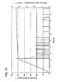
- FIG. 15 shows both changes in a cumulative rotational angle of the output shaft when a screw is tightened to a hard member such as steel (hereafter referred to as hard joint member), as well as changes in rotational angle of the output shaft per 1 impulse force after seating.
- FIG. 16 shows both changes in the cumulative rotational angle of the output shaft when a screw is tightened to a soft member such as wood (hereafter referred to as soft joint member), as well as changes in rotational angle of the output shaft per 1 impulse force after seating.
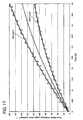
- FIG. 17 shows the change in the cumulative rotational angle of the output shaft after seating for the cases of the hard joint member and the soft joint member.
- the changes in the cumulative rotational angle of the output shaft are approximately identical prior to seating for both cases.
- the changes in the cumulative rotational angle of the output shaft differ greatly after seating.
- the hard joint member there are small changes in the rotational angle of the output shaft per 1 impulse, the screw hardly rotating after seating.
- the soft joint member there are large changes in the rotational angle of the output shaft per 1 impulse, and the screw rotates even after seating.
- the motor can be stopped using the hard joint member auto stop conditions if the workpiece is a hard joint member, and can be stopped using the soft joint member auto stop conditions if the workpiece is a soft joint member.
- the microprocessor can be programmed to: firstly (1) calculate, from the changes in the rotational angle of the output shaft and the direction of rotation thereof detected by the rotational angle detecting sensors, the cumulative rotational angle of the output shaft in the tightening direction occurring within a specified period, (2) determine the type of workpiece on the basis of the calculated cumulative rotational angle, and (3) stop the motor when the automatic stopping conditions corresponding to the type of workpiece that was identified have been fulfilled.
- the type of workpiece e.g., hard joint member or soft joint member
- the second representative embodiment provides an impact wrench for two types of workpieces (i.e., hard joint members (e.g., metal plates) and soft joint members (e.g., wooden boards).
- hard joint member motor auto stop conditions wherein a motor driving period after seating is T s1
- soft joint member motor auto stop conditions wherein a motor driving period after seating is T s2 . (Here, T s2 > T s1 )) are stored in ROM 64 of microcomputer 60.
- microcomputer 60 determines whether the workpiece to which the fastener is to be tightened is a hard joint member or a soft joint member, this driving motor M for the motor driving period T s1 after seating in the case where the workpiece is a hard joint member, and driving motor M for the motor driving period T s2 after seating in the case where the workpiece is a soft joint member.
- control circuit may be generally the same as the soft impact wrench of the first representative embodiment. Therefore, the same reference numerals will be used and the explanation of the same or similar parts may be omitted.
- microcomputer 60 performs the processes shown in the flowchart of FIG. 9 . Further, the first pulse edge detecting process ( FIG. 10 ), the second pulse edge detecting process ( FIG. 11 ), and the third pulse edge detecting process ( FIG. 12 ) are performed in a manner identical to the first representative embodiment. However, in the second representative embodiment, the motor stopping process shown at step S36 in FIG. 9 differs from the motor stopping process of the first embodiment. Below, the motor stopping process of the second representative embodiment will be explained with reference to the flowchart of FIG. 14 .
- step S92 determines whether a seating detecting flag F has reached '1' (step S92).
- the seating detecting flag F is a flag for showing whether the fastener is seated, this being '1' when the fastener is seated, and '0' when the fastener is not seated.
- step S92 since the seating detecting flag F is cleared in the initializing processes of step S10 in FIG. 9 , step S92 must be NO in the first performance of the motor stopping process after motor M has been activated.
- step S94 microcomputer 60 determines whether the value of the variable R (i.e., the changes in the rotational angle of output shaft 18 in the direction of normal rotation during the period from detecting the pulse edge in the first pulse edge detecting process until T5 (millisecond) has elapsed) is equal to or less than the "predetermined value 3". If the variable R exceeds the "predetermined value 3" (NO in step S94), microcomputer 60 determines that the fastener is not seated, and the process proceeds to step S104. If the variable R is within the "predetermined value 3" (YES in step S94), it is determined that the fastener is seated, and the process proceeds to step S96.
- the variable R i.e., the changes in the rotational angle of output shaft 18 in the direction of normal rotation during the period from detecting the pulse edge in the first pulse edge detecting process until T5 (millisecond) has elapsed
- step S96 '1' is added to the seating detecting counter C, and microcomputer 60 subsequently determines whether the seating detecting counter C has reached '2' (step S98).
- step S98 determines whether the seating detecting counter C has reached '2' (NO in step S98).
- the process proceeds to step S104.
- step S100 the auto stop timer is started (step S100), and the process proceeds to step S104.
- step S104 microcomputer 60 determines whether the seating detecting timer T is equal to 15 milliseconds (step S104). In the case where the seating detecting timer T is not equal to 15 milliseconds (NO in step S104), the process waits until the seating detecting timer T is equal to 15 milliseconds. In the case where the seating detecting timer T is equal to 15 milliseconds (YES in step S104), the process returns to step S12 of FIG. 9 , and the process from step S12 is repeated. By this means, in the second embodiment, the process returns to step S12 of FIG. 9 and performs the process from step S12 even after the auto stop timer has started.
- step S92 is YES (i.e., the seating detecting flag F is '1' and the auto stop timer has started)
- the value of the variable R i.e., the changes in the rotational angle of output shaft 18 in the direction of normal rotation during the period from detecting the pulse edge in the first pulse edge detecting process until the present time
- RR the changes in the rotational angle of output shaft 18 in the direction of normal rotation during the period from detecting the pulse edge in the first pulse edge detecting process until the present time
- step S108 microcomputer 60 determines whether the auto stop timer has reached a "predetermined period" (step S108).
- the "predetermined period" of step S108 may be the hard joint member motor driving period T s1 .
- step S104 the process from step S12 of FIG. 9 is repeated, and the changes in the rotational angle of output shaft 18 in the direction of normal rotation is stored in the variable RR after the fastener has been seated.
- step S110 the process proceeds to step S110.
- step S110 microcomputer 60 determines whether the variable RR (i.e., the changes in the rotational angle of output shaft 18 in the direction of normal rotation during the period from detection of seating until the "predetermined period” has elapsed) is equal to or more than a "predetermined angle" (step S110).
- the variable RR is less than the "predetermined angle” (NO in step S110)
- microcomputer 60 determines that the workpiece to which tightening is being performed is a hard joint member, and microcomputer 60 stop motor M (step S116).
- microcomputer 60 determines that the workpiece to which tightening is being performed is a soft joint member, and the "predetermined period" (i.e., the hard joint member motor driving period T s1 ) is multiplied by k (k > 1) (step S112). That is, the "predetermined period” for the soft joint member changes to the motor driving period T s2 . Then, the process waits until the auto stop timer reaches the 'predetermined period' for the soft joint member (step S114), and when the auto stop timer reaches the "predetermined period" for the soft joint member, microcomputer 60 stop motor M (step S116).
- the changes in the rotational angle of the output shaft 18 (e.g., cumulative rotational angle) after the detection of seating is calculated, and the changes in the rotational angle that has been calculated is compared with a threshold value.
- a threshold value When the calculated changes in the rotational angle are equal to or greater than the threshold value, it is determined that the workpiece to which the tightening operation is performed is a soft joint member.
- the calculated changes in the rotational angle are less than the threshold value, it is determined that the workpiece to which the tightening operation is performed is a hard joint member.
- the motor is driven for the motor driving period T s1 after seating, and in the case where the workpiece is determined to be the soft joint member, the motor is driven for the motor driving period T s2 after seating.
- the motor driving period after seating changes automatically according to the type of workpiece, thereby allowing the fastener to be tightened with a suitable tightening torque even though the type of workpiece differs.
- the workpiece is a hard joint member or a soft joint member on the basis of the changes in the rotational angle of the output shaft in the direction of normal rotation.
- the type of workpiece on the basis of, for example, a value obtained by calculating the changes in the rotational angle of the output shaft in the direction of normal rotation that occurs with each oil pulse (or the average changes in the rotational angle per one oil pulse).
- the workpieces to which the fastener is tightened are not limited to two types.
- FIG. 18 it is possible to provide a plurality of threshold values with which the cumulative rotational angle of the output shaft is compared, whereby the fastener can be tightened to three or more types of workpiece by means of comparing the cumulative rotational angle of the output shaft with this plurality of threshold values.
- FIG. 18 it is possible to provide a plurality of threshold values with which the cumulative rotational angle of the output shaft is compared, whereby the fastener can be tightened to three or more types of workpiece by means of comparing the cumulative rotational angle of the output shaft with this plurality of threshold values.
- the above illustrated representative embodiments provide an example of the application of the present teaching to soft impact wrench.
- the present teachings can also be applied to other power tools in which the motor stops running when the total number of oil pulses after seating is counted and equal to a predetermined setting value.
- the present teachings can also be applied to other impact tools, such an impact screwdrivers, which generate an impact by hammer striking anvil (i.e., output shaft).
Landscapes
- Engineering & Computer Science (AREA)
- Mechanical Engineering (AREA)
- Details Of Spanners, Wrenches, And Screw Drivers And Accessories (AREA)
- Control Of Electric Motors In General (AREA)
Claims (3)
- Outil motorisé adapté pour serrer un dispositif de fixation, comprenant :un moteur (M),des moyens (22) pour générer un couple de torsion élevé, dans lequel les moyens générateurs de couples de torsion élevés (22) sont couplés au moteur (M) et ont un arbre de sortie (18), dans lequel, si une charge agissant sur l'arbre de sortie (18) est inférieure à une valeur prédéterminée, le couple de torsion généré par le moteur (M) est directement transmis à l'arbre de sortie (18) et, si une charge agissant sur l'arbre de sortie (18) dépasse la valeur prédéterminée, un couple de torsion élevé est généré par les moyens générateurs de couples de torsion élevés (22) et appliqué à l'arbre de sortie (18),un arbre de charge (12) raccordé à l'arbre de sortie (18),des moyens (48a, 48b, 52a, 52b, 52c) pour détecter un changement d'angle de rotation soit de l'arbre de sortie (18), soit de l'arbre de charge (12) et son sens de rotation, etun processeur (62),caractérisé en ce quel'outil motorisé comprend en outre une mémoire (64) stockant des programmes d'arrêt automatique pour arrêter automatiquement le moteur (M) pour chacun de différents types de pièce etle processeur (62) est en communication avec le moteur (M), les moyens de détection (48a, 48b) et la mémoire (64), les moyens de détection (48a, 48b, 52a, 52b, 52c) communiquant des signaux correspondant à l'état soit de l'arbre de sortie, soit de l'arbre de charge au processeur, dans lequel le processeur est adapté pour (1) déterminer le type de pièce en se basant sur les signaux provenant des moyens de détection (48a, 48b, 52a, 52b, 52c), (2) sélectionner le programme d'arrêt automatique en se basant sur le type déterminé de pièce et (3) arrêter le moteur (M) selon le programme d'arrêt automatique sélectionné.
- Outil motorisé selon la revendication 1, dans lequel le processeur (62) est adapté pour (1) calculer l'angle de rotation cumulé soit de l'arbre de sortie (18), soit de l'arbre de charge (12) dans le sens de serrage dans une période prédéterminée après que le dispositif de fixation a atteint la position calée contre la pièce et (2) déterminer le type de pièce en se basant sur l'angle de rotation cumulé calculé.
- Outil motorisé selon la revendication 1 ou 2, dans lequel le processeur (62) est adapté pour (1) calculer les changements moyens de l'angle de rotation soit de l'arbre de sortie (18), soit de l'arbre de charge (12) dans le sens de serrage par couple de torsion élevé après que le dispositif de fixation a atteint la position calée contre la pièce et (2) déterminer le type de pièce en se basant sur les changements moyens calculés.
Applications Claiming Priority (3)
| Application Number | Priority Date | Filing Date | Title |
|---|---|---|---|
| JP2003028709A JP4493920B2 (ja) | 2003-02-05 | 2003-02-05 | 締付工具 |
| JP2003036402A JP4421193B2 (ja) | 2003-02-14 | 2003-02-14 | 締付工具 |
| EP04002453A EP1447177B1 (fr) | 2003-02-05 | 2004-02-04 | Outil motorisé à limitation de couple n'utilisant qu'un moyen de détection de déplacement angulaire |
Related Parent Applications (1)
| Application Number | Title | Priority Date | Filing Date |
|---|---|---|---|
| EP04002453.1 Division | 2004-02-04 |
Publications (2)
| Publication Number | Publication Date |
|---|---|
| EP2263833A1 EP2263833A1 (fr) | 2010-12-22 |
| EP2263833B1 true EP2263833B1 (fr) | 2012-01-18 |
Family
ID=32684279
Family Applications (2)
| Application Number | Title | Priority Date | Filing Date |
|---|---|---|---|
| EP10176906A Expired - Lifetime EP2263833B1 (fr) | 2003-02-05 | 2004-02-04 | Outil motorisé à limitation de couple n'utilisant qu'un moyen de détection de déplacement angulaire |
| EP04002453A Expired - Lifetime EP1447177B1 (fr) | 2003-02-05 | 2004-02-04 | Outil motorisé à limitation de couple n'utilisant qu'un moyen de détection de déplacement angulaire |
Family Applications After (1)
| Application Number | Title | Priority Date | Filing Date |
|---|---|---|---|
| EP04002453A Expired - Lifetime EP1447177B1 (fr) | 2003-02-05 | 2004-02-04 | Outil motorisé à limitation de couple n'utilisant qu'un moyen de détection de déplacement angulaire |
Country Status (3)
| Country | Link |
|---|---|
| US (1) | US6968908B2 (fr) |
| EP (2) | EP2263833B1 (fr) |
| DE (1) | DE602004032279D1 (fr) |
Cited By (2)
| Publication number | Priority date | Publication date | Assignee | Title |
|---|---|---|---|---|
| US9272400B2 (en) | 2012-12-12 | 2016-03-01 | Ingersoll-Rand Company | Torque-limited impact tool |
| US9737978B2 (en) | 2014-02-14 | 2017-08-22 | Ingersoll-Rand Company | Impact tools with torque-limited swinging weight impact mechanisms |
Families Citing this family (527)
| Publication number | Priority date | Publication date | Assignee | Title |
|---|---|---|---|---|
| US6771043B2 (en) * | 2001-05-09 | 2004-08-03 | Makita Corporation | Power tools |
| US7395871B2 (en) | 2003-04-24 | 2008-07-08 | Black & Decker Inc. | Method for detecting a bit jam condition using a freely rotatable inertial mass |
| US20070084897A1 (en) | 2003-05-20 | 2007-04-19 | Shelton Frederick E Iv | Articulating surgical stapling instrument incorporating a two-piece e-beam firing mechanism |
| US9060770B2 (en) | 2003-05-20 | 2015-06-23 | Ethicon Endo-Surgery, Inc. | Robotically-driven surgical instrument with E-beam driver |
| USD527592S1 (en) * | 2003-11-28 | 2006-09-05 | Makita Corporation | Power wrench |
| SE527067C2 (sv) * | 2003-12-01 | 2005-12-13 | Atlas Copco Tools Ab | Impulsmutterdragare med vinkelavkännande organ |
| DE102004021930A1 (de) * | 2004-05-04 | 2005-12-01 | Robert Bosch Gmbh | Verfahren zum Betreiben eines Abschaltschraubers sowie Abschaltschrauber |
| US11998198B2 (en) | 2004-07-28 | 2024-06-04 | Cilag Gmbh International | Surgical stapling instrument incorporating a two-piece E-beam firing mechanism |
| US11896225B2 (en) | 2004-07-28 | 2024-02-13 | Cilag Gmbh International | Staple cartridge comprising a pan |
| US9072535B2 (en) | 2011-05-27 | 2015-07-07 | Ethicon Endo-Surgery, Inc. | Surgical stapling instruments with rotatable staple deployment arrangements |
| US8215531B2 (en) | 2004-07-28 | 2012-07-10 | Ethicon Endo-Surgery, Inc. | Surgical stapling instrument having a medical substance dispenser |
| USD529353S1 (en) * | 2004-09-17 | 2006-10-03 | Eastway Fair Company Limited | Right angle impact driver |
| US7410006B2 (en) * | 2004-10-20 | 2008-08-12 | Black & Decker Inc. | Power tool anti-kickback system with rotational rate sensor |
| US7552781B2 (en) | 2004-10-20 | 2009-06-30 | Black & Decker Inc. | Power tool anti-kickback system with rotational rate sensor |
| USD528385S1 (en) * | 2004-11-19 | 2006-09-19 | Black & Decker Inc. | Handheld cordless screwdriver |
| DE202004019853U1 (de) * | 2004-12-15 | 2005-02-24 | C. & E. Fein Gmbh | Maschine zum Schrauben oder Bohren |
| CN2762964Y (zh) * | 2005-01-10 | 2006-03-08 | 南京德朔实业有限公司 | 用电池供电的电动工具 |
| JP4339275B2 (ja) * | 2005-05-12 | 2009-10-07 | 株式会社エスティック | インパクト式のネジ締め装置の制御方法および装置 |
| US11484312B2 (en) | 2005-08-31 | 2022-11-01 | Cilag Gmbh International | Staple cartridge comprising a staple driver arrangement |
| US10159482B2 (en) | 2005-08-31 | 2018-12-25 | Ethicon Llc | Fastener cartridge assembly comprising a fixed anvil and different staple heights |
| US9237891B2 (en) | 2005-08-31 | 2016-01-19 | Ethicon Endo-Surgery, Inc. | Robotically-controlled surgical stapling devices that produce formed staples having different lengths |
| US7669746B2 (en) | 2005-08-31 | 2010-03-02 | Ethicon Endo-Surgery, Inc. | Staple cartridges for forming staples having differing formed staple heights |
| US11246590B2 (en) | 2005-08-31 | 2022-02-15 | Cilag Gmbh International | Staple cartridge including staple drivers having different unfired heights |
| US7934630B2 (en) | 2005-08-31 | 2011-05-03 | Ethicon Endo-Surgery, Inc. | Staple cartridges for forming staples having differing formed staple heights |
| US20070106317A1 (en) | 2005-11-09 | 2007-05-10 | Shelton Frederick E Iv | Hydraulically and electrically actuated articulation joints for surgical instruments |
| US20110290856A1 (en) | 2006-01-31 | 2011-12-01 | Ethicon Endo-Surgery, Inc. | Robotically-controlled surgical instrument with force-feedback capabilities |
| US8186555B2 (en) | 2006-01-31 | 2012-05-29 | Ethicon Endo-Surgery, Inc. | Motor-driven surgical cutting and fastening instrument with mechanical closure system |
| US8708213B2 (en) | 2006-01-31 | 2014-04-29 | Ethicon Endo-Surgery, Inc. | Surgical instrument having a feedback system |
| US20110024477A1 (en) | 2009-02-06 | 2011-02-03 | Hall Steven G | Driven Surgical Stapler Improvements |
| US11224427B2 (en) | 2006-01-31 | 2022-01-18 | Cilag Gmbh International | Surgical stapling system including a console and retraction assembly |
| US8820603B2 (en) | 2006-01-31 | 2014-09-02 | Ethicon Endo-Surgery, Inc. | Accessing data stored in a memory of a surgical instrument |
| US7845537B2 (en) | 2006-01-31 | 2010-12-07 | Ethicon Endo-Surgery, Inc. | Surgical instrument having recording capabilities |
| US20120292367A1 (en) | 2006-01-31 | 2012-11-22 | Ethicon Endo-Surgery, Inc. | Robotically-controlled end effector |
| US11278279B2 (en) | 2006-01-31 | 2022-03-22 | Cilag Gmbh International | Surgical instrument assembly |
| US7753904B2 (en) | 2006-01-31 | 2010-07-13 | Ethicon Endo-Surgery, Inc. | Endoscopic surgical instrument with a handle that can articulate with respect to the shaft |
| US11793518B2 (en) | 2006-01-31 | 2023-10-24 | Cilag Gmbh International | Powered surgical instruments with firing system lockout arrangements |
| JP4939821B2 (ja) * | 2006-03-07 | 2012-05-30 | 株式会社マキタ | 回転締付工具 |
| USD567045S1 (en) * | 2006-03-20 | 2008-04-22 | Tranmax Machinery Co., Ltd. | Cordless ratchet wrench |
| US8992422B2 (en) | 2006-03-23 | 2015-03-31 | Ethicon Endo-Surgery, Inc. | Robotically-controlled endoscopic accessory channel |
| DE102006021329A1 (de) * | 2006-05-05 | 2007-11-08 | DSM Meßtechnik GmbH | Schraubwerkzeug |
| US8322455B2 (en) | 2006-06-27 | 2012-12-04 | Ethicon Endo-Surgery, Inc. | Manually driven surgical cutting and fastening instrument |
| WO2008015661A2 (fr) * | 2006-08-02 | 2008-02-07 | Paul William Wallace | Procédé et appareil pour déterminer quand un élément de fixation fileté a été serré à un degré prédéterminé |
| US10568652B2 (en) | 2006-09-29 | 2020-02-25 | Ethicon Llc | Surgical staples having attached drivers of different heights and stapling instruments for deploying the same |
| US7794475B2 (en) | 2006-09-29 | 2010-09-14 | Ethicon Endo-Surgery, Inc. | Surgical staples having compressible or crushable members for securing tissue therein and stapling instruments for deploying the same |
| US11980366B2 (en) | 2006-10-03 | 2024-05-14 | Cilag Gmbh International | Surgical instrument |
| US8807414B2 (en) * | 2006-10-06 | 2014-08-19 | Covidien Lp | System and method for non-contact electronic articulation sensing |
| US7562720B2 (en) * | 2006-10-26 | 2009-07-21 | Ingersoll-Rand Company | Electric motor impact tool |
| US11291441B2 (en) | 2007-01-10 | 2022-04-05 | Cilag Gmbh International | Surgical instrument with wireless communication between control unit and remote sensor |
| US8652120B2 (en) | 2007-01-10 | 2014-02-18 | Ethicon Endo-Surgery, Inc. | Surgical instrument with wireless communication between control unit and sensor transponders |
| US8840603B2 (en) | 2007-01-10 | 2014-09-23 | Ethicon Endo-Surgery, Inc. | Surgical instrument with wireless communication between control unit and sensor transponders |
| US8684253B2 (en) | 2007-01-10 | 2014-04-01 | Ethicon Endo-Surgery, Inc. | Surgical instrument with wireless communication between a control unit of a robotic system and remote sensor |
| US20080169333A1 (en) | 2007-01-11 | 2008-07-17 | Shelton Frederick E | Surgical stapler end effector with tapered distal end |
| US11039836B2 (en) | 2007-01-11 | 2021-06-22 | Cilag Gmbh International | Staple cartridge for use with a surgical stapling instrument |
| USD569206S1 (en) * | 2007-01-23 | 2008-05-20 | Makita Corporation | Portable electric driver |
| US7438209B1 (en) | 2007-03-15 | 2008-10-21 | Ethicon Endo-Surgery, Inc. | Surgical stapling instruments having a releasable staple-forming pocket |
| US8893946B2 (en) | 2007-03-28 | 2014-11-25 | Ethicon Endo-Surgery, Inc. | Laparoscopic tissue thickness and clamp load measuring devices |
| US8931682B2 (en) | 2007-06-04 | 2015-01-13 | Ethicon Endo-Surgery, Inc. | Robotically-controlled shaft based rotary drive systems for surgical instruments |
| US11857181B2 (en) | 2007-06-04 | 2024-01-02 | Cilag Gmbh International | Robotically-controlled shaft based rotary drive systems for surgical instruments |
| US7753245B2 (en) | 2007-06-22 | 2010-07-13 | Ethicon Endo-Surgery, Inc. | Surgical stapling instruments |
| US11849941B2 (en) | 2007-06-29 | 2023-12-26 | Cilag Gmbh International | Staple cartridge having staple cavities extending at a transverse angle relative to a longitudinal cartridge axis |
| EP2030709A3 (fr) * | 2007-08-29 | 2013-01-16 | Positec Power Tools (Suzhou) Co., Ltd. | Outil électrique |
| USD572554S1 (en) * | 2008-02-09 | 2008-07-08 | Tranmax Machinery Co., Ltd. | Electric handtool |
| JP5410110B2 (ja) | 2008-02-14 | 2014-02-05 | エシコン・エンド−サージェリィ・インコーポレイテッド | Rf電極を有する外科用切断・固定器具 |
| US9179912B2 (en) | 2008-02-14 | 2015-11-10 | Ethicon Endo-Surgery, Inc. | Robotically-controlled motorized surgical cutting and fastening instrument |
| US11986183B2 (en) | 2008-02-14 | 2024-05-21 | Cilag Gmbh International | Surgical cutting and fastening instrument comprising a plurality of sensors to measure an electrical parameter |
| US8758391B2 (en) | 2008-02-14 | 2014-06-24 | Ethicon Endo-Surgery, Inc. | Interchangeable tools for surgical instruments |
| US7866527B2 (en) | 2008-02-14 | 2011-01-11 | Ethicon Endo-Surgery, Inc. | Surgical stapling apparatus with interlockable firing system |
| US8636736B2 (en) | 2008-02-14 | 2014-01-28 | Ethicon Endo-Surgery, Inc. | Motorized surgical cutting and fastening instrument |
| US8573465B2 (en) | 2008-02-14 | 2013-11-05 | Ethicon Endo-Surgery, Inc. | Robotically-controlled surgical end effector system with rotary actuated closure systems |
| US7819298B2 (en) | 2008-02-14 | 2010-10-26 | Ethicon Endo-Surgery, Inc. | Surgical stapling apparatus with control features operable with one hand |
| US11272927B2 (en) | 2008-02-15 | 2022-03-15 | Cilag Gmbh International | Layer arrangements for surgical staple cartridges |
| US10390823B2 (en) | 2008-02-15 | 2019-08-27 | Ethicon Llc | End effector comprising an adjunct |
| USD580248S1 (en) * | 2008-05-05 | 2008-11-11 | Ingersoll-Rand Company | Pneumatic tool |
| JP5126515B2 (ja) * | 2008-05-08 | 2013-01-23 | 日立工機株式会社 | オイルパルス工具 |
| DE102008040096A1 (de) * | 2008-07-02 | 2010-01-07 | Robert Bosch Gmbh | Verfahren zum Betreiben einer Elektrowerkzeugmaschine und eine Antriebseinheit für eine Elektrowerkzeugmaschine |
| US8269612B2 (en) | 2008-07-10 | 2012-09-18 | Black & Decker Inc. | Communication protocol for remotely controlled laser devices |
| US9386983B2 (en) | 2008-09-23 | 2016-07-12 | Ethicon Endo-Surgery, Llc | Robotically-controlled motorized surgical instrument |
| US8210411B2 (en) | 2008-09-23 | 2012-07-03 | Ethicon Endo-Surgery, Inc. | Motor-driven surgical cutting instrument |
| US9005230B2 (en) | 2008-09-23 | 2015-04-14 | Ethicon Endo-Surgery, Inc. | Motorized surgical instrument |
| US11648005B2 (en) | 2008-09-23 | 2023-05-16 | Cilag Gmbh International | Robotically-controlled motorized surgical instrument with an end effector |
| US8608045B2 (en) | 2008-10-10 | 2013-12-17 | Ethicon Endo-Sugery, Inc. | Powered surgical cutting and stapling apparatus with manually retractable firing system |
| US8517239B2 (en) | 2009-02-05 | 2013-08-27 | Ethicon Endo-Surgery, Inc. | Surgical stapling instrument comprising a magnetic element driver |
| JP2012517287A (ja) | 2009-02-06 | 2012-08-02 | エシコン・エンド−サージェリィ・インコーポレイテッド | 被駆動式手術用ステープラの改良 |
| US8444036B2 (en) | 2009-02-06 | 2013-05-21 | Ethicon Endo-Surgery, Inc. | Motor driven surgical fastener device with mechanisms for adjusting a tissue gap within the end effector |
| JP5405157B2 (ja) * | 2009-03-10 | 2014-02-05 | 株式会社マキタ | 回転打撃工具 |
| JP5234287B2 (ja) * | 2009-04-07 | 2013-07-10 | マックス株式会社 | 電動工具およびそのモータ制御方法 |
| JP5440766B2 (ja) * | 2009-07-29 | 2014-03-12 | 日立工機株式会社 | インパクト工具 |
| EP2305430A1 (fr) * | 2009-09-30 | 2011-04-06 | Hitachi Koki CO., LTD. | Outil de frappe rotatif |
| JP5441003B2 (ja) * | 2009-10-01 | 2014-03-12 | 日立工機株式会社 | 回転打撃工具 |
| DE102009054762A1 (de) * | 2009-12-16 | 2011-06-22 | Hilti Aktiengesellschaft | Steuerungsverfahren für eine handgeführte Werkzeugmaschine und Werkzeugmaschine |
| US8220688B2 (en) | 2009-12-24 | 2012-07-17 | Ethicon Endo-Surgery, Inc. | Motor-driven surgical cutting instrument with electric actuator directional control assembly |
| US8851354B2 (en) | 2009-12-24 | 2014-10-07 | Ethicon Endo-Surgery, Inc. | Surgical cutting instrument that analyzes tissue thickness |
| US8418778B2 (en) | 2010-01-07 | 2013-04-16 | Black & Decker Inc. | Power screwdriver having rotary input control |
| EP2521832B1 (fr) * | 2010-01-07 | 2020-03-25 | Black & Decker, Inc. | Tournevis motorise possedant une commande d'entree rotative |
| US9475180B2 (en) | 2010-01-07 | 2016-10-25 | Black & Decker Inc. | Power tool having rotary input control |
| US9266178B2 (en) | 2010-01-07 | 2016-02-23 | Black & Decker Inc. | Power tool having rotary input control |
| AU333988S (en) * | 2010-05-12 | 2010-12-06 | Chervon Ltd | A portable angle impact tool |
| JP5463221B2 (ja) * | 2010-07-02 | 2014-04-09 | 株式会社マキタ | オイルパルス回転工具 |
| US8783543B2 (en) | 2010-07-30 | 2014-07-22 | Ethicon Endo-Surgery, Inc. | Tissue acquisition arrangements and methods for surgical stapling devices |
| USD649421S1 (en) * | 2010-09-09 | 2011-11-29 | Robert Bosch Gmbh | Power tool |
| JP5556542B2 (ja) * | 2010-09-29 | 2014-07-23 | 日立工機株式会社 | 電動工具 |
| US9629814B2 (en) | 2010-09-30 | 2017-04-25 | Ethicon Endo-Surgery, Llc | Tissue thickness compensator configured to redistribute compressive forces |
| US20120080336A1 (en) | 2010-09-30 | 2012-04-05 | Ethicon Endo-Surgery, Inc. | Staple cartridge comprising staples positioned within a compressible portion thereof |
| US9364233B2 (en) | 2010-09-30 | 2016-06-14 | Ethicon Endo-Surgery, Llc | Tissue thickness compensators for circular surgical staplers |
| US11925354B2 (en) | 2010-09-30 | 2024-03-12 | Cilag Gmbh International | Staple cartridge comprising staples positioned within a compressible portion thereof |
| US9386988B2 (en) | 2010-09-30 | 2016-07-12 | Ethicon End-Surgery, LLC | Retainer assembly including a tissue thickness compensator |
| US9232941B2 (en) | 2010-09-30 | 2016-01-12 | Ethicon Endo-Surgery, Inc. | Tissue thickness compensator comprising a reservoir |
| US12213666B2 (en) | 2010-09-30 | 2025-02-04 | Cilag Gmbh International | Tissue thickness compensator comprising layers |
| US11298125B2 (en) | 2010-09-30 | 2022-04-12 | Cilag Gmbh International | Tissue stapler having a thickness compensator |
| US9241714B2 (en) | 2011-04-29 | 2016-01-26 | Ethicon Endo-Surgery, Inc. | Tissue thickness compensator and method for making the same |
| US11812965B2 (en) | 2010-09-30 | 2023-11-14 | Cilag Gmbh International | Layer of material for a surgical end effector |
| US10945731B2 (en) | 2010-09-30 | 2021-03-16 | Ethicon Llc | Tissue thickness compensator comprising controlled release and expansion |
| US9272406B2 (en) | 2010-09-30 | 2016-03-01 | Ethicon Endo-Surgery, Llc | Fastener cartridge comprising a cutting member for releasing a tissue thickness compensator |
| US8695866B2 (en) | 2010-10-01 | 2014-04-15 | Ethicon Endo-Surgery, Inc. | Surgical instrument having a power control circuit |
| TWI411899B (zh) * | 2010-10-12 | 2013-10-11 | X Pole Prec Tools Inc | The speed correction method of power tools |
| TWI395641B (zh) * | 2010-12-08 | 2013-05-11 | Metal Ind Res & Dev Ct | 扭力板手 |
| US8925646B2 (en) | 2011-02-23 | 2015-01-06 | Ingersoll-Rand Company | Right angle impact tool |
| US9592600B2 (en) | 2011-02-23 | 2017-03-14 | Ingersoll-Rand Company | Angle impact tools |
| DE102011005079A1 (de) * | 2011-03-04 | 2012-09-06 | Hilti Aktiengesellschaft | Setzverfahren für einen Spreizanker und Schlagschrauber zum Setzen eines Spreizankers |
| DE102011018517B4 (de) * | 2011-04-23 | 2023-05-11 | Andreas Stihl Ag & Co. Kg | Handgeführtes Arbeitsgerät mit einer Steuereinrichtung zum Betrieb eines elektrischen Verbrauchers |
| CN104053407B (zh) | 2011-04-29 | 2016-10-26 | 伊西康内外科公司 | 包括定位在其可压缩部分内的钉的钉仓 |
| US11207064B2 (en) | 2011-05-27 | 2021-12-28 | Cilag Gmbh International | Automated end effector component reloading system for use with a robotic system |
| USD670987S1 (en) * | 2011-06-14 | 2012-11-20 | Robert Bosch Gmbh | Cordless driver |
| EP2535139B1 (fr) * | 2011-06-17 | 2016-04-06 | Dino Paoli S.r.l. | Outil d'impact |
| ITMO20110287A1 (it) * | 2011-11-11 | 2013-05-12 | Dino Paoli S R L | Conta cicli |
| JP2013107165A (ja) * | 2011-11-21 | 2013-06-06 | Panasonic Eco Solutions Power Tools Co Ltd | インパクト回転工具 |
| JP2013146846A (ja) * | 2012-01-23 | 2013-08-01 | Max Co Ltd | 回転工具 |
| US9908182B2 (en) | 2012-01-30 | 2018-03-06 | Black & Decker Inc. | Remote programming of a power tool |
| US9044230B2 (en) | 2012-02-13 | 2015-06-02 | Ethicon Endo-Surgery, Inc. | Surgical cutting and fastening instrument with apparatus for determining cartridge and firing motion status |
| EP2631035B1 (fr) | 2012-02-24 | 2019-10-16 | Black & Decker Inc. | Outil électrique |
| JP2013188812A (ja) * | 2012-03-13 | 2013-09-26 | Hitachi Koki Co Ltd | インパクト工具 |
| MX353040B (es) | 2012-03-28 | 2017-12-18 | Ethicon Endo Surgery Inc | Unidad retenedora que incluye un compensador de grosor de tejido. |
| MX358135B (es) | 2012-03-28 | 2018-08-06 | Ethicon Endo Surgery Inc | Compensador de grosor de tejido que comprende una pluralidad de capas. |
| BR112014024098B1 (pt) | 2012-03-28 | 2021-05-25 | Ethicon Endo-Surgery, Inc. | cartucho de grampos |
| KR102026499B1 (ko) * | 2012-04-03 | 2019-09-27 | 아틀라스 콥코 인더스트리얼 테크니크 에이비 | 전동 렌치 |
| US9193055B2 (en) | 2012-04-13 | 2015-11-24 | Black & Decker Inc. | Electronic clutch for power tool |
| US8919456B2 (en) | 2012-06-08 | 2014-12-30 | Black & Decker Inc. | Fastener setting algorithm for drill driver |
| US20130327552A1 (en) | 2012-06-08 | 2013-12-12 | Black & Decker Inc. | Power tool having multiple operating modes |
| US9101358B2 (en) | 2012-06-15 | 2015-08-11 | Ethicon Endo-Surgery, Inc. | Articulatable surgical instrument comprising a firing drive |
| US20140107853A1 (en) * | 2012-06-26 | 2014-04-17 | Black & Decker Inc. | System for enhancing power tools |
| RU2636861C2 (ru) | 2012-06-28 | 2017-11-28 | Этикон Эндо-Серджери, Инк. | Блокировка пустой кассеты с клипсами |
| US9282974B2 (en) | 2012-06-28 | 2016-03-15 | Ethicon Endo-Surgery, Llc | Empty clip cartridge lockout |
| US12383267B2 (en) | 2012-06-28 | 2025-08-12 | Cilag Gmbh International | Robotically powered surgical device with manually-actuatable reversing system |
| US20140005718A1 (en) | 2012-06-28 | 2014-01-02 | Ethicon Endo-Surgery, Inc. | Multi-functional powered surgical device with external dissection features |
| US20140001231A1 (en) | 2012-06-28 | 2014-01-02 | Ethicon Endo-Surgery, Inc. | Firing system lockout arrangements for surgical instruments |
| US9289256B2 (en) | 2012-06-28 | 2016-03-22 | Ethicon Endo-Surgery, Llc | Surgical end effectors having angled tissue-contacting surfaces |
| US11197671B2 (en) | 2012-06-28 | 2021-12-14 | Cilag Gmbh International | Stapling assembly comprising a lockout |
| BR112014032776B1 (pt) | 2012-06-28 | 2021-09-08 | Ethicon Endo-Surgery, Inc | Sistema de instrumento cirúrgico e kit cirúrgico para uso com um sistema de instrumento cirúrgico |
| US9364230B2 (en) | 2012-06-28 | 2016-06-14 | Ethicon Endo-Surgery, Llc | Surgical stapling instruments with rotary joint assemblies |
| US20140110138A1 (en) * | 2012-10-23 | 2014-04-24 | David Zarrin | Protective apparatus in connection with machine tools to safeguard workload installation |
| BR112015021082B1 (pt) | 2013-03-01 | 2022-05-10 | Ethicon Endo-Surgery, Inc | Instrumento cirúrgico |
| MX368026B (es) | 2013-03-01 | 2019-09-12 | Ethicon Endo Surgery Inc | Instrumento quirúrgico articulable con vías conductoras para la comunicación de la señal. |
| US9022888B2 (en) | 2013-03-12 | 2015-05-05 | Ingersoll-Rand Company | Angle impact tool |
| US20140263541A1 (en) | 2013-03-14 | 2014-09-18 | Ethicon Endo-Surgery, Inc. | Articulatable surgical instrument comprising an articulation lock |
| US9629629B2 (en) | 2013-03-14 | 2017-04-25 | Ethicon Endo-Surgey, LLC | Control systems for surgical instruments |
| US9844368B2 (en) | 2013-04-16 | 2017-12-19 | Ethicon Llc | Surgical system comprising first and second drive systems |
| BR112015026109B1 (pt) | 2013-04-16 | 2022-02-22 | Ethicon Endo-Surgery, Inc | Instrumento cirúrgico |
| CN104175267B (zh) * | 2013-05-20 | 2016-08-03 | 南京德朔实业有限公司 | 电动工具及其控制方法 |
| US9878435B2 (en) | 2013-06-12 | 2018-01-30 | Makita Corporation | Power rotary tool and impact power tool |
| US9597784B2 (en) * | 2013-08-12 | 2017-03-21 | Ingersoll-Rand Company | Impact tools |
| US9775609B2 (en) | 2013-08-23 | 2017-10-03 | Ethicon Llc | Tamper proof circuit for surgical instrument battery pack |
| BR112016003329B1 (pt) | 2013-08-23 | 2021-12-21 | Ethicon Endo-Surgery, Llc | Instrumento cirúrgico |
| US9289878B2 (en) | 2013-08-30 | 2016-03-22 | Ingersoll-Rand Company | Grinders with friction drives |
| US10131042B2 (en) | 2013-10-21 | 2018-11-20 | Milwaukee Electric Tool Corporation | Adapter for power tool devices |
| JP6322387B2 (ja) * | 2013-11-05 | 2018-05-09 | Tone株式会社 | 締付装置及び締付方法 |
| US9962161B2 (en) | 2014-02-12 | 2018-05-08 | Ethicon Llc | Deliverable surgical instrument |
| CN106232029B (zh) | 2014-02-24 | 2019-04-12 | 伊西康内外科有限责任公司 | 包括击发构件锁定件的紧固系统 |
| US20150272557A1 (en) | 2014-03-26 | 2015-10-01 | Ethicon Endo-Surgery, Inc. | Modular surgical instrument system |
| US9750499B2 (en) | 2014-03-26 | 2017-09-05 | Ethicon Llc | Surgical stapling instrument system |
| US9804618B2 (en) | 2014-03-26 | 2017-10-31 | Ethicon Llc | Systems and methods for controlling a segmented circuit |
| US12232723B2 (en) | 2014-03-26 | 2025-02-25 | Cilag Gmbh International | Systems and methods for controlling a segmented circuit |
| BR112016021943B1 (pt) | 2014-03-26 | 2022-06-14 | Ethicon Endo-Surgery, Llc | Instrumento cirúrgico para uso por um operador em um procedimento cirúrgico |
| BR112016023825B1 (pt) | 2014-04-16 | 2022-08-02 | Ethicon Endo-Surgery, Llc | Cartucho de grampos para uso com um grampeador cirúrgico e cartucho de grampos para uso com um instrumento cirúrgico |
| CN106456159B (zh) | 2014-04-16 | 2019-03-08 | 伊西康内外科有限责任公司 | 紧固件仓组件和钉保持器盖布置结构 |
| CN106456176B (zh) | 2014-04-16 | 2019-06-28 | 伊西康内外科有限责任公司 | 包括具有不同构型的延伸部的紧固件仓 |
| US10426476B2 (en) | 2014-09-26 | 2019-10-01 | Ethicon Llc | Circular fastener cartridges for applying radially expandable fastener lines |
| US20150297223A1 (en) | 2014-04-16 | 2015-10-22 | Ethicon Endo-Surgery, Inc. | Fastener cartridges including extensions having different configurations |
| US11517315B2 (en) | 2014-04-16 | 2022-12-06 | Cilag Gmbh International | Fastener cartridges including extensions having different configurations |
| DE102014211891A1 (de) * | 2014-06-20 | 2015-12-24 | Robert Bosch Gmbh | Verfahren zum Betreiben eines Elektrowerkzeuges |
| US20160066913A1 (en) | 2014-09-05 | 2016-03-10 | Ethicon Endo-Surgery, Inc. | Local display of tissue parameter stabilization |
| US11311294B2 (en) | 2014-09-05 | 2022-04-26 | Cilag Gmbh International | Powered medical device including measurement of closure state of jaws |
| BR112017004361B1 (pt) | 2014-09-05 | 2023-04-11 | Ethicon Llc | Sistema eletrônico para um instrumento cirúrgico |
| US10105142B2 (en) | 2014-09-18 | 2018-10-23 | Ethicon Llc | Surgical stapler with plurality of cutting elements |
| CN107427300B (zh) | 2014-09-26 | 2020-12-04 | 伊西康有限责任公司 | 外科缝合支撑物和辅助材料 |
| US11523821B2 (en) | 2014-09-26 | 2022-12-13 | Cilag Gmbh International | Method for creating a flexible staple line |
| US10076325B2 (en) | 2014-10-13 | 2018-09-18 | Ethicon Llc | Surgical stapling apparatus comprising a tissue stop |
| US9924944B2 (en) | 2014-10-16 | 2018-03-27 | Ethicon Llc | Staple cartridge comprising an adjunct material |
| CN104308811B (zh) * | 2014-10-23 | 2016-05-11 | 吴江市江南不锈钢器材有限责任公司 | 一种省力安全锤 |
| US10517594B2 (en) | 2014-10-29 | 2019-12-31 | Ethicon Llc | Cartridge assemblies for surgical staplers |
| US11141153B2 (en) | 2014-10-29 | 2021-10-12 | Cilag Gmbh International | Staple cartridges comprising driver arrangements |
| US9844376B2 (en) | 2014-11-06 | 2017-12-19 | Ethicon Llc | Staple cartridge comprising a releasable adjunct material |
| US10736636B2 (en) | 2014-12-10 | 2020-08-11 | Ethicon Llc | Articulatable surgical instrument system |
| US9987000B2 (en) | 2014-12-18 | 2018-06-05 | Ethicon Llc | Surgical instrument assembly comprising a flexible articulation system |
| US10085748B2 (en) | 2014-12-18 | 2018-10-02 | Ethicon Llc | Locking arrangements for detachable shaft assemblies with articulatable surgical end effectors |
| US9844375B2 (en) | 2014-12-18 | 2017-12-19 | Ethicon Llc | Drive arrangements for articulatable surgical instruments |
| MX389118B (es) | 2014-12-18 | 2025-03-20 | Ethicon Llc | Instrumento quirurgico con un yunque que puede moverse de manera selectiva sobre un eje discreto no movil con relacion a un cartucho de grapas. |
| US10245027B2 (en) | 2014-12-18 | 2019-04-02 | Ethicon Llc | Surgical instrument with an anvil that is selectively movable about a discrete non-movable axis relative to a staple cartridge |
| US9844374B2 (en) | 2014-12-18 | 2017-12-19 | Ethicon Llc | Surgical instrument systems comprising an articulatable end effector and means for adjusting the firing stroke of a firing member |
| US10188385B2 (en) | 2014-12-18 | 2019-01-29 | Ethicon Llc | Surgical instrument system comprising lockable systems |
| US11154301B2 (en) | 2015-02-27 | 2021-10-26 | Cilag Gmbh International | Modular stapling assembly |
| US10180463B2 (en) | 2015-02-27 | 2019-01-15 | Ethicon Llc | Surgical apparatus configured to assess whether a performance parameter of the surgical apparatus is within an acceptable performance band |
| US10182816B2 (en) | 2015-02-27 | 2019-01-22 | Ethicon Llc | Charging system that enables emergency resolutions for charging a battery |
| US9901342B2 (en) | 2015-03-06 | 2018-02-27 | Ethicon Endo-Surgery, Llc | Signal and power communication system positioned on a rotatable shaft |
| US10052044B2 (en) | 2015-03-06 | 2018-08-21 | Ethicon Llc | Time dependent evaluation of sensor data to determine stability, creep, and viscoelastic elements of measures |
| US10687806B2 (en) | 2015-03-06 | 2020-06-23 | Ethicon Llc | Adaptive tissue compression techniques to adjust closure rates for multiple tissue types |
| US9924961B2 (en) | 2015-03-06 | 2018-03-27 | Ethicon Endo-Surgery, Llc | Interactive feedback system for powered surgical instruments |
| US10245033B2 (en) | 2015-03-06 | 2019-04-02 | Ethicon Llc | Surgical instrument comprising a lockable battery housing |
| US9808246B2 (en) | 2015-03-06 | 2017-11-07 | Ethicon Endo-Surgery, Llc | Method of operating a powered surgical instrument |
| JP2020121162A (ja) | 2015-03-06 | 2020-08-13 | エシコン エルエルシーEthicon LLC | 測定の安定性要素、クリープ要素、及び粘弾性要素を決定するためのセンサデータの時間依存性評価 |
| US10617412B2 (en) | 2015-03-06 | 2020-04-14 | Ethicon Llc | System for detecting the mis-insertion of a staple cartridge into a surgical stapler |
| US10441279B2 (en) | 2015-03-06 | 2019-10-15 | Ethicon Llc | Multiple level thresholds to modify operation of powered surgical instruments |
| US9993248B2 (en) | 2015-03-06 | 2018-06-12 | Ethicon Endo-Surgery, Llc | Smart sensors with local signal processing |
| US9802299B2 (en) * | 2015-03-24 | 2017-10-31 | Soartec Industrial Corp. | Torsion-detecting pneumatic impact tool |
| US10390825B2 (en) | 2015-03-31 | 2019-08-27 | Ethicon Llc | Surgical instrument with progressive rotary drive systems |
| US10637379B2 (en) * | 2015-04-07 | 2020-04-28 | Black & Decker Inc. | Power tool with automatic feathering mode |
| US10603770B2 (en) | 2015-05-04 | 2020-03-31 | Milwaukee Electric Tool Corporation | Adaptive impact blow detection |
| US10295990B2 (en) | 2015-05-18 | 2019-05-21 | Milwaukee Electric Tool Corporation | User interface for tool configuration and data capture |
| CN107921613B (zh) | 2015-06-02 | 2020-11-06 | 米沃奇电动工具公司 | 具有电子离合器的多速电动工具 |
| WO2016196891A1 (fr) | 2015-06-05 | 2016-12-08 | Ingersoll-Rand Company | Interfaces utilisateur de machine-outil électrique |
| WO2016196899A1 (fr) | 2015-06-05 | 2016-12-08 | Ingersoll-Rand Company | Boîtiers d'outil électrique |
| WO2016196979A1 (fr) | 2015-06-05 | 2016-12-08 | Ingersoll-Rand Company | Outils de percussion avec fonctionnalités d'alignement de couronne dentée |
| EP3302880B1 (fr) | 2015-06-05 | 2026-01-14 | Ingersoll-Rand Industrial U.S., Inc. | Systèmes d'éclairages pour outils électriques |
| US10615670B2 (en) | 2015-06-05 | 2020-04-07 | Ingersoll-Rand Industrial U.S., Inc. | Power tool user interfaces |
| WO2016196984A1 (fr) | 2015-06-05 | 2016-12-08 | Ingersoll-Rand Company | Machines portatives à moteur à modes de fonctionnement sélectionnables par l'utilisateur |
| WO2016205404A1 (fr) | 2015-06-15 | 2016-12-22 | Milwaukee Electric Tool Corporation | Outil de sertissage hydraulique |
| US10380883B2 (en) | 2015-06-16 | 2019-08-13 | Milwaukee Electric Tool Corporation | Power tool profile sharing and permissions |
| US11058425B2 (en) | 2015-08-17 | 2021-07-13 | Ethicon Llc | Implantable layers for a surgical instrument |
| US10345797B2 (en) | 2015-09-18 | 2019-07-09 | Milwaukee Electric Tool Corporation | Power tool operation recording and playback |
| US10105139B2 (en) | 2015-09-23 | 2018-10-23 | Ethicon Llc | Surgical stapler having downstream current-based motor control |
| US10363036B2 (en) | 2015-09-23 | 2019-07-30 | Ethicon Llc | Surgical stapler having force-based motor control |
| US10238386B2 (en) | 2015-09-23 | 2019-03-26 | Ethicon Llc | Surgical stapler having motor control based on an electrical parameter related to a motor current |
| US10327769B2 (en) | 2015-09-23 | 2019-06-25 | Ethicon Llc | Surgical stapler having motor control based on a drive system component |
| US10299878B2 (en) | 2015-09-25 | 2019-05-28 | Ethicon Llc | Implantable adjunct systems for determining adjunct skew |
| US10980539B2 (en) | 2015-09-30 | 2021-04-20 | Ethicon Llc | Implantable adjunct comprising bonded layers |
| US11690623B2 (en) | 2015-09-30 | 2023-07-04 | Cilag Gmbh International | Method for applying an implantable layer to a fastener cartridge |
| US11890015B2 (en) | 2015-09-30 | 2024-02-06 | Cilag Gmbh International | Compressible adjunct with crossing spacer fibers |
| US20170086829A1 (en) | 2015-09-30 | 2017-03-30 | Ethicon Endo-Surgery, Llc | Compressible adjunct with intermediate supporting structures |
| DE102016220001A1 (de) * | 2015-10-15 | 2017-04-20 | Robert Bosch Gmbh | Handwerkzeugmaschine |
| SE539838C2 (en) * | 2015-10-15 | 2017-12-19 | Atlas Copco Ind Technique Ab | Electric handheld pulse tool |
| EP3369292B1 (fr) | 2015-10-30 | 2020-12-02 | Milwaukee Electric Tool Corporation | Commande, configuration et contrôle de lumière à distance |
| TWI576213B (zh) * | 2015-11-10 | 2017-04-01 | 豐民金屬工業股份有限公司 | 電動衝擊式工具之扭力控制裝置及其方法 |
| EP3202537B1 (fr) | 2015-12-17 | 2019-06-05 | Milwaukee Electric Tool Corporation | Système et procédé de configuration d'un outil électrique doté d'un mécanisme d'impact |
| US10368865B2 (en) | 2015-12-30 | 2019-08-06 | Ethicon Llc | Mechanisms for compensating for drivetrain failure in powered surgical instruments |
| US10292704B2 (en) | 2015-12-30 | 2019-05-21 | Ethicon Llc | Mechanisms for compensating for battery pack failure in powered surgical instruments |
| US10265068B2 (en) | 2015-12-30 | 2019-04-23 | Ethicon Llc | Surgical instruments with separable motors and motor control circuits |
| TWM545024U (zh) | 2016-01-05 | 2017-07-11 | 米沃奇電子工具公司 | 用於電動工具的減震系統 |
| EP3199303A1 (fr) * | 2016-01-29 | 2017-08-02 | HILTI Aktiengesellschaft | Machine-outil portative |
| US10562116B2 (en) | 2016-02-03 | 2020-02-18 | Milwaukee Electric Tool Corporation | System and methods for configuring a reciprocating saw |
| US10413291B2 (en) | 2016-02-09 | 2019-09-17 | Ethicon Llc | Surgical instrument articulation mechanism with slotted secondary constraint |
| BR112018016098B1 (pt) | 2016-02-09 | 2023-02-23 | Ethicon Llc | Instrumento cirúrgico |
| US11213293B2 (en) | 2016-02-09 | 2022-01-04 | Cilag Gmbh International | Articulatable surgical instruments with single articulation link arrangements |
| US11224426B2 (en) | 2016-02-12 | 2022-01-18 | Cilag Gmbh International | Mechanisms for compensating for drivetrain failure in powered surgical instruments |
| US10448948B2 (en) | 2016-02-12 | 2019-10-22 | Ethicon Llc | Mechanisms for compensating for drivetrain failure in powered surgical instruments |
| US10258331B2 (en) | 2016-02-12 | 2019-04-16 | Ethicon Llc | Mechanisms for compensating for drivetrain failure in powered surgical instruments |
| WO2017147437A1 (fr) | 2016-02-25 | 2017-08-31 | Milwaukee Electric Tool Corporation | Outil mécanique comportant un capteur de position de sortie |
| US10485542B2 (en) | 2016-04-01 | 2019-11-26 | Ethicon Llc | Surgical stapling instrument comprising multiple lockouts |
| US10617413B2 (en) | 2016-04-01 | 2020-04-14 | Ethicon Llc | Closure system arrangements for surgical cutting and stapling devices with separate and distinct firing shafts |
| US11607239B2 (en) | 2016-04-15 | 2023-03-21 | Cilag Gmbh International | Systems and methods for controlling a surgical stapling and cutting instrument |
| US10828028B2 (en) | 2016-04-15 | 2020-11-10 | Ethicon Llc | Surgical instrument with multiple program responses during a firing motion |
| US10456137B2 (en) | 2016-04-15 | 2019-10-29 | Ethicon Llc | Staple formation detection mechanisms |
| US11179150B2 (en) | 2016-04-15 | 2021-11-23 | Cilag Gmbh International | Systems and methods for controlling a surgical stapling and cutting instrument |
| US10426467B2 (en) | 2016-04-15 | 2019-10-01 | Ethicon Llc | Surgical instrument with detection sensors |
| US10357247B2 (en) | 2016-04-15 | 2019-07-23 | Ethicon Llc | Surgical instrument with multiple program responses during a firing motion |
| US10335145B2 (en) | 2016-04-15 | 2019-07-02 | Ethicon Llc | Modular surgical instrument with configurable operating mode |
| US10492783B2 (en) | 2016-04-15 | 2019-12-03 | Ethicon, Llc | Surgical instrument with improved stop/start control during a firing motion |
| US10405859B2 (en) | 2016-04-15 | 2019-09-10 | Ethicon Llc | Surgical instrument with adjustable stop/start control during a firing motion |
| US10426469B2 (en) | 2016-04-18 | 2019-10-01 | Ethicon Llc | Surgical instrument comprising a primary firing lockout and a secondary firing lockout |
| US11317917B2 (en) | 2016-04-18 | 2022-05-03 | Cilag Gmbh International | Surgical stapling system comprising a lockable firing assembly |
| US20170296173A1 (en) | 2016-04-18 | 2017-10-19 | Ethicon Endo-Surgery, Llc | Method for operating a surgical instrument |
| US10589413B2 (en) | 2016-06-20 | 2020-03-17 | Black & Decker Inc. | Power tool with anti-kickback control system |
| US10500000B2 (en) | 2016-08-16 | 2019-12-10 | Ethicon Llc | Surgical tool with manual control of end effector jaws |
| TWM562747U (zh) | 2016-08-25 | 2018-07-01 | 米沃奇電子工具公司 | 衝擊工具 |
| US20180168615A1 (en) | 2016-12-21 | 2018-06-21 | Ethicon Endo-Surgery, Llc | Method of deforming staples from two different types of staple cartridges with the same surgical stapling instrument |
| US10568624B2 (en) | 2016-12-21 | 2020-02-25 | Ethicon Llc | Surgical instruments with jaws that are pivotable about a fixed axis and include separate and distinct closure and firing systems |
| US10898186B2 (en) | 2016-12-21 | 2021-01-26 | Ethicon Llc | Staple forming pocket arrangements comprising primary sidewalls and pocket sidewalls |
| US20180168625A1 (en) | 2016-12-21 | 2018-06-21 | Ethicon Endo-Surgery, Llc | Surgical stapling instruments with smart staple cartridges |
| US11419606B2 (en) | 2016-12-21 | 2022-08-23 | Cilag Gmbh International | Shaft assembly comprising a clutch configured to adapt the output of a rotary firing member to two different systems |
| US10888322B2 (en) | 2016-12-21 | 2021-01-12 | Ethicon Llc | Surgical instrument comprising a cutting member |
| US10835246B2 (en) | 2016-12-21 | 2020-11-17 | Ethicon Llc | Staple cartridges and arrangements of staples and staple cavities therein |
| US10426471B2 (en) | 2016-12-21 | 2019-10-01 | Ethicon Llc | Surgical instrument with multiple failure response modes |
| CN110099619B (zh) | 2016-12-21 | 2022-07-15 | 爱惜康有限责任公司 | 用于外科端部执行器和可替换工具组件的闭锁装置 |
| US10639034B2 (en) | 2016-12-21 | 2020-05-05 | Ethicon Llc | Surgical instruments with lockout arrangements for preventing firing system actuation unless an unspent staple cartridge is present |
| CN110114014B (zh) | 2016-12-21 | 2022-08-09 | 爱惜康有限责任公司 | 包括端部执行器闭锁件和击发组件闭锁件的外科器械系统 |
| US11090048B2 (en) | 2016-12-21 | 2021-08-17 | Cilag Gmbh International | Method for resetting a fuse of a surgical instrument shaft |
| JP7010956B2 (ja) | 2016-12-21 | 2022-01-26 | エシコン エルエルシー | 組織をステープル留めする方法 |
| US11134942B2 (en) | 2016-12-21 | 2021-10-05 | Cilag Gmbh International | Surgical stapling instruments and staple-forming anvils |
| US10667809B2 (en) | 2016-12-21 | 2020-06-02 | Ethicon Llc | Staple cartridge and staple cartridge channel comprising windows defined therein |
| JP2020501815A (ja) | 2016-12-21 | 2020-01-23 | エシコン エルエルシーEthicon LLC | 外科用ステープル留めシステム |
| US20180168619A1 (en) | 2016-12-21 | 2018-06-21 | Ethicon Endo-Surgery, Llc | Surgical stapling systems |
| US10779823B2 (en) | 2016-12-21 | 2020-09-22 | Ethicon Llc | Firing member pin angle |
| JP7010957B2 (ja) | 2016-12-21 | 2022-01-26 | エシコン エルエルシー | ロックアウトを備えるシャフトアセンブリ |
| US11191539B2 (en) | 2016-12-21 | 2021-12-07 | Cilag Gmbh International | Shaft assembly comprising a manually-operable retraction system for use with a motorized surgical instrument system |
| MX2019007311A (es) | 2016-12-21 | 2019-11-18 | Ethicon Llc | Sistemas de engrapado quirurgico. |
| US10610224B2 (en) | 2016-12-21 | 2020-04-07 | Ethicon Llc | Lockout arrangements for surgical end effectors and replaceable tool assemblies |
| WO2018230140A1 (fr) * | 2017-06-16 | 2018-12-20 | パナソニックIpマネジメント株式会社 | Outil électrique |
| US11382638B2 (en) | 2017-06-20 | 2022-07-12 | Cilag Gmbh International | Closed loop feedback control of motor velocity of a surgical stapling and cutting instrument based on measured time over a specified displacement distance |
| US10881396B2 (en) | 2017-06-20 | 2021-01-05 | Ethicon Llc | Surgical instrument with variable duration trigger arrangement |
| US10813639B2 (en) | 2017-06-20 | 2020-10-27 | Ethicon Llc | Closed loop feedback control of motor velocity of a surgical stapling and cutting instrument based on system conditions |
| USD890784S1 (en) | 2017-06-20 | 2020-07-21 | Ethicon Llc | Display panel with changeable graphical user interface |
| US10980537B2 (en) | 2017-06-20 | 2021-04-20 | Ethicon Llc | Closed loop feedback control of motor velocity of a surgical stapling and cutting instrument based on measured time over a specified number of shaft rotations |
| US10881399B2 (en) | 2017-06-20 | 2021-01-05 | Ethicon Llc | Techniques for adaptive control of motor velocity of a surgical stapling and cutting instrument |
| US10624633B2 (en) | 2017-06-20 | 2020-04-21 | Ethicon Llc | Systems and methods for controlling motor velocity of a surgical stapling and cutting instrument |
| US11071554B2 (en) | 2017-06-20 | 2021-07-27 | Cilag Gmbh International | Closed loop feedback control of motor velocity of a surgical stapling and cutting instrument based on magnitude of velocity error measurements |
| US11090046B2 (en) | 2017-06-20 | 2021-08-17 | Cilag Gmbh International | Systems and methods for controlling displacement member motion of a surgical stapling and cutting instrument |
| US10390841B2 (en) | 2017-06-20 | 2019-08-27 | Ethicon Llc | Control of motor velocity of a surgical stapling and cutting instrument based on angle of articulation |
| US10888321B2 (en) | 2017-06-20 | 2021-01-12 | Ethicon Llc | Systems and methods for controlling velocity of a displacement member of a surgical stapling and cutting instrument |
| USD879809S1 (en) | 2017-06-20 | 2020-03-31 | Ethicon Llc | Display panel with changeable graphical user interface |
| US11653914B2 (en) | 2017-06-20 | 2023-05-23 | Cilag Gmbh International | Systems and methods for controlling motor velocity of a surgical stapling and cutting instrument according to articulation angle of end effector |
| USD879808S1 (en) | 2017-06-20 | 2020-03-31 | Ethicon Llc | Display panel with graphical user interface |
| US11517325B2 (en) | 2017-06-20 | 2022-12-06 | Cilag Gmbh International | Closed loop feedback control of motor velocity of a surgical stapling and cutting instrument based on measured displacement distance traveled over a specified time interval |
| US10307170B2 (en) | 2017-06-20 | 2019-06-04 | Ethicon Llc | Method for closed loop control of motor velocity of a surgical stapling and cutting instrument |
| US10368864B2 (en) | 2017-06-20 | 2019-08-06 | Ethicon Llc | Systems and methods for controlling displaying motor velocity for a surgical instrument |
| US10646220B2 (en) | 2017-06-20 | 2020-05-12 | Ethicon Llc | Systems and methods for controlling displacement member velocity for a surgical instrument |
| US10327767B2 (en) | 2017-06-20 | 2019-06-25 | Ethicon Llc | Control of motor velocity of a surgical stapling and cutting instrument based on angle of articulation |
| US10779820B2 (en) | 2017-06-20 | 2020-09-22 | Ethicon Llc | Systems and methods for controlling motor speed according to user input for a surgical instrument |
| US12490980B2 (en) | 2017-06-20 | 2025-12-09 | Cilag Gmbh International | Surgical instrument having controllable articulation velocity |
| US10772629B2 (en) | 2017-06-27 | 2020-09-15 | Ethicon Llc | Surgical anvil arrangements |
| US10993716B2 (en) | 2017-06-27 | 2021-05-04 | Ethicon Llc | Surgical anvil arrangements |
| US10856869B2 (en) | 2017-06-27 | 2020-12-08 | Ethicon Llc | Surgical anvil arrangements |
| US11266405B2 (en) | 2017-06-27 | 2022-03-08 | Cilag Gmbh International | Surgical anvil manufacturing methods |
| US10631859B2 (en) | 2017-06-27 | 2020-04-28 | Ethicon Llc | Articulation systems for surgical instruments |
| US11324503B2 (en) | 2017-06-27 | 2022-05-10 | Cilag Gmbh International | Surgical firing member arrangements |
| USD854151S1 (en) | 2017-06-28 | 2019-07-16 | Ethicon Llc | Surgical instrument shaft |
| US11564686B2 (en) | 2017-06-28 | 2023-01-31 | Cilag Gmbh International | Surgical shaft assemblies with flexible interfaces |
| US11696759B2 (en) | 2017-06-28 | 2023-07-11 | Cilag Gmbh International | Surgical stapling instruments comprising shortened staple cartridge noses |
| US11246592B2 (en) | 2017-06-28 | 2022-02-15 | Cilag Gmbh International | Surgical instrument comprising an articulation system lockable to a frame |
| USD906355S1 (en) | 2017-06-28 | 2020-12-29 | Ethicon Llc | Display screen or portion thereof with a graphical user interface for a surgical instrument |
| BR112019027065B1 (pt) | 2017-06-28 | 2023-12-26 | Ethicon Llc | Instrumento cirúrgico e sistema cirúrgico |
| USD851762S1 (en) | 2017-06-28 | 2019-06-18 | Ethicon Llc | Anvil |
| US10716614B2 (en) | 2017-06-28 | 2020-07-21 | Ethicon Llc | Surgical shaft assemblies with slip ring assemblies with increased contact pressure |
| US10211586B2 (en) | 2017-06-28 | 2019-02-19 | Ethicon Llc | Surgical shaft assemblies with watertight housings |
| USD869655S1 (en) | 2017-06-28 | 2019-12-10 | Ethicon Llc | Surgical fastener cartridge |
| US10903685B2 (en) | 2017-06-28 | 2021-01-26 | Ethicon Llc | Surgical shaft assemblies with slip ring assemblies forming capacitive channels |
| US10765427B2 (en) | 2017-06-28 | 2020-09-08 | Ethicon Llc | Method for articulating a surgical instrument |
| US11259805B2 (en) | 2017-06-28 | 2022-03-01 | Cilag Gmbh International | Surgical instrument comprising firing member supports |
| US10786253B2 (en) | 2017-06-28 | 2020-09-29 | Ethicon Llc | Surgical end effectors with improved jaw aperture arrangements |
| EP3420947B1 (fr) | 2017-06-28 | 2022-05-25 | Cilag GmbH International | Instrument chirurgical comprenant des coupleurs rotatifs actionnables de façon sélective |
| US10932772B2 (en) | 2017-06-29 | 2021-03-02 | Ethicon Llc | Methods for closed loop velocity control for robotic surgical instrument |
| US10398434B2 (en) | 2017-06-29 | 2019-09-03 | Ethicon Llc | Closed loop velocity control of closure member for robotic surgical instrument |
| US11007022B2 (en) | 2017-06-29 | 2021-05-18 | Ethicon Llc | Closed loop velocity control techniques based on sensed tissue parameters for robotic surgical instrument |
| US10898183B2 (en) | 2017-06-29 | 2021-01-26 | Ethicon Llc | Robotic surgical instrument with closed loop feedback techniques for advancement of closure member during firing |
| US10258418B2 (en) | 2017-06-29 | 2019-04-16 | Ethicon Llc | System for controlling articulation forces |
| US11974742B2 (en) | 2017-08-03 | 2024-05-07 | Cilag Gmbh International | Surgical system comprising an articulation bailout |
| US11471155B2 (en) | 2017-08-03 | 2022-10-18 | Cilag Gmbh International | Surgical system bailout |
| US11304695B2 (en) | 2017-08-03 | 2022-04-19 | Cilag Gmbh International | Surgical system shaft interconnection |
| US11944300B2 (en) | 2017-08-03 | 2024-04-02 | Cilag Gmbh International | Method for operating a surgical system bailout |
| US10765429B2 (en) | 2017-09-29 | 2020-09-08 | Ethicon Llc | Systems and methods for providing alerts according to the operational state of a surgical instrument |
| USD907647S1 (en) | 2017-09-29 | 2021-01-12 | Ethicon Llc | Display screen or portion thereof with animated graphical user interface |
| US10796471B2 (en) | 2017-09-29 | 2020-10-06 | Ethicon Llc | Systems and methods of displaying a knife position for a surgical instrument |
| US10729501B2 (en) | 2017-09-29 | 2020-08-04 | Ethicon Llc | Systems and methods for language selection of a surgical instrument |
| US10743872B2 (en) | 2017-09-29 | 2020-08-18 | Ethicon Llc | System and methods for controlling a display of a surgical instrument |
| US11399829B2 (en) | 2017-09-29 | 2022-08-02 | Cilag Gmbh International | Systems and methods of initiating a power shutdown mode for a surgical instrument |
| USD917500S1 (en) | 2017-09-29 | 2021-04-27 | Ethicon Llc | Display screen or portion thereof with graphical user interface |
| USD907648S1 (en) | 2017-09-29 | 2021-01-12 | Ethicon Llc | Display screen or portion thereof with animated graphical user interface |
| US11090075B2 (en) | 2017-10-30 | 2021-08-17 | Cilag Gmbh International | Articulation features for surgical end effector |
| US11134944B2 (en) | 2017-10-30 | 2021-10-05 | Cilag Gmbh International | Surgical stapler knife motion controls |
| US10779903B2 (en) | 2017-10-31 | 2020-09-22 | Ethicon Llc | Positive shaft rotation lock activated by jaw closure |
| US10842490B2 (en) | 2017-10-31 | 2020-11-24 | Ethicon Llc | Cartridge body design with force reduction based on firing completion |
| US10966718B2 (en) | 2017-12-15 | 2021-04-06 | Ethicon Llc | Dynamic clamping assemblies with improved wear characteristics for use in connection with electromechanical surgical instruments |
| US10828033B2 (en) | 2017-12-15 | 2020-11-10 | Ethicon Llc | Handheld electromechanical surgical instruments with improved motor control arrangements for positioning components of an adapter coupled thereto |
| US11033267B2 (en) | 2017-12-15 | 2021-06-15 | Ethicon Llc | Systems and methods of controlling a clamping member firing rate of a surgical instrument |
| US10869666B2 (en) | 2017-12-15 | 2020-12-22 | Ethicon Llc | Adapters with control systems for controlling multiple motors of an electromechanical surgical instrument |
| US10779825B2 (en) | 2017-12-15 | 2020-09-22 | Ethicon Llc | Adapters with end effector position sensing and control arrangements for use in connection with electromechanical surgical instruments |
| US10687813B2 (en) | 2017-12-15 | 2020-06-23 | Ethicon Llc | Adapters with firing stroke sensing arrangements for use in connection with electromechanical surgical instruments |
| US10743874B2 (en) | 2017-12-15 | 2020-08-18 | Ethicon Llc | Sealed adapters for use with electromechanical surgical instruments |
| US11071543B2 (en) | 2017-12-15 | 2021-07-27 | Cilag Gmbh International | Surgical end effectors with clamping assemblies configured to increase jaw aperture ranges |
| US10779826B2 (en) | 2017-12-15 | 2020-09-22 | Ethicon Llc | Methods of operating surgical end effectors |
| US10743875B2 (en) | 2017-12-15 | 2020-08-18 | Ethicon Llc | Surgical end effectors with jaw stiffener arrangements configured to permit monitoring of firing member |
| US11006955B2 (en) | 2017-12-15 | 2021-05-18 | Ethicon Llc | End effectors with positive jaw opening features for use with adapters for electromechanical surgical instruments |
| US11197670B2 (en) | 2017-12-15 | 2021-12-14 | Cilag Gmbh International | Surgical end effectors with pivotal jaws configured to touch at their respective distal ends when fully closed |
| US10716565B2 (en) | 2017-12-19 | 2020-07-21 | Ethicon Llc | Surgical instruments with dual articulation drivers |
| US11045270B2 (en) | 2017-12-19 | 2021-06-29 | Cilag Gmbh International | Robotic attachment comprising exterior drive actuator |
| US10835330B2 (en) | 2017-12-19 | 2020-11-17 | Ethicon Llc | Method for determining the position of a rotatable jaw of a surgical instrument attachment assembly |
| US10729509B2 (en) | 2017-12-19 | 2020-08-04 | Ethicon Llc | Surgical instrument comprising closure and firing locking mechanism |
| US11020112B2 (en) | 2017-12-19 | 2021-06-01 | Ethicon Llc | Surgical tools configured for interchangeable use with different controller interfaces |
| USD910847S1 (en) | 2017-12-19 | 2021-02-16 | Ethicon Llc | Surgical instrument assembly |
| EP3501740A1 (fr) * | 2017-12-20 | 2019-06-26 | HILTI Aktiengesellschaft | Procédé de pose pour raccord à vis au moyen de clé à percussion |
| US11311290B2 (en) | 2017-12-21 | 2022-04-26 | Cilag Gmbh International | Surgical instrument comprising an end effector dampener |
| US11076853B2 (en) | 2017-12-21 | 2021-08-03 | Cilag Gmbh International | Systems and methods of displaying a knife position during transection for a surgical instrument |
| US20190192151A1 (en) | 2017-12-21 | 2019-06-27 | Ethicon Llc | Surgical instrument having a display comprising image layers |
| US12336705B2 (en) | 2017-12-21 | 2025-06-24 | Cilag Gmbh International | Continuous use self-propelled stapling instrument |
| US11129680B2 (en) | 2017-12-21 | 2021-09-28 | Cilag Gmbh International | Surgical instrument comprising a projector |
| US11221611B2 (en) * | 2018-01-24 | 2022-01-11 | Milwaukee Electric Tool Corporation | Power tool including a machine learning block |
| US11039834B2 (en) | 2018-08-20 | 2021-06-22 | Cilag Gmbh International | Surgical stapler anvils with staple directing protrusions and tissue stability features |
| US10856870B2 (en) | 2018-08-20 | 2020-12-08 | Ethicon Llc | Switching arrangements for motor powered articulatable surgical instruments |
| USD914878S1 (en) | 2018-08-20 | 2021-03-30 | Ethicon Llc | Surgical instrument anvil |
| US11253256B2 (en) | 2018-08-20 | 2022-02-22 | Cilag Gmbh International | Articulatable motor powered surgical instruments with dedicated articulation motor arrangements |
| US11083458B2 (en) | 2018-08-20 | 2021-08-10 | Cilag Gmbh International | Powered surgical instruments with clutching arrangements to convert linear drive motions to rotary drive motions |
| US11207065B2 (en) | 2018-08-20 | 2021-12-28 | Cilag Gmbh International | Method for fabricating surgical stapler anvils |
| US10912559B2 (en) | 2018-08-20 | 2021-02-09 | Ethicon Llc | Reinforced deformable anvil tip for surgical stapler anvil |
| US11324501B2 (en) | 2018-08-20 | 2022-05-10 | Cilag Gmbh International | Surgical stapling devices with improved closure members |
| US11291440B2 (en) | 2018-08-20 | 2022-04-05 | Cilag Gmbh International | Method for operating a powered articulatable surgical instrument |
| US20200054321A1 (en) | 2018-08-20 | 2020-02-20 | Ethicon Llc | Surgical instruments with progressive jaw closure arrangements |
| US10842492B2 (en) | 2018-08-20 | 2020-11-24 | Ethicon Llc | Powered articulatable surgical instruments with clutching and locking arrangements for linking an articulation drive system to a firing drive system |
| US10779821B2 (en) | 2018-08-20 | 2020-09-22 | Ethicon Llc | Surgical stapler anvils with tissue stop features configured to avoid tissue pinch |
| US11045192B2 (en) | 2018-08-20 | 2021-06-29 | Cilag Gmbh International | Fabricating techniques for surgical stapler anvils |
| JP7436466B2 (ja) * | 2018-09-21 | 2024-02-21 | アトラス・コプコ・インダストリアル・テクニーク・アクチボラグ | 電気パルス工具 |
| US11172929B2 (en) | 2019-03-25 | 2021-11-16 | Cilag Gmbh International | Articulation drive arrangements for surgical systems |
| DE102019204071A1 (de) * | 2019-03-25 | 2020-10-01 | Robert Bosch Gmbh | Verfahren zur Erkennung eines ersten Betriebszustandes einer Handwerkzeugmaschine |
| US11147553B2 (en) | 2019-03-25 | 2021-10-19 | Cilag Gmbh International | Firing drive arrangements for surgical systems |
| US11696761B2 (en) | 2019-03-25 | 2023-07-11 | Cilag Gmbh International | Firing drive arrangements for surgical systems |
| US11147551B2 (en) | 2019-03-25 | 2021-10-19 | Cilag Gmbh International | Firing drive arrangements for surgical systems |
| EP3946815A4 (fr) * | 2019-04-10 | 2023-01-11 | Milwaukee Electric Tool Corporation | Outil à percussion |
| US11471157B2 (en) | 2019-04-30 | 2022-10-18 | Cilag Gmbh International | Articulation control mapping for a surgical instrument |
| US11253254B2 (en) | 2019-04-30 | 2022-02-22 | Cilag Gmbh International | Shaft rotation actuator on a surgical instrument |
| US11426251B2 (en) | 2019-04-30 | 2022-08-30 | Cilag Gmbh International | Articulation directional lights on a surgical instrument |
| US11648009B2 (en) | 2019-04-30 | 2023-05-16 | Cilag Gmbh International | Rotatable jaw tip for a surgical instrument |
| US11452528B2 (en) | 2019-04-30 | 2022-09-27 | Cilag Gmbh International | Articulation actuators for a surgical instrument |
| US11903581B2 (en) | 2019-04-30 | 2024-02-20 | Cilag Gmbh International | Methods for stapling tissue using a surgical instrument |
| US11432816B2 (en) | 2019-04-30 | 2022-09-06 | Cilag Gmbh International | Articulation pin for a surgical instrument |
| US11684434B2 (en) | 2019-06-28 | 2023-06-27 | Cilag Gmbh International | Surgical RFID assemblies for instrument operational setting control |
| US11478241B2 (en) | 2019-06-28 | 2022-10-25 | Cilag Gmbh International | Staple cartridge including projections |
| US11464601B2 (en) | 2019-06-28 | 2022-10-11 | Cilag Gmbh International | Surgical instrument comprising an RFID system for tracking a movable component |
| US11259803B2 (en) | 2019-06-28 | 2022-03-01 | Cilag Gmbh International | Surgical stapling system having an information encryption protocol |
| US11399837B2 (en) | 2019-06-28 | 2022-08-02 | Cilag Gmbh International | Mechanisms for motor control adjustments of a motorized surgical instrument |
| US11497492B2 (en) | 2019-06-28 | 2022-11-15 | Cilag Gmbh International | Surgical instrument including an articulation lock |
| US11298127B2 (en) | 2019-06-28 | 2022-04-12 | Cilag GmbH Interational | Surgical stapling system having a lockout mechanism for an incompatible cartridge |
| US11376098B2 (en) | 2019-06-28 | 2022-07-05 | Cilag Gmbh International | Surgical instrument system comprising an RFID system |
| US11660163B2 (en) | 2019-06-28 | 2023-05-30 | Cilag Gmbh International | Surgical system with RFID tags for updating motor assembly parameters |
| US11627959B2 (en) | 2019-06-28 | 2023-04-18 | Cilag Gmbh International | Surgical instruments including manual and powered system lockouts |
| US11771419B2 (en) | 2019-06-28 | 2023-10-03 | Cilag Gmbh International | Packaging for a replaceable component of a surgical stapling system |
| US11350938B2 (en) | 2019-06-28 | 2022-06-07 | Cilag Gmbh International | Surgical instrument comprising an aligned rfid sensor |
| US11246678B2 (en) | 2019-06-28 | 2022-02-15 | Cilag Gmbh International | Surgical stapling system having a frangible RFID tag |
| US12004740B2 (en) | 2019-06-28 | 2024-06-11 | Cilag Gmbh International | Surgical stapling system having an information decryption protocol |
| US11219455B2 (en) | 2019-06-28 | 2022-01-11 | Cilag Gmbh International | Surgical instrument including a lockout key |
| US11298132B2 (en) | 2019-06-28 | 2022-04-12 | Cilag GmbH Inlernational | Staple cartridge including a honeycomb extension |
| US11553971B2 (en) | 2019-06-28 | 2023-01-17 | Cilag Gmbh International | Surgical RFID assemblies for display and communication |
| US11523822B2 (en) | 2019-06-28 | 2022-12-13 | Cilag Gmbh International | Battery pack including a circuit interrupter |
| US11426167B2 (en) | 2019-06-28 | 2022-08-30 | Cilag Gmbh International | Mechanisms for proper anvil attachment surgical stapling head assembly |
| US11638587B2 (en) | 2019-06-28 | 2023-05-02 | Cilag Gmbh International | RFID identification systems for surgical instruments |
| US11051807B2 (en) | 2019-06-28 | 2021-07-06 | Cilag Gmbh International | Packaging assembly including a particulate trap |
| US11291451B2 (en) | 2019-06-28 | 2022-04-05 | Cilag Gmbh International | Surgical instrument with battery compatibility verification functionality |
| US11224497B2 (en) | 2019-06-28 | 2022-01-18 | Cilag Gmbh International | Surgical systems with multiple RFID tags |
| US12111621B2 (en) | 2019-07-23 | 2024-10-08 | Milwaukee Electric Tool Corporation | Power tool including a machine learning block for controlling a seating of a fastener |
| US11705600B2 (en) | 2019-09-06 | 2023-07-18 | Snap-On Incorporated | Electronic torque wrench with interchangeable battery |
| US12035913B2 (en) | 2019-12-19 | 2024-07-16 | Cilag Gmbh International | Staple cartridge comprising a deployable knife |
| US11464512B2 (en) | 2019-12-19 | 2022-10-11 | Cilag Gmbh International | Staple cartridge comprising a curved deck surface |
| US11607219B2 (en) | 2019-12-19 | 2023-03-21 | Cilag Gmbh International | Staple cartridge comprising a detachable tissue cutting knife |
| US11446029B2 (en) | 2019-12-19 | 2022-09-20 | Cilag Gmbh International | Staple cartridge comprising projections extending from a curved deck surface |
| US11576672B2 (en) | 2019-12-19 | 2023-02-14 | Cilag Gmbh International | Surgical instrument comprising a closure system including a closure member and an opening member driven by a drive screw |
| US11931033B2 (en) | 2019-12-19 | 2024-03-19 | Cilag Gmbh International | Staple cartridge comprising a latch lockout |
| US11529139B2 (en) | 2019-12-19 | 2022-12-20 | Cilag Gmbh International | Motor driven surgical instrument |
| US11234698B2 (en) | 2019-12-19 | 2022-02-01 | Cilag Gmbh International | Stapling system comprising a clamp lockout and a firing lockout |
| US11559304B2 (en) | 2019-12-19 | 2023-01-24 | Cilag Gmbh International | Surgical instrument comprising a rapid closure mechanism |
| US11911032B2 (en) | 2019-12-19 | 2024-02-27 | Cilag Gmbh International | Staple cartridge comprising a seating cam |
| US11529137B2 (en) | 2019-12-19 | 2022-12-20 | Cilag Gmbh International | Staple cartridge comprising driver retention members |
| US11304696B2 (en) | 2019-12-19 | 2022-04-19 | Cilag Gmbh International | Surgical instrument comprising a powered articulation system |
| US11291447B2 (en) | 2019-12-19 | 2022-04-05 | Cilag Gmbh International | Stapling instrument comprising independent jaw closing and staple firing systems |
| US11701111B2 (en) | 2019-12-19 | 2023-07-18 | Cilag Gmbh International | Method for operating a surgical stapling instrument |
| US11844520B2 (en) | 2019-12-19 | 2023-12-19 | Cilag Gmbh International | Staple cartridge comprising driver retention members |
| US11504122B2 (en) | 2019-12-19 | 2022-11-22 | Cilag Gmbh International | Surgical instrument comprising a nested firing member |
| US11583275B2 (en) * | 2019-12-27 | 2023-02-21 | Covidien Lp | Surgical instruments including sensor assembly |
| USD966512S1 (en) | 2020-06-02 | 2022-10-11 | Cilag Gmbh International | Staple cartridge |
| USD974560S1 (en) | 2020-06-02 | 2023-01-03 | Cilag Gmbh International | Staple cartridge |
| USD967421S1 (en) | 2020-06-02 | 2022-10-18 | Cilag Gmbh International | Staple cartridge |
| USD976401S1 (en) | 2020-06-02 | 2023-01-24 | Cilag Gmbh International | Staple cartridge |
| USD975851S1 (en) | 2020-06-02 | 2023-01-17 | Cilag Gmbh International | Staple cartridge |
| USD975850S1 (en) | 2020-06-02 | 2023-01-17 | Cilag Gmbh International | Staple cartridge |
| USD975278S1 (en) | 2020-06-02 | 2023-01-10 | Cilag Gmbh International | Staple cartridge |
| US11974741B2 (en) | 2020-07-28 | 2024-05-07 | Cilag Gmbh International | Surgical instruments with differential articulation joint arrangements for accommodating flexible actuators |
| USD980425S1 (en) | 2020-10-29 | 2023-03-07 | Cilag Gmbh International | Surgical instrument assembly |
| US11517390B2 (en) | 2020-10-29 | 2022-12-06 | Cilag Gmbh International | Surgical instrument comprising a limited travel switch |
| US12053175B2 (en) | 2020-10-29 | 2024-08-06 | Cilag Gmbh International | Surgical instrument comprising a stowed closure actuator stop |
| US11844518B2 (en) | 2020-10-29 | 2023-12-19 | Cilag Gmbh International | Method for operating a surgical instrument |
| USD1013170S1 (en) | 2020-10-29 | 2024-01-30 | Cilag Gmbh International | Surgical instrument assembly |
| US11717289B2 (en) | 2020-10-29 | 2023-08-08 | Cilag Gmbh International | Surgical instrument comprising an indicator which indicates that an articulation drive is actuatable |
| US11617577B2 (en) | 2020-10-29 | 2023-04-04 | Cilag Gmbh International | Surgical instrument comprising a sensor configured to sense whether an articulation drive of the surgical instrument is actuatable |
| US11896217B2 (en) | 2020-10-29 | 2024-02-13 | Cilag Gmbh International | Surgical instrument comprising an articulation lock |
| US11534259B2 (en) | 2020-10-29 | 2022-12-27 | Cilag Gmbh International | Surgical instrument comprising an articulation indicator |
| US11452526B2 (en) | 2020-10-29 | 2022-09-27 | Cilag Gmbh International | Surgical instrument comprising a staged voltage regulation start-up system |
| US11779330B2 (en) | 2020-10-29 | 2023-10-10 | Cilag Gmbh International | Surgical instrument comprising a jaw alignment system |
| US11931025B2 (en) | 2020-10-29 | 2024-03-19 | Cilag Gmbh International | Surgical instrument comprising a releasable closure drive lock |
| US11678882B2 (en) | 2020-12-02 | 2023-06-20 | Cilag Gmbh International | Surgical instruments with interactive features to remedy incidental sled movements |
| US11744581B2 (en) | 2020-12-02 | 2023-09-05 | Cilag Gmbh International | Powered surgical instruments with multi-phase tissue treatment |
| US11944296B2 (en) | 2020-12-02 | 2024-04-02 | Cilag Gmbh International | Powered surgical instruments with external connectors |
| US12471982B2 (en) | 2020-12-02 | 2025-11-18 | Cilag Gmbh International | Method for tissue treatment by surgical instrument |
| US11653915B2 (en) | 2020-12-02 | 2023-05-23 | Cilag Gmbh International | Surgical instruments with sled location detection and adjustment features |
| US11653920B2 (en) | 2020-12-02 | 2023-05-23 | Cilag Gmbh International | Powered surgical instruments with communication interfaces through sterile barrier |
| US11627960B2 (en) | 2020-12-02 | 2023-04-18 | Cilag Gmbh International | Powered surgical instruments with smart reload with separately attachable exteriorly mounted wiring connections |
| US11849943B2 (en) | 2020-12-02 | 2023-12-26 | Cilag Gmbh International | Surgical instrument with cartridge release mechanisms |
| US11890010B2 (en) | 2020-12-02 | 2024-02-06 | Cllag GmbH International | Dual-sided reinforced reload for surgical instruments |
| US11737751B2 (en) | 2020-12-02 | 2023-08-29 | Cilag Gmbh International | Devices and methods of managing energy dissipated within sterile barriers of surgical instrument housings |
| US11696757B2 (en) | 2021-02-26 | 2023-07-11 | Cilag Gmbh International | Monitoring of internal systems to detect and track cartridge motion status |
| US11701113B2 (en) | 2021-02-26 | 2023-07-18 | Cilag Gmbh International | Stapling instrument comprising a separate power antenna and a data transfer antenna |
| US11950779B2 (en) | 2021-02-26 | 2024-04-09 | Cilag Gmbh International | Method of powering and communicating with a staple cartridge |
| US11980362B2 (en) | 2021-02-26 | 2024-05-14 | Cilag Gmbh International | Surgical instrument system comprising a power transfer coil |
| US11723657B2 (en) | 2021-02-26 | 2023-08-15 | Cilag Gmbh International | Adjustable communication based on available bandwidth and power capacity |
| US12108951B2 (en) | 2021-02-26 | 2024-10-08 | Cilag Gmbh International | Staple cartridge comprising a sensing array and a temperature control system |
| US11925349B2 (en) | 2021-02-26 | 2024-03-12 | Cilag Gmbh International | Adjustment to transfer parameters to improve available power |
| US12324580B2 (en) | 2021-02-26 | 2025-06-10 | Cilag Gmbh International | Method of powering and communicating with a staple cartridge |
| US11744583B2 (en) | 2021-02-26 | 2023-09-05 | Cilag Gmbh International | Distal communication array to tune frequency of RF systems |
| US11749877B2 (en) | 2021-02-26 | 2023-09-05 | Cilag Gmbh International | Stapling instrument comprising a signal antenna |
| US11812964B2 (en) | 2021-02-26 | 2023-11-14 | Cilag Gmbh International | Staple cartridge comprising a power management circuit |
| US11730473B2 (en) | 2021-02-26 | 2023-08-22 | Cilag Gmbh International | Monitoring of manufacturing life-cycle |
| US11793514B2 (en) | 2021-02-26 | 2023-10-24 | Cilag Gmbh International | Staple cartridge comprising sensor array which may be embedded in cartridge body |
| US11751869B2 (en) | 2021-02-26 | 2023-09-12 | Cilag Gmbh International | Monitoring of multiple sensors over time to detect moving characteristics of tissue |
| US11950777B2 (en) | 2021-02-26 | 2024-04-09 | Cilag Gmbh International | Staple cartridge comprising an information access control system |
| US11717291B2 (en) | 2021-03-22 | 2023-08-08 | Cilag Gmbh International | Staple cartridge comprising staples configured to apply different tissue compression |
| US11806011B2 (en) | 2021-03-22 | 2023-11-07 | Cilag Gmbh International | Stapling instrument comprising tissue compression systems |
| US11759202B2 (en) | 2021-03-22 | 2023-09-19 | Cilag Gmbh International | Staple cartridge comprising an implantable layer |
| US11723658B2 (en) | 2021-03-22 | 2023-08-15 | Cilag Gmbh International | Staple cartridge comprising a firing lockout |
| US11737749B2 (en) | 2021-03-22 | 2023-08-29 | Cilag Gmbh International | Surgical stapling instrument comprising a retraction system |
| US11826012B2 (en) | 2021-03-22 | 2023-11-28 | Cilag Gmbh International | Stapling instrument comprising a pulsed motor-driven firing rack |
| US11826042B2 (en) | 2021-03-22 | 2023-11-28 | Cilag Gmbh International | Surgical instrument comprising a firing drive including a selectable leverage mechanism |
| US11849944B2 (en) | 2021-03-24 | 2023-12-26 | Cilag Gmbh International | Drivers for fastener cartridge assemblies having rotary drive screws |
| US11744603B2 (en) | 2021-03-24 | 2023-09-05 | Cilag Gmbh International | Multi-axis pivot joints for surgical instruments and methods for manufacturing same |
| US11849945B2 (en) | 2021-03-24 | 2023-12-26 | Cilag Gmbh International | Rotary-driven surgical stapling assembly comprising eccentrically driven firing member |
| US11944336B2 (en) | 2021-03-24 | 2024-04-02 | Cilag Gmbh International | Joint arrangements for multi-planar alignment and support of operational drive shafts in articulatable surgical instruments |
| US11786243B2 (en) | 2021-03-24 | 2023-10-17 | Cilag Gmbh International | Firing members having flexible portions for adapting to a load during a surgical firing stroke |
| US11786239B2 (en) | 2021-03-24 | 2023-10-17 | Cilag Gmbh International | Surgical instrument articulation joint arrangements comprising multiple moving linkage features |
| US11896219B2 (en) | 2021-03-24 | 2024-02-13 | Cilag Gmbh International | Mating features between drivers and underside of a cartridge deck |
| US11793516B2 (en) | 2021-03-24 | 2023-10-24 | Cilag Gmbh International | Surgical staple cartridge comprising longitudinal support beam |
| US11903582B2 (en) | 2021-03-24 | 2024-02-20 | Cilag Gmbh International | Leveraging surfaces for cartridge installation |
| US11857183B2 (en) | 2021-03-24 | 2024-01-02 | Cilag Gmbh International | Stapling assembly components having metal substrates and plastic bodies |
| US11896218B2 (en) | 2021-03-24 | 2024-02-13 | Cilag Gmbh International | Method of using a powered stapling device |
| US11832816B2 (en) | 2021-03-24 | 2023-12-05 | Cilag Gmbh International | Surgical stapling assembly comprising nonplanar staples and planar staples |
| US12102323B2 (en) | 2021-03-24 | 2024-10-01 | Cilag Gmbh International | Rotary-driven surgical stapling assembly comprising a floatable component |
| US20220378425A1 (en) | 2021-05-28 | 2022-12-01 | Cilag Gmbh International | Stapling instrument comprising a control system that controls a firing stroke length |
| US11980363B2 (en) | 2021-10-18 | 2024-05-14 | Cilag Gmbh International | Row-to-row staple array variations |
| US12239317B2 (en) | 2021-10-18 | 2025-03-04 | Cilag Gmbh International | Anvil comprising an arrangement of forming pockets proximal to tissue stop |
| US11877745B2 (en) | 2021-10-18 | 2024-01-23 | Cilag Gmbh International | Surgical stapling assembly having longitudinally-repeating staple leg clusters |
| US11957337B2 (en) | 2021-10-18 | 2024-04-16 | Cilag Gmbh International | Surgical stapling assembly with offset ramped drive surfaces |
| US12089841B2 (en) | 2021-10-28 | 2024-09-17 | Cilag CmbH International | Staple cartridge identification systems |
| US12432790B2 (en) | 2021-10-28 | 2025-09-30 | Cilag Gmbh International | Method and device for transmitting UART communications over a security short range wireless communication |
| US11937816B2 (en) | 2021-10-28 | 2024-03-26 | Cilag Gmbh International | Electrical lead arrangements for surgical instruments |
| JP7727501B2 (ja) * | 2021-11-19 | 2025-08-21 | パナソニックホールディングス株式会社 | インパクト回転工具、インパクト回転工具システム、管理システム |
| US12447588B2 (en) | 2021-12-17 | 2025-10-21 | Black & Decker Inc. | Impact driver |
Family Cites Families (25)
| Publication number | Priority date | Publication date | Assignee | Title |
|---|---|---|---|---|
| US3590582A (en) * | 1968-10-09 | 1971-07-06 | Aro Corp | Work control system |
| US4316512A (en) * | 1979-04-04 | 1982-02-23 | Sps Technologies, Inc. | Impact wrench |
| US4305471A (en) * | 1979-04-19 | 1981-12-15 | Rockwell International Corporation | Simplified fastening technique using the logarithmic rate method |
| JPS57201177A (en) | 1981-05-28 | 1982-12-09 | Kuken Kk | Controller for clamping force in impact wrench |
| US4609089A (en) * | 1982-12-27 | 1986-09-02 | Kabushiki Kaisha Kuken | Impact wrench for tightening to a desired level |
| DE3422522A1 (de) * | 1984-06-16 | 1985-12-19 | Deutsche Gardner-Denver GmbH, 7084 Westhausen | Streckgrenzgesteuertes anziehverfahren fuer verschraubungen |
| US5154242A (en) * | 1990-08-28 | 1992-10-13 | Matsushita Electric Works, Ltd. | Power tools with multi-stage tightening torque control |
| JP2943457B2 (ja) * | 1991-09-30 | 1999-08-30 | トヨタ自動車株式会社 | ナットランナ |
| JP3188507B2 (ja) * | 1992-01-23 | 2001-07-16 | 株式会社マキタ | 締付工具 |
| JP3069988B2 (ja) | 1993-01-12 | 2000-07-24 | 株式会社山崎歯車製作所 | インパクトレンチのボルト締結方法 |
| JP3000185B2 (ja) * | 1993-04-21 | 2000-01-17 | 株式会社山崎歯車製作所 | インパクトレンチによるボルト締結方法 |
| DE4330481A1 (de) * | 1993-09-09 | 1995-03-16 | Bosch Gmbh Robert | Verfahren zum Herstellen einer Fügeverbindung, insbesondere einer Schraubverbindung |
| JP2602525Y2 (ja) | 1993-11-17 | 2000-01-17 | 株式会社マキタ | 電動オイルパルス回転工具の緩衝機構 |
| JPH08290368A (ja) | 1995-04-19 | 1996-11-05 | Makita Corp | 締付トルク調節回路 |
| US6311786B1 (en) * | 1998-12-03 | 2001-11-06 | Chicago Pneumatic Tool Company | Process of determining torque output and controlling power impact tools using impulse |
| JP3743188B2 (ja) | 1999-01-22 | 2006-02-08 | 日立工機株式会社 | 回転打撃工具 |
| DE60025809D1 (de) | 1999-03-16 | 2006-04-13 | Kuken Co Ltd | Verfahren zum ermitteln des schraubendrehwinkels von handdrehimpulsschraubern, verfahren zum feststellen von handvibratoren,verfahren zur auswertung vom anziehen und überwachungsverfahren eines angetriebenen handwerkzeugs zum lösen von schrauben |
| JP3906606B2 (ja) * | 1999-06-11 | 2007-04-18 | 松下電工株式会社 | インパクト回転工具 |
| SE517560C2 (sv) * | 1999-12-23 | 2002-06-18 | Abb Ab | Förfarande, anordning och system för bestämning av vridmomentet med hjälp av beräknade pulsparametrar |
| JP2001277146A (ja) | 2000-03-31 | 2001-10-09 | Matsushita Electric Works Ltd | 動力駆動回転工具 |
| JP3945129B2 (ja) | 2000-05-31 | 2007-07-18 | 松下電工株式会社 | 動力駆動回転工具 |
| US6460629B2 (en) * | 2000-11-15 | 2002-10-08 | The Stanley Works | Pneumatic tool and system for applying torque to fasteners |
| EP1867438A3 (fr) * | 2000-11-17 | 2009-01-14 | Makita Corporation | Outil électrique d'impact |
| JP3734700B2 (ja) | 2000-11-17 | 2006-01-11 | 株式会社マキタ | 打撃締付工具 |
| US6771043B2 (en) * | 2001-05-09 | 2004-08-03 | Makita Corporation | Power tools |
-
2004
- 2004-02-04 DE DE602004032279T patent/DE602004032279D1/de not_active Expired - Lifetime
- 2004-02-04 EP EP10176906A patent/EP2263833B1/fr not_active Expired - Lifetime
- 2004-02-04 US US10/772,094 patent/US6968908B2/en not_active Expired - Fee Related
- 2004-02-04 EP EP04002453A patent/EP1447177B1/fr not_active Expired - Lifetime
Cited By (2)
| Publication number | Priority date | Publication date | Assignee | Title |
|---|---|---|---|---|
| US9272400B2 (en) | 2012-12-12 | 2016-03-01 | Ingersoll-Rand Company | Torque-limited impact tool |
| US9737978B2 (en) | 2014-02-14 | 2017-08-22 | Ingersoll-Rand Company | Impact tools with torque-limited swinging weight impact mechanisms |
Also Published As
| Publication number | Publication date |
|---|---|
| EP1447177A3 (fr) | 2007-03-07 |
| DE602004032279D1 (de) | 2011-06-01 |
| US20040182588A1 (en) | 2004-09-23 |
| EP1447177B1 (fr) | 2011-04-20 |
| EP2263833A1 (fr) | 2010-12-22 |
| EP1447177A2 (fr) | 2004-08-18 |
| US6968908B2 (en) | 2005-11-29 |
Similar Documents
| Publication | Publication Date | Title |
|---|---|---|
| EP2263833B1 (fr) | Outil motorisé à limitation de couple n'utilisant qu'un moyen de détection de déplacement angulaire | |
| EP1738877B1 (fr) | Outil motorisé à impact rotatif | |
| EP2256899B1 (fr) | Outils électriques | |
| JP4211676B2 (ja) | インパクト回転工具 | |
| US7155986B2 (en) | Power fastening tool | |
| JP4412377B2 (ja) | インパクト回転工具 | |
| US6945337B2 (en) | Power impact tool | |
| US8074731B2 (en) | Impact tool | |
| US8607892B2 (en) | Rotary striking tool | |
| US6598684B2 (en) | Impact power tools | |
| WO2014049923A1 (fr) | Outil électrique | |
| JP2000210877A (ja) | 回転打撃工具 | |
| JP4421193B2 (ja) | 締付工具 | |
| JP4493920B2 (ja) | 締付工具 | |
| JP2001277146A (ja) | 動力駆動回転工具 | |
| JP2013107165A (ja) | インパクト回転工具 | |
| JP6782428B2 (ja) | インパクト回転工具 | |
| JPWO2000054939A1 (ja) | 手持ち式衝撃レンチのねじ回転角の読取り方法、手振れ検出方法、締付け評価方法、及び手持ち式動力ねじゆるめ工具の制御方法 |
Legal Events
| Date | Code | Title | Description |
|---|---|---|---|
| PUAI | Public reference made under article 153(3) epc to a published international application that has entered the european phase |
Free format text: ORIGINAL CODE: 0009012 |
|
| AC | Divisional application: reference to earlier application |
Ref document number: 1447177 Country of ref document: EP Kind code of ref document: P |
|
| AK | Designated contracting states |
Kind code of ref document: A1 Designated state(s): DE FR GB |
|
| 17P | Request for examination filed |
Effective date: 20110610 |
|
| GRAP | Despatch of communication of intention to grant a patent |
Free format text: ORIGINAL CODE: EPIDOSNIGR1 |
|
| RIC1 | Information provided on ipc code assigned before grant |
Ipc: B25B 23/145 20060101AFI20110728BHEP |
|
| GRAC | Information related to communication of intention to grant a patent modified |
Free format text: ORIGINAL CODE: EPIDOSCIGR1 |
|
| GRAS | Grant fee paid |
Free format text: ORIGINAL CODE: EPIDOSNIGR3 |
|
| GRAA | (expected) grant |
Free format text: ORIGINAL CODE: 0009210 |
|
| AC | Divisional application: reference to earlier application |
Ref document number: 1447177 Country of ref document: EP Kind code of ref document: P |
|
| AK | Designated contracting states |
Kind code of ref document: B1 Designated state(s): DE FR GB |
|
| REG | Reference to a national code |
Ref country code: GB Ref legal event code: FG4D |
|
| REG | Reference to a national code |
Ref country code: DE Ref legal event code: R096 Ref document number: 602004036242 Country of ref document: DE Effective date: 20120315 |
|
| PLBE | No opposition filed within time limit |
Free format text: ORIGINAL CODE: 0009261 |
|
| STAA | Information on the status of an ep patent application or granted ep patent |
Free format text: STATUS: NO OPPOSITION FILED WITHIN TIME LIMIT |
|
| 26N | No opposition filed |
Effective date: 20121019 |
|
| REG | Reference to a national code |
Ref country code: DE Ref legal event code: R097 Ref document number: 602004036242 Country of ref document: DE Effective date: 20121019 |
|
| REG | Reference to a national code |
Ref country code: FR Ref legal event code: PLFP Year of fee payment: 13 |
|
| REG | Reference to a national code |
Ref country code: FR Ref legal event code: PLFP Year of fee payment: 14 |
|
| REG | Reference to a national code |
Ref country code: FR Ref legal event code: PLFP Year of fee payment: 15 |
|
| PGFP | Annual fee paid to national office [announced via postgrant information from national office to epo] |
Ref country code: GB Payment date: 20221230 Year of fee payment: 20 |
|
| PGFP | Annual fee paid to national office [announced via postgrant information from national office to epo] |
Ref country code: FR Payment date: 20230110 Year of fee payment: 20 |
|
| PGFP | Annual fee paid to national office [announced via postgrant information from national office to epo] |
Ref country code: DE Payment date: 20221229 Year of fee payment: 20 |
|
| REG | Reference to a national code |
Ref country code: DE Ref legal event code: R071 Ref document number: 602004036242 Country of ref document: DE |
|
| REG | Reference to a national code |
Ref country code: GB Ref legal event code: PE20 Expiry date: 20240203 |
|
| PG25 | Lapsed in a contracting state [announced via postgrant information from national office to epo] |
Ref country code: GB Free format text: LAPSE BECAUSE OF EXPIRATION OF PROTECTION Effective date: 20240203 |