EP2263877B1 - Motorisierte Dornhaltereinheit für eine Druckmaschine - Google Patents
Motorisierte Dornhaltereinheit für eine Druckmaschine Download PDFInfo
- Publication number
- EP2263877B1 EP2263877B1 EP10165735.1A EP10165735A EP2263877B1 EP 2263877 B1 EP2263877 B1 EP 2263877B1 EP 10165735 A EP10165735 A EP 10165735A EP 2263877 B1 EP2263877 B1 EP 2263877B1
- Authority
- EP
- European Patent Office
- Prior art keywords
- casing
- shaft
- group
- chuck
- motorized
- Prior art date
- Legal status (The legal status is an assumption and is not a legal conclusion. Google has not performed a legal analysis and makes no representation as to the accuracy of the status listed.)
- Active
Links
Images

Classifications
-
- B—PERFORMING OPERATIONS; TRANSPORTING
- B41—PRINTING; LINING MACHINES; TYPEWRITERS; STAMPS
- B41F—PRINTING MACHINES OR PRESSES
- B41F17/00—Printing apparatus or machines of special types or for particular purposes, not otherwise provided for
-
- B—PERFORMING OPERATIONS; TRANSPORTING
- B41—PRINTING; LINING MACHINES; TYPEWRITERS; STAMPS
- B41F—PRINTING MACHINES OR PRESSES
- B41F15/00—Screen printers
- B41F15/14—Details
- B41F15/16—Printing tables
- B41F15/18—Supports for workpieces
- B41F15/20—Supports for workpieces with suction-operated elements
-
- B—PERFORMING OPERATIONS; TRANSPORTING
- B41—PRINTING; LINING MACHINES; TYPEWRITERS; STAMPS
- B41F—PRINTING MACHINES OR PRESSES
- B41F17/00—Printing apparatus or machines of special types or for particular purposes, not otherwise provided for
- B41F17/08—Printing apparatus or machines of special types or for particular purposes, not otherwise provided for for printing on filamentary or elongated articles, or on articles with cylindrical surfaces
- B41F17/14—Printing apparatus or machines of special types or for particular purposes, not otherwise provided for for printing on filamentary or elongated articles, or on articles with cylindrical surfaces on articles of finite length
- B41F17/18—Printing apparatus or machines of special types or for particular purposes, not otherwise provided for for printing on filamentary or elongated articles, or on articles with cylindrical surfaces on articles of finite length on curved surfaces of articles of varying cross-section, e.g. bottles, lamp glasses
Definitions
- the present invention relates to printing machines for objects of generally cylindrical shape and utilizing offset, screen, flexographic, or similar printing systems, wherein the objects are rotated in contact with a print matrix.
- the invention involves the printing of objects using systems that include a rotating chuck acting to present an object to be printed to a print matrix.
- the matrix can be flat or cylindrical, and in both cases the speed of the surface to be printed and the speed of the matrix, along the line of contact between surface and matrix, must be strictly matched such as to avoid slippage resulting in smudging and poor print quality.
- the prior art utilizes a chuck and a matrix connected by a mechanical link motion device, at least during the printing stage, which synchronizes the movements of the chuck and matrix.
- the matrix is located in a stationary printing station, while the chuck is one of a plurality of chucks supported radially in equidistant positions by a rotating platform known as a carousel and which advances in steps such as to successively present the chucks to the print station.
- the document FR 2 802 145 A1 discloses a conventional chuck-bearing group.
- This type of printing machine generally exhibits an operating capacity of over four hundred cycles per minute, which means that the carousel must start and stop moving four hundred times per minute.
- the carousel is consequently subject to levels of acceleration that require very high material rigidity, robustness, and in particular the lowest possible inertia, which is not always possible when carousels are fitted to chucks of known type.
- Italian patent application PR2003A000015 describes a printing machine, of screen printing type, wherein an object-bearing chuck is powered by a brushless motor, a shaft of which motor is mechanically connected via a transmission shaft to the object-bearing chuck.
- the aim of the invention is to provide a motorized group of relatively limited axial bulk and high torsional rigidity in comparison with solutions of known type, which directly supports the chuck without requiring additional means of support.
- the aim of the invention is attained by a group exhibiting the characteristics cited in the independent claim.
- the group of the invention comprises a casing, enclosing a stator coil and a rotor, controlled both in velocity and activation times by a control circuit comprising an encoder device, in which casing a motor shaft is rotatably supported, the motor shaft supporting peripherally-distributed permanent magnets and comprising a chuck exhibiting means for supporting an object to be printed.
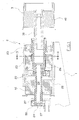
- the figures illustrate a carousel 1 of a printing machine, supported and driven by known means which are not illustrated.
- groups 2 are arranged which comprise the chucks bearing objects to be printed, in the example plastic containers denoted by 3.
- the groups 2 comprise an external casing 20 provided with flanges 21 on a base for fixing the groups onto the carousel.
- the groups 2 are radially orientated and fastened to the carousel at equidistant positions.
- the bearings support, rotatingly but axially fixed, a single axially-hollow shaft 24 along almost an entire length of the shaft 24.
- the hollow shaft 24 exhibits a section located inside a stator coil 25 of an electrical motor. On the section thereof which is adjacent to the stator 25, the shaft 24 comprises a series of equidistant permanent magnets 26.
- the assembly of the hollow shaft, and relative permanent magnets, and the stator coil form a controlled speed and travel brushless motor.
- the motor develops at least 500 W of power and has a speed of from just above zero to 2000 rpm.
- the terminal portion of the hollow shaft is accessible axially from the outside of the casing and forms a seating for housing and fixing a coaxial adapter shaft 30, axially perforated and fastened to the shaft by mechanical means, and bearing the chuck 40 at an end thereof
- the chuck 40 pneumatically retains a container 3 to be printed.
- the shaft 24, the shaft 30 and the chuck 40 are made of steel, and the casing is made of aluminium or an equivalent alloy.
- the hollow shaft 24 is closed and extends into a pneumatic distributor 50 with which the shaft 24 communicates through radial holes 27.
- the shaft cavity is in communication via the distributor 50 with means under depression.
- the shaft 24 can be assembled from a plurality of aligned parts, joined by a screw-coupling.
- the end of the hollow shaft adjacent to the means under depression is associated to an encoder device 60, of known type, which precisely controls the rate of rotation of the shaft and sends signals to the motor control and command circuit which controls the current in the stator coil 25.
- controller of commercially-available type is used.
- the motor control and command circuit is also of known type and consequently is not illustrated.
- the device functions as follows.
- the carousel 1 advances in steps, positioning containers 3 below the printing station one at a time, such that they are tangentially aligned with the print matrix.
- the containers 3 are retained on the chuck by the depression created through the axial cavity of the shaft and the pneumatic distributor 50.
- the brushless motor comprising the stator coil 25 rotates the container at a controlled velocity such that the peripheral velocity of the container is the same as the peripheral velocity of the print roller.
- the print roller can be powered using various means, all of known type, including coupling with a brushless type motor which offers precision control over rotation times and velocities.
Landscapes
- Engineering & Computer Science (AREA)
- Mechanical Engineering (AREA)
- Screen Printers (AREA)
- Connection Of Motors, Electrical Generators, Mechanical Devices, And The Like (AREA)
- Permanent Magnet Type Synchronous Machine (AREA)
- Inking, Control Or Cleaning Of Printing Machines (AREA)
- Brushless Motors (AREA)
Claims (7)
- Motorisierte spannvorrichtungstragende Gruppe (2) für eine Druckmaschine, wobei die spannvorrichtungstragende Gruppe (2) von einem bürstenlosen Motor angetrieben wird, der ein Gehäuse (20) umfasst, in dem eine Statorspule (25) und ein Rotor angeordnet sind, wobei der Rotor mit Hilfe einer Steuerschaltung, die eine Codiervorrichtung (60) umfasst, sowohl in Hinsicht auf Geschwindigkeit als auch auf Betätigungszeiten gesteuert wird, dadurch gekennzeichnet, dass die Motorwelle (24) am Außenumfang verteilte Dauermagneten (26) trägt und im Inneren des Gehäuses (20) an die Codiervorrichtung (60) gekoppelt ist und sich außerhalb des Gehäuses (20) derart erstreckt, dass eine Spannvorrichtung (40) getragen wird, die ein zu bedruckendes Objekt (30) dreht.
- Motorisierte Gruppe (2) nach Anspruch 1, dadurch gekennzeichnet, dass die Welle (24) hohl ist und über einen pneumatischen Verteiler (50) mit Mitteln zum Erzeugen eines Drucks gekoppelt ist.
- Motorisierte Gruppe (2) nach Anspruch 1, dadurch gekennzeichnet, dass die Welle (24) mit Hilfe zweier Kugellager (22, 23) an dem Gehäuse (20) getragen wird, wobei das erste Kugellager (22) nahe einem offenen Ende des Gehäuses (20) angeordnet ist, das zweite Kugellager (23) innerhalb des Gehäuses (20) angeordnet ist und das Gehäuse (20) die Statorschaltung (25) des Motors zwischen den Kugellagern (22, 23) trägt.
- Motorisierte Gruppe (2) nach Anspruch 3, dadurch gekennzeichnet, dass sich die Welle (24) derart über das zweite Kugellager (23) hervorstehend erstreckt, dass die Codiervorrichtung (60) im Inneren des Gehäuses (20) getragen ist.
- Motorisierte Gruppe (2) nach Anspruch 3, dadurch gekennzeichnet, dass die Motorwelle (24) axial hohl ist und sich auf der Codiervorrichtungsseite über das Gehäuse (20) hinaus erstreckt, wo die Welle (24) über einen rotierenden Verteiler mit Mitteln unter Druck verbunden ist.
- Motorisierte Gruppe (2) nach Anspruch 5, dadurch gekennzeichnet, dass die hohle Motorwelle (24) aus mehreren ausgerichteten Abschnitten konstruiert ist.
- Motorisierte Gruppe (2) nach Anspruch 6, dadurch gekennzeichnet, dass die ausgerichteten Abschnitte der Welle (24) durch eine Schraubverbindung miteinander verbunden sind.
Applications Claiming Priority (1)
| Application Number | Priority Date | Filing Date | Title |
|---|---|---|---|
| ITRE2009A000058A IT1394326B1 (it) | 2009-06-15 | 2009-06-15 | Gruppo motorizzato porta mandrino per macchina da stampa |
Publications (2)
| Publication Number | Publication Date |
|---|---|
| EP2263877A1 EP2263877A1 (de) | 2010-12-22 |
| EP2263877B1 true EP2263877B1 (de) | 2014-04-23 |
Family
ID=41402561
Family Applications (1)
| Application Number | Title | Priority Date | Filing Date |
|---|---|---|---|
| EP10165735.1A Active EP2263877B1 (de) | 2009-06-15 | 2010-06-11 | Motorisierte Dornhaltereinheit für eine Druckmaschine |
Country Status (4)
| Country | Link |
|---|---|
| US (1) | US8110953B2 (de) |
| EP (1) | EP2263877B1 (de) |
| CN (1) | CN101920594B (de) |
| IT (1) | IT1394326B1 (de) |
Families Citing this family (4)
| Publication number | Priority date | Publication date | Assignee | Title |
|---|---|---|---|---|
| EP2136456B1 (de) * | 2008-06-19 | 2012-09-12 | SICK STEGMANN GmbH | Bausatz-Servomotor |
| ITBO20130578A1 (it) * | 2013-10-18 | 2015-04-19 | Phizero S R L | Metodo e macchina per preparare un contenitore contenente una sostanza attiva |
| CN108297003B (zh) * | 2018-01-29 | 2020-06-05 | 湖州龙溢机械有限公司 | 一种汽车零件生产用智能夹持装置 |
| US12512739B2 (en) | 2023-05-25 | 2025-12-30 | Goodrich Corporation | Brushless motor with integrated position sensor |
Family Cites Families (17)
| Publication number | Priority date | Publication date | Assignee | Title |
|---|---|---|---|---|
| US2578953A (en) * | 1949-10-13 | 1951-12-18 | Fessler Machine Company | Metal strip uncoiler |
| US2909338A (en) * | 1955-04-01 | 1959-10-20 | Erwin Loewy | Mandrel arrangement |
| GB1137712A (en) * | 1964-12-03 | 1968-12-27 | Dawson Payne & Elliott Ltd | Machines or apparatus for feeding, preparing, printing and delivering hollow articles |
| US3950199A (en) * | 1974-03-15 | 1976-04-13 | Owens-Illinois, Inc. | Bottle coating method |
| US4423880A (en) * | 1981-02-23 | 1984-01-03 | Cooper Industries, Inc. | Hydraulic chuck |
| EP0257136B1 (de) * | 1986-07-18 | 1993-05-19 | FECO Engineered Systems, Inc. | Drehbare und zurückziehbare Haltevorrichtung für Behälter und Förderer dafür |
| US4949023A (en) * | 1988-10-27 | 1990-08-14 | Shlien David J | Direct current machine with switchable stator windings |
| US5111742A (en) * | 1990-08-13 | 1992-05-12 | Sequa Corporation | Mandrel trip subassembly for continuous motion can decorators |
| US5481910A (en) * | 1993-07-30 | 1996-01-09 | Gei Systems, Inc. | Adjustable spindle |
| JPH08168210A (ja) * | 1994-12-12 | 1996-06-25 | Olympus Optical Co Ltd | エンコーダーユニット、制御モーター、制御モーターの組立方法 |
| JP2000216133A (ja) * | 1999-01-21 | 2000-08-04 | Sony Corp | ウエハ処理装置 |
| FR2802145B1 (fr) * | 1999-12-14 | 2002-09-06 | Dubuit Mach | Ensemble rotatif constitue d'un porte-objet et de son support, en particulier pour machine a imprimer, et machine a imprimer equipee d'un tel ensemble |
| ITPR20030015A1 (it) * | 2003-03-04 | 2004-09-05 | Fermac Srl | Macchina da stampa serigrafica. |
| FR2891194B1 (fr) * | 2005-09-28 | 2007-11-30 | Cer Soc Par Actions Simplifiee | Machine de marquage d'un objet cylindrique et procedes mis en oeuvre avec une telle machine |
| PL1782951T3 (pl) * | 2005-11-03 | 2008-05-30 | Ball Europe Gmbh | Trzpień naprężający stosowany w druku cyfrowym |
| ITRE20060017A1 (it) * | 2006-02-10 | 2007-08-11 | Omso Officina Macchine Per Stampa Su Oggetti | Dispositivo per trasferire un oggetto dal mandrino di una macchina da stampa ad un piolo di supporto e allontanamento |
| CN101401609B (zh) * | 2008-09-24 | 2011-03-09 | 宁波鑫盛达机械有限公司 | 冰淇淋制作加盖机构 |
-
2009
- 2009-06-15 IT ITRE2009A000058A patent/IT1394326B1/it active
-
2010
- 2010-06-11 EP EP10165735.1A patent/EP2263877B1/de active Active
- 2010-06-15 US US12/815,549 patent/US8110953B2/en active Active
- 2010-06-17 CN CN201010206767.1A patent/CN101920594B/zh active Active
Also Published As
| Publication number | Publication date |
|---|---|
| ITRE20090058A1 (it) | 2010-12-16 |
| IT1394326B1 (it) | 2012-06-06 |
| EP2263877A1 (de) | 2010-12-22 |
| CN101920594A (zh) | 2010-12-22 |
| US8110953B2 (en) | 2012-02-07 |
| CN101920594B (zh) | 2014-11-05 |
| US20100313776A1 (en) | 2010-12-16 |
| HK1151004A1 (en) | 2012-01-20 |
Similar Documents
| Publication | Publication Date | Title |
|---|---|---|
| EP2263876B1 (de) | Drehbares Karussell für Rotationsdruckmaschinen | |
| JP5449141B2 (ja) | 容器を処理するための直接駆動装置を有する機械 | |
| US7497323B2 (en) | Machine for aligning and equipping articles | |
| US8955665B2 (en) | Container treatment machine | |
| EP2263877B1 (de) | Motorisierte Dornhaltereinheit für eine Druckmaschine | |
| US20080156442A1 (en) | Machine for labeling containers | |
| CA2492796A1 (en) | Apparatus and method for applying labels to a container | |
| CN101679011A (zh) | 用于灌装机器的转盘的组合驱动装置 | |
| US20110147169A1 (en) | Container transporting device | |
| JP5659132B2 (ja) | 中空円筒体を再成形する装置および方法 | |
| US20080127757A1 (en) | Drive Device | |
| EP2608902B1 (de) | Materialzuführvorrichtung in rollenbauart | |
| EP1504998B1 (de) | Etikettiervorrichtung | |
| US6490969B2 (en) | Machine for printing or otherwise decorating hollow bodies | |
| US6550385B1 (en) | Cam-independent drive for folding components | |
| EP3517460B1 (de) | Flachelementzuführvorrichtung | |
| JP2013501686A (ja) | 容器取り扱い機械 | |
| CN103372888A (zh) | 用于薄膜管的直接驱动的旋转刀具 | |
| HK1151004B (en) | A powered chuck-bearing group for a printing machine | |
| JP2006334776A (ja) | 工作機械のクランプ装置 | |
| JP6494042B2 (ja) | 中空円筒体を形成する装置及び方法 | |
| US7562625B2 (en) | Apparatus and method for generating an electric current for a press cylinder | |
| JP7598832B2 (ja) | 信号授受装置および処理装置 | |
| HK1151014B (en) | A rotating carousel for rotary printing machines | |
| EP4106155A1 (de) | Magnetischer motor |
Legal Events
| Date | Code | Title | Description |
|---|---|---|---|
| PUAI | Public reference made under article 153(3) epc to a published international application that has entered the european phase |
Free format text: ORIGINAL CODE: 0009012 |
|
| AK | Designated contracting states |
Kind code of ref document: A1 Designated state(s): AL AT BE BG CH CY CZ DE DK EE ES FI FR GB GR HR HU IE IS IT LI LT LU LV MC MK MT NL NO PL PT RO SE SI SK SM TR |
|
| AX | Request for extension of the european patent |
Extension state: BA ME RS |
|
| RAP1 | Party data changed (applicant data changed or rights of an application transferred) |
Owner name: DECOMAC - SOCIETA'A RESPONSABILITA' LIMITATA |
|
| 17P | Request for examination filed |
Effective date: 20110603 |
|
| GRAP | Despatch of communication of intention to grant a patent |
Free format text: ORIGINAL CODE: EPIDOSNIGR1 |
|
| RIC1 | Information provided on ipc code assigned before grant |
Ipc: B41F 15/20 20060101AFI20131127BHEP Ipc: B41F 17/00 20060101ALI20131127BHEP Ipc: B41F 17/18 20060101ALI20131127BHEP |
|
| INTG | Intention to grant announced |
Effective date: 20131213 |
|
| GRAS | Grant fee paid |
Free format text: ORIGINAL CODE: EPIDOSNIGR3 |
|
| GRAA | (expected) grant |
Free format text: ORIGINAL CODE: 0009210 |
|
| AK | Designated contracting states |
Kind code of ref document: B1 Designated state(s): AL AT BE BG CH CY CZ DE DK EE ES FI FR GB GR HR HU IE IS IT LI LT LU LV MC MK MT NL NO PL PT RO SE SI SK SM TR |
|
| REG | Reference to a national code |
Ref country code: GB Ref legal event code: FG4D |
|
| REG | Reference to a national code |
Ref country code: CH Ref legal event code: EP |
|
| REG | Reference to a national code |
Ref country code: AT Ref legal event code: REF Ref document number: 663555 Country of ref document: AT Kind code of ref document: T Effective date: 20140515 |
|
| REG | Reference to a national code |
Ref country code: IE Ref legal event code: FG4D |
|
| REG | Reference to a national code |
Ref country code: DE Ref legal event code: R096 Ref document number: 602010015313 Country of ref document: DE Effective date: 20140605 |
|
| REG | Reference to a national code |
Ref country code: CH Ref legal event code: NV Representative=s name: ISLER AND PEDRAZZINI AG, CH |
|
| REG | Reference to a national code |
Ref country code: NL Ref legal event code: T3 |
|
| REG | Reference to a national code |
Ref country code: LT Ref legal event code: MG4D |
|
| PG25 | Lapsed in a contracting state [announced via postgrant information from national office to epo] |
Ref country code: GR Free format text: LAPSE BECAUSE OF FAILURE TO SUBMIT A TRANSLATION OF THE DESCRIPTION OR TO PAY THE FEE WITHIN THE PRESCRIBED TIME-LIMIT Effective date: 20140724 Ref country code: CY Free format text: LAPSE BECAUSE OF FAILURE TO SUBMIT A TRANSLATION OF THE DESCRIPTION OR TO PAY THE FEE WITHIN THE PRESCRIBED TIME-LIMIT Effective date: 20140423 Ref country code: IS Free format text: LAPSE BECAUSE OF FAILURE TO SUBMIT A TRANSLATION OF THE DESCRIPTION OR TO PAY THE FEE WITHIN THE PRESCRIBED TIME-LIMIT Effective date: 20140823 Ref country code: NO Free format text: LAPSE BECAUSE OF FAILURE TO SUBMIT A TRANSLATION OF THE DESCRIPTION OR TO PAY THE FEE WITHIN THE PRESCRIBED TIME-LIMIT Effective date: 20140723 Ref country code: BG Free format text: LAPSE BECAUSE OF FAILURE TO SUBMIT A TRANSLATION OF THE DESCRIPTION OR TO PAY THE FEE WITHIN THE PRESCRIBED TIME-LIMIT Effective date: 20140723 Ref country code: FI Free format text: LAPSE BECAUSE OF FAILURE TO SUBMIT A TRANSLATION OF THE DESCRIPTION OR TO PAY THE FEE WITHIN THE PRESCRIBED TIME-LIMIT Effective date: 20140423 Ref country code: LT Free format text: LAPSE BECAUSE OF FAILURE TO SUBMIT A TRANSLATION OF THE DESCRIPTION OR TO PAY THE FEE WITHIN THE PRESCRIBED TIME-LIMIT Effective date: 20140423 |
|
| PG25 | Lapsed in a contracting state [announced via postgrant information from national office to epo] |
Ref country code: PL Free format text: LAPSE BECAUSE OF FAILURE TO SUBMIT A TRANSLATION OF THE DESCRIPTION OR TO PAY THE FEE WITHIN THE PRESCRIBED TIME-LIMIT Effective date: 20140423 Ref country code: SE Free format text: LAPSE BECAUSE OF FAILURE TO SUBMIT A TRANSLATION OF THE DESCRIPTION OR TO PAY THE FEE WITHIN THE PRESCRIBED TIME-LIMIT Effective date: 20140423 Ref country code: HR Free format text: LAPSE BECAUSE OF FAILURE TO SUBMIT A TRANSLATION OF THE DESCRIPTION OR TO PAY THE FEE WITHIN THE PRESCRIBED TIME-LIMIT Effective date: 20140423 Ref country code: LV Free format text: LAPSE BECAUSE OF FAILURE TO SUBMIT A TRANSLATION OF THE DESCRIPTION OR TO PAY THE FEE WITHIN THE PRESCRIBED TIME-LIMIT Effective date: 20140423 Ref country code: ES Free format text: LAPSE BECAUSE OF FAILURE TO SUBMIT A TRANSLATION OF THE DESCRIPTION OR TO PAY THE FEE WITHIN THE PRESCRIBED TIME-LIMIT Effective date: 20140423 |
|
| PG25 | Lapsed in a contracting state [announced via postgrant information from national office to epo] |
Ref country code: PT Free format text: LAPSE BECAUSE OF FAILURE TO SUBMIT A TRANSLATION OF THE DESCRIPTION OR TO PAY THE FEE WITHIN THE PRESCRIBED TIME-LIMIT Effective date: 20140825 |
|
| REG | Reference to a national code |
Ref country code: DE Ref legal event code: R097 Ref document number: 602010015313 Country of ref document: DE |
|
| PG25 | Lapsed in a contracting state [announced via postgrant information from national office to epo] |
Ref country code: EE Free format text: LAPSE BECAUSE OF FAILURE TO SUBMIT A TRANSLATION OF THE DESCRIPTION OR TO PAY THE FEE WITHIN THE PRESCRIBED TIME-LIMIT Effective date: 20140423 Ref country code: RO Free format text: LAPSE BECAUSE OF FAILURE TO SUBMIT A TRANSLATION OF THE DESCRIPTION OR TO PAY THE FEE WITHIN THE PRESCRIBED TIME-LIMIT Effective date: 20140423 Ref country code: LU Free format text: LAPSE BECAUSE OF FAILURE TO SUBMIT A TRANSLATION OF THE DESCRIPTION OR TO PAY THE FEE WITHIN THE PRESCRIBED TIME-LIMIT Effective date: 20140611 Ref country code: BE Free format text: LAPSE BECAUSE OF FAILURE TO SUBMIT A TRANSLATION OF THE DESCRIPTION OR TO PAY THE FEE WITHIN THE PRESCRIBED TIME-LIMIT Effective date: 20140423 Ref country code: CZ Free format text: LAPSE BECAUSE OF FAILURE TO SUBMIT A TRANSLATION OF THE DESCRIPTION OR TO PAY THE FEE WITHIN THE PRESCRIBED TIME-LIMIT Effective date: 20140423 Ref country code: SK Free format text: LAPSE BECAUSE OF FAILURE TO SUBMIT A TRANSLATION OF THE DESCRIPTION OR TO PAY THE FEE WITHIN THE PRESCRIBED TIME-LIMIT Effective date: 20140423 Ref country code: MC Free format text: LAPSE BECAUSE OF FAILURE TO SUBMIT A TRANSLATION OF THE DESCRIPTION OR TO PAY THE FEE WITHIN THE PRESCRIBED TIME-LIMIT Effective date: 20140423 Ref country code: DK Free format text: LAPSE BECAUSE OF FAILURE TO SUBMIT A TRANSLATION OF THE DESCRIPTION OR TO PAY THE FEE WITHIN THE PRESCRIBED TIME-LIMIT Effective date: 20140423 |
|
| PLBE | No opposition filed within time limit |
Free format text: ORIGINAL CODE: 0009261 |
|
| STAA | Information on the status of an ep patent application or granted ep patent |
Free format text: STATUS: NO OPPOSITION FILED WITHIN TIME LIMIT |
|
| REG | Reference to a national code |
Ref country code: IE Ref legal event code: MM4A |
|
| 26N | No opposition filed |
Effective date: 20150126 |
|
| PG25 | Lapsed in a contracting state [announced via postgrant information from national office to epo] |
Ref country code: IE Free format text: LAPSE BECAUSE OF NON-PAYMENT OF DUE FEES Effective date: 20140611 |
|
| REG | Reference to a national code |
Ref country code: DE Ref legal event code: R097 Ref document number: 602010015313 Country of ref document: DE Effective date: 20150126 |
|
| PG25 | Lapsed in a contracting state [announced via postgrant information from national office to epo] |
Ref country code: SI Free format text: LAPSE BECAUSE OF FAILURE TO SUBMIT A TRANSLATION OF THE DESCRIPTION OR TO PAY THE FEE WITHIN THE PRESCRIBED TIME-LIMIT Effective date: 20140423 |
|
| PG25 | Lapsed in a contracting state [announced via postgrant information from national office to epo] |
Ref country code: MT Free format text: LAPSE BECAUSE OF FAILURE TO SUBMIT A TRANSLATION OF THE DESCRIPTION OR TO PAY THE FEE WITHIN THE PRESCRIBED TIME-LIMIT Effective date: 20140423 |
|
| PG25 | Lapsed in a contracting state [announced via postgrant information from national office to epo] |
Ref country code: SM Free format text: LAPSE BECAUSE OF FAILURE TO SUBMIT A TRANSLATION OF THE DESCRIPTION OR TO PAY THE FEE WITHIN THE PRESCRIBED TIME-LIMIT Effective date: 20140423 |
|
| REG | Reference to a national code |
Ref country code: FR Ref legal event code: PLFP Year of fee payment: 7 |
|
| PG25 | Lapsed in a contracting state [announced via postgrant information from national office to epo] |
Ref country code: TR Free format text: LAPSE BECAUSE OF FAILURE TO SUBMIT A TRANSLATION OF THE DESCRIPTION OR TO PAY THE FEE WITHIN THE PRESCRIBED TIME-LIMIT Effective date: 20140423 Ref country code: HU Free format text: LAPSE BECAUSE OF FAILURE TO SUBMIT A TRANSLATION OF THE DESCRIPTION OR TO PAY THE FEE WITHIN THE PRESCRIBED TIME-LIMIT; INVALID AB INITIO Effective date: 20100611 |
|
| REG | Reference to a national code |
Ref country code: FR Ref legal event code: PLFP Year of fee payment: 8 |
|
| REG | Reference to a national code |
Ref country code: FR Ref legal event code: PLFP Year of fee payment: 9 |
|
| PG25 | Lapsed in a contracting state [announced via postgrant information from national office to epo] |
Ref country code: MK Free format text: LAPSE BECAUSE OF FAILURE TO SUBMIT A TRANSLATION OF THE DESCRIPTION OR TO PAY THE FEE WITHIN THE PRESCRIBED TIME-LIMIT Effective date: 20140423 |
|
| PG25 | Lapsed in a contracting state [announced via postgrant information from national office to epo] |
Ref country code: AL Free format text: LAPSE BECAUSE OF FAILURE TO SUBMIT A TRANSLATION OF THE DESCRIPTION OR TO PAY THE FEE WITHIN THE PRESCRIBED TIME-LIMIT Effective date: 20140423 |
|
| PGFP | Annual fee paid to national office [announced via postgrant information from national office to epo] |
Ref country code: DE Payment date: 20250627 Year of fee payment: 16 |
|
| PGFP | Annual fee paid to national office [announced via postgrant information from national office to epo] |
Ref country code: GB Payment date: 20250627 Year of fee payment: 16 |
|
| PGFP | Annual fee paid to national office [announced via postgrant information from national office to epo] |
Ref country code: NL Payment date: 20250626 Year of fee payment: 16 Ref country code: IT Payment date: 20250428 Year of fee payment: 16 |
|
| PGFP | Annual fee paid to national office [announced via postgrant information from national office to epo] |
Ref country code: FR Payment date: 20250625 Year of fee payment: 16 |
|
| PGFP | Annual fee paid to national office [announced via postgrant information from national office to epo] |
Ref country code: AT Payment date: 20250521 Year of fee payment: 16 |
|
| PGFP | Annual fee paid to national office [announced via postgrant information from national office to epo] |
Ref country code: CH Payment date: 20250701 Year of fee payment: 16 |