EP2264268B2 - Crémone serrure - Google Patents
Crémone serrure Download PDFInfo
- Publication number
- EP2264268B2 EP2264268B2 EP10159286.3A EP10159286A EP2264268B2 EP 2264268 B2 EP2264268 B2 EP 2264268B2 EP 10159286 A EP10159286 A EP 10159286A EP 2264268 B2 EP2264268 B2 EP 2264268B2
- Authority
- EP
- European Patent Office
- Prior art keywords
- ejector
- drive
- control slide
- slide
- lock
- Prior art date
- Legal status (The legal status is an assumption and is not a legal conclusion. Google has not performed a legal analysis and makes no representation as to the accuracy of the status listed.)
- Active
Links
Images




Classifications
-
- E—FIXED CONSTRUCTIONS
- E05—LOCKS; KEYS; WINDOW OR DOOR FITTINGS; SAFES
- E05B—LOCKS; ACCESSORIES THEREFOR; HANDCUFFS
- E05B63/00—Locks or fastenings with special structural characteristics
- E05B63/24—Arrangements in which the fastening members which engage one another are mounted respectively on the wing and the frame and are both movable, e.g. for release by moving either of them
-
- E—FIXED CONSTRUCTIONS
- E05—LOCKS; KEYS; WINDOW OR DOOR FITTINGS; SAFES
- E05C—BOLTS OR FASTENING DEVICES FOR WINGS, SPECIALLY FOR DOORS OR WINDOWS
- E05C7/00—Fastening devices specially adapted for two wings
- E05C7/04—Fastening devices specially adapted for two wings for wings which abut when closed
-
- E—FIXED CONSTRUCTIONS
- E05—LOCKS; KEYS; WINDOW OR DOOR FITTINGS; SAFES
- E05B—LOCKS; ACCESSORIES THEREFOR; HANDCUFFS
- E05B47/00—Operating or controlling locks or other fastening devices by electric or magnetic means
- E05B47/0001—Operating or controlling locks or other fastening devices by electric or magnetic means with electric actuators; Constructional features thereof
- E05B2047/0014—Constructional features of actuators or power transmissions therefor
- E05B2047/0015—Output elements of actuators
- E05B2047/0016—Output elements of actuators with linearly reciprocating motion
-
- E—FIXED CONSTRUCTIONS
- E05—LOCKS; KEYS; WINDOW OR DOOR FITTINGS; SAFES
- E05B—LOCKS; ACCESSORIES THEREFOR; HANDCUFFS
- E05B47/00—Operating or controlling locks or other fastening devices by electric or magnetic means
- E05B47/0001—Operating or controlling locks or other fastening devices by electric or magnetic means with electric actuators; Constructional features thereof
- E05B47/0012—Operating or controlling locks or other fastening devices by electric or magnetic means with electric actuators; Constructional features thereof with rotary electromotors
-
- E—FIXED CONSTRUCTIONS
- E05—LOCKS; KEYS; WINDOW OR DOOR FITTINGS; SAFES
- E05B—LOCKS; ACCESSORIES THEREFOR; HANDCUFFS
- E05B65/00—Locks or fastenings for special use
- E05B65/10—Locks or fastenings for special use for panic or emergency doors
-
- E—FIXED CONSTRUCTIONS
- E05—LOCKS; KEYS; WINDOW OR DOOR FITTINGS; SAFES
- E05C—BOLTS OR FASTENING DEVICES FOR WINGS, SPECIALLY FOR DOORS OR WINDOWS
- E05C9/00—Arrangements of simultaneously actuated bolts or other securing devices at well-separated positions on the same wing
- E05C9/04—Arrangements of simultaneously actuated bolts or other securing devices at well-separated positions on the same wing with two sliding bars moved in opposite directions when fastening or unfastening
- E05C9/041—Arrangements of simultaneously actuated bolts or other securing devices at well-separated positions on the same wing with two sliding bars moved in opposite directions when fastening or unfastening with rack and pinion mechanism
Definitions
- the invention relates to a drive bolt lock for a door having an active leaf, with a latch ejector, a control slide that can be displaced parallel to a faceplate, a latch ejector drive driven by the control slide, and a retraction slide for a drive rod.
- active leaf and inactive leaf locking systems are usually used. So-called espagnolette locks are used on the passive leaf side.
- the passive leaf lock When the passive leaf lock is actuated in a panic, the upper and lower driving bar rods are retracted and at the same time the latch and the bolt of the active leaf lock are pushed back into the lock case via the release slide so that the door system can be opened.
- the EP-A-1 947 273 shows such a shoot bolt lock which, when actuated, simultaneously pushes out the latch and pulls in the upper and lower drive rods. With this lock, only the complete passive leaf can be released. It is not possible that only the active leaf is released via the espagnolette lock, whereas the passive leaf remains locked via the espagnolette.
- the invention is based on the object of providing a shoot bolt lock which can be actuated electrically and with which either only the active leaf or both leaves can be released, depending on the requirements.
- a coupling element is advantageously provided which, when the control slide is actuated, drives the draw-in slide with a time delay.
- the latch of the active leaf lock is first pushed out of the shooting bolt lock so that the inactive leaf remains locked via the connecting rod or the connecting rods.
- the drive rods are then unlocked in a second work step so that the inactive leaf is completely unlocked. It can now also be opened. According to the invention, this is achieved in that the extension of the latch and the retraction of the drive rods take place one after the other.
- the espagnolette lock according to the invention can not only be operated manually by means of a handle but can also be controlled by a motor.
- the sequential motor-driven shoot bolt lock thus divides the overall sequence of movements when the lock is actuated into two sequences of movements running one behind the other.
- the latch and, if necessary, a bolt of the active leaf lock are pushed out via the ejector (s) during the first movement, which is necessary e.g. for the use of access control systems or the automated opening of the active leaf.
- the espagnolette rods are drawn in, which is necessary for the additional release of the inactive leaf.
- the electric opener can be saved with the invention and both the upper and lower drive bar rods can be used.
- control slide has an idle position opposite the coupling member and an adjoining driver section.
- a bolt ejector and a bolt ejector drive driven by the control slide are preferably also provided. This means that a locked active leaf lock can also be unlocked by sliding the bolt out of the espagnolette lock.
- the shooting bolt lock provides a handle follower and a follower pivot lever which is driven directly or via a transmission gear and which drives the control slide or the latch ejector drive.
- the espagnolette lock can be operated manually not only by actuating the control slide but also by means of a lever handle. By depressing the handle more or less far, only the latch is pushed out or the entire espagnolette lock is unlocked and the inactive leaf can be swiveled open.
- the nut pivot lever is from a gear section is formed or has at least one gear portion.
- the trigger movement can directly drive the latch ejector drive or the movement can be translated by means of a gear so that even small trigger movements are sufficient to extend the latch.
- the control slide In order to block the control slide in the rest position of the shoot bolt lock and thereby lock the drive rods in their extended position, the control slide has an edge recess into which a locking bolt of the latch ejector and / or the bolt ejector engages when the latch ejector and / or the The bolt ejector assumes its pushed-in position.
- the latch ejector drive has a control cam and a guide pin guided in the control cam.
- the control cam is provided in the control slide or in the ejector drive and the guide pin is arranged on the control slide or on the ejector drive.
- an exemplary embodiment of the espagnolette lock provides that the coupling member has a gearwheel which meshes with the draw-in slide and which is driven by a toothed rack section of the control slide.
- the toothed rack section of the control slide is at a distance from the gearwheel when idling, so that it is not actuated.
- the driver section adjoining the idle is formed by the rack section.
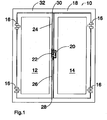
- a door designated as a whole with 10 which has an inactive leaf 12 and an active leaf 14. Both the inactive leaf 12 and the active leaf 14 are pivotably connected to a frame 18 via hinges 16.
- the active leaf 14 can be locked to the active leaf 12 via a lock 20 and the inactive leaf 12 has a espagnolette lock 22 to which an upper drive rod 24 and a lower drive rod 26 are coupled.
- the lower drive rod 26 engages with its downwardly facing free end 28 in the ground and the upper drive rod 24 engages with its upwardly facing free end 30 in the crossbeam 32 of the frame 18.
- the lock 20 and the espagnolette lock 22 are opposite one another, so that the latch of the lock 20 engages in the espagnolette lock 22.
- the bolt of the lock 20 also engages in the shoot bolt lock 22.
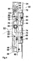
- the Figure 2 shows the espagnolette lock 22 without the housing cover, the espagnolette lock 22 being screwed to a cuff 34.
- a control slide 36 which has a shoulder 38 protruding from the lower end of the housing of the espagnolette lock 22.
- a drive motor for example, via which the control slide 36 is displaced vertically, that is to say in the longitudinal direction of the espagnolette lock 22 or parallel to the cuff 34 and in the direction of the arrow 92, can act on this projection 38.
- the control slide 36 has a driver section 40 in the form of a rack section 42.
- a latch ejector drive 44 can also be seen, which is pivotably mounted in the shoot bolt lock 22 via a pivot bearing 46.
- a bolt ejector drive 48 is provided, which is also pivotably mounted via a pivot bearing 50.
- the two ejector drives 44 and 48 are essentially double-armed, with a pin being arranged on each arm 52, 54, which engages in a horizontal elongated hole 56, 58 in the control slide 36.
- the other arm 60, 62 is each configured like a link and rests on a roller 64, 66 of a latch ejector 68 or a bolt ejector 70.
- the roller 64 is located on a shoulder 72 and the roller 66 is located in a recess 74 of the control slide 36. In this position of the latch ejector 68 or of the bolt ejector 70, the control slide 36 is blocked against displacement in the direction of the arrow 92.
- the latch ejector drive 44 is provided with a toothed ring section 76 which extends between the two arms 52 and 60.
- a gearwheel portion 78 of a nut pivot lever 80 which is rotatably connected to a follower 82, meshes with this gear rim portion 76.
- the handle follower 82 takes in the Figure 2 their basic position, in which a pusher 84, only hinted at, protrudes horizontally.
- FIG 3 is that in the Figure 2
- the shooting bolt lock 22 shown is shown in which the handle 84 is pivoted downwards by about 15 ° so that it assumes an intermediate position.
- the nut pivot lever 80 in particular its gear section 78, meshes with the ring gear section 76 of the latch ejector drive 44, the upper arm 60 sliding along the roller 64 and thereby displacing the latch ejector 68 in the direction of the cuff 34.
- the latch ejector 68 assumes its almost completely displaced position in which it has completely pushed a latch engaging in the espagnolette lock 22 out of the espagnolette lock 22.
- the displacement movements of the latch ejector 68 and the bolt ejector 70 are also caused by the fact that the extension 38 is moved in the direction of the arrow 92, for example by means of a motor drive.
- the pusher 84 is pivoted by approx. 30 ° from the horizontal into its end position, whereby the nut pivot lever 80 and with it the gear wheel section 78 is also pivoted further than in the position according to FIG Figure 3 .
- the toothed ring section 76 meshing with the gear section 78 is also pivoted further, as a result of which the latch ejector drive 44 is rotated further clockwise and the latch ejector 68 is thereby pushed slightly further out of the housing of the shoot bolt lock 22.
- This is achieved in that the roller 64 is moved slightly further in the direction of the cuff 34 via the second arm 60.
- the second arm 60 holds the roller 64 in position.
- the control slide 36 is displaced further in the direction of the gear 90 or in the direction of the arrow 92, so that the rack section 42 now meshes with the gear 90.
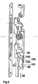
- a retraction slide 94 Via the gear 90, which is now driven, a retraction slide 94, the rack 96 of which, with respect to the gear 90, is opposite the rack section 42, is drawn into the housing of the espagnolette lock 22.
- the upper drive rod 24 is fastened to the draw-in slide 94, so that it is displaced in the direction of the drive bolt lock 22 and released by the transverse bar 32.
- Moving the control slide 36 in the direction of the arrow 92 also causes the pin 88 to be entrained via the elongated hole 58, so that the bolt ejector drive 48 is also rotated further in the clockwise direction.
- gear wheel 90 and the rack drive 42 form a coupling member 104 which has an idle mode in which a movement of the rack section 42 does not cause any movement of the gear wheel 90 (movement of the control slide from the position shown in FIG Figure 2 position shown in the Figure 3 shown intermediate position).
- the gear 90 is driven.
- the nose 102 and the bending tab 100 represent a coupling member 106, with a movement of the control slide 36 from the one shown in FIG Figure 2 position shown in the Figure 3
- the intermediate position shown in which the bending tab 100 is only moved within the recess 101, does not cause any displacement of the draw-in slide 98.
- the illustrated end position of the control slide 36 takes the bending tab 100 with it, the nose 102 and thus the draw-in slide 98. In this way, the lower drive rod 26 is moved in the direction of arrow 92 and pulled out of the ground, since the drive rod 26 is fastened to the draw-in slide 98.
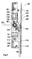
- the Figures 6 to 9 show a second exemplary embodiment in which the control slide 36 can also be driven by a motor via the extension 38 in the direction of the arrow 92.
- the control slide 36 In its lower region, the control slide 36 has a control cam 108 with an inclined section 110 and a section 112 oriented parallel to the direction of displacement of the control slide 36 according to arrow 92.
- a pin 114 which protrudes from the bolt ejector 70, is guided in this control cam 108.
- a pin 116 protrudes therefrom, which engages in a control cam 118 which is provided in the latch ejector 68.
- the control cam 118 also has an inclined section 120 and a section 122 oriented parallel to the direction of displacement of the control slide 36 according to arrow 92. Both the latch ejector 68 and the bolt ejector 70 are guided via horizontally arranged guide elements 124 in such a way that they can only be moved in the direction of the faceplate 34.
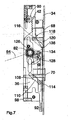
- the pivoting lever 80 of the follower 82 carries on its free, pivotable end a gear 128 which meshes with an internal tooth segment 130 fixed in place in the espagnolette lock 22.
- a toothed ring 126 engages in the toothed wheel 128 and is connected to a control lever 132 which can be pivoted about the axis of the handle follower 82.
- This control lever 132 is in the Figure 7 almost completely covered by the nut pivot lever 80, in the Figure 8 however, shown fully visible, since it has been pivoted through a larger pivot angle.
- At the free end of the control lever 132 there is a control pin 134 which engages in a horizontal groove 136 of the control slide 36.
- the nut pivot lever 80, the gear wheel 128, the internal tooth segment 130, the ring gear 126 and the control lever 132 form a transmission gear 138 with which the rotary movement of the nut 82 is translated to a larger, for example twice or three times the angle of rotation for the control lever 132.
- control slide 36 is instead of the trigger 84 by a motor by means of slide 36 in the direction of arrow 92 in the Figure 7
- the pin 114 is displaced by the inclined section 110 in the control cam 108, and as a result the bolt ejector 70 is displaced in the direction of the faceplate 34.
- the pin 116 is displaced in the inclined section 120 of the control cam 118, as a result of which the latch ejector 68 is also displaced in the direction of the faceplate 34.
- the control pin 134 is carried along via the groove 136 in the control slide 36 which is displaced in the direction of the arrow 92, as a result of which the control lever 132 is pivoted counterclockwise.
- the Figure 8 shows the control slide 36 in the completely shifted position in the direction of arrow 92, in which the latch ejector 68 and the bolt ejector 70 are still pushed out, since the pin 114 along the vertical section 112 of the control cam 108 and the pin 116 along the vertical Section 122 of the control cam 118 are displaced, and thereby no additional displacement is effected.
- the rack section 42 drives the gear 90, as a result of which the rack 96 of the draw-in slide 94 is displaced against the direction of the arrow 92 and the draw-in slide 94 is drawn in.
- a drive rod 24 attached to the draw-in slide 94 is thus also drawn in.
- the control slide 36 is also displaced when, by means of a pusher 84, the pusher follower 82 is moved from the rest position according to FIG Figure 6 in the intermediate layer according to Figure 7 and from there to the end position according to Figure 8 , in which the inactive leaf 12 can be opened, is rotated.
Landscapes
- Engineering & Computer Science (AREA)
- Mechanical Engineering (AREA)
- Physics & Mathematics (AREA)
- Electromagnetism (AREA)
- Structural Engineering (AREA)
- Lock And Its Accessories (AREA)
- Moulds For Moulding Plastics Or The Like (AREA)
Claims (13)
- Serrure crémone (22) pour une porte (10) présentant un vantail de service (14), comprenant un éjecteur de pêne demi-tour (68), un coulisseau de commande (36) déplaçable parallèlement à une têtière (34), un entraînement d'éjecteur de pêne demi-tour (44) entraîné par ledit coulisseau de commande (36) ainsi qu'un coulisseau de rétraction (94, 98) pour une tringle d'entraînement (24, 26), caractérisée par le fait que, lorsque ledit coulisseau de commande (36) est actionné, d'abord le pêne d'une serrure à vantail de service (20) est poussé hors de la serrure crémone au moyen de l'éjecteur de pêne demi-tour (68) et, ensuite, ledit coulisseau de rétraction (94, 98) est entraîné.
- Serrure crémone selon la revendication 1, caractérisée par le fait qu'un organe de couplage (104, 106) est prévu qui, lorsque ledit coulisseau de commande (36) est actionné, entraîne ledit coulisseau de rétraction (94, 98) avec un retard dans le temps.
- Serrure crémone selon la revendication 1 ou 2, caractérisée par le fait que ledit coulisseau de commande (36) présente, par rapport audit organe de couplage (104, 106), une marche à vide et une section d'entraînement (40) y contiguë.
- Serrure crémone selon l'une quelconque des revendications précédentes, caractérisée par le fait qu'un éjecteur de pêne (70) et un entraînement d'éjecteur de pêne (48) entraîné par ledit coulisseau de commande (36) sont prévus, en particulier ledit éjecteur de pêne (70) et ledit éjecteur de pêne demi-tour (68) étant entrainés simultanément.
- Serrure crémone selon l'une quelconque des revendications précédentes, caractérisée par un fouillot (82) et par un levier de pivotement de fouillot (80) qui est entraîné directement ou via un engrenage multiplicateur (138) et qui entraîne le coulisseau de commande (36) ou ledit entraînement d'éjecteur de pêne demi-tour (44).
- Serrure crémone selon la revendication 5, caractérisée par le fait que ledit levier de pivotement de fouillot (80) est constitué par une section de roue dentée (78) ou, au moins, présente une section de roue dentée.
- Serrure crémone selon la revendication 6, caractérisée par le fait que la section de roue dentée (78) engrène avec une section de couronne dentée (76) de l'entraînement d'éjecteur de pêne demi-tour (44) ou d'un engrenage multiplicateur (138).
- Serrure crémone selon l'une quelconque des revendications précédentes, caractérisée par le fait que ledit coulisseau de commande (36) présente un évidement marginal (72, 74) dans lequel s'engage un élément (64, 66) de l'éjecteur de pêne demi-tour (68) et/ou d'un éjecteur de pêne (70) lorsque ledit éjecteur de pêne demi-tour (68) et/ou ledit éjecteur de pêne (70) prend sa position rentrée.
- Serrure crémone selon l'une quelconque des revendications précédentes, caractérisée par le fait que ledit entraînement d'éjecteur de pêne demi-tour (44) présente une came de commande (118) et un tenon de guidage (116) guidé dans ladite came de commande (118).
- Serrure crémone selon la revendication 9, caractérisée par le fait que ladite came de commande (118) est prévue dans ledit coulisseau de commande (36) ou dans ledit entraînement d'éjecteur (44).
- Serrure crémone selon la revendication 9 ou 10, caractérisée par le fait que ledit tenon de guidage (116) est disposé sur ledit coulisseau de commande (36) ou sur ledit entraînement d'éjecteur (44).
- Serrure crémone selon l'une quelconque des revendications précédentes, caractérisée par le fait que ledit organe de couplage (104) présente une roue dentée (90) qui engrène avec ledit coulisseau de rétraction (94) et qui est entraînée par une portion de crémaillère (42) du coulisseau de commande (36).
- Serrure crémone selon la revendication 12, caractérisée par le fait que, en marche à vide, ladite portion de crémaillère (42) du coulisseau de commande (36) présente une distance par rapport à la roue dentée (90) et la section d'entraînement (40) y contiguë est constituée par ladite portion de crémaillère (42).
Applications Claiming Priority (1)
| Application Number | Priority Date | Filing Date | Title |
|---|---|---|---|
| DE102009025469A DE102009025469B3 (de) | 2009-06-15 | 2009-06-15 | Treibriegelschloss |
Publications (4)
| Publication Number | Publication Date |
|---|---|
| EP2264268A2 EP2264268A2 (fr) | 2010-12-22 |
| EP2264268A3 EP2264268A3 (fr) | 2013-03-20 |
| EP2264268B1 EP2264268B1 (fr) | 2013-12-04 |
| EP2264268B2 true EP2264268B2 (fr) | 2021-11-10 |
Family
ID=42937176
Family Applications (1)
| Application Number | Title | Priority Date | Filing Date |
|---|---|---|---|
| EP10159286.3A Active EP2264268B2 (fr) | 2009-06-15 | 2010-04-08 | Crémone serrure |
Country Status (2)
| Country | Link |
|---|---|
| EP (1) | EP2264268B2 (fr) |
| DE (1) | DE102009025469B3 (fr) |
Cited By (1)
| Publication number | Priority date | Publication date | Assignee | Title |
|---|---|---|---|---|
| DE102024107450A1 (de) * | 2024-03-15 | 2025-09-18 | Assa Abloy Sicherheitstechnik Gmbh | Treibriegelschloss mit Mittelstellung |
Families Citing this family (10)
| Publication number | Priority date | Publication date | Assignee | Title |
|---|---|---|---|---|
| CN102268952B (zh) * | 2011-06-20 | 2013-02-20 | 江苏河谷矿业科技发展有限公司 | 煤矿井下用气囊式密封舱门 |
| DE102012111881B4 (de) | 2012-12-06 | 2021-12-30 | WILKA Schließtechnik GmbH | Motorisch betreibbares Standflügelschloss mit Riegel- und Fallenauswerfer |
| EP2749721B1 (fr) | 2012-12-28 | 2016-08-24 | BKS GmbH | Crémone espagnolette |
| DE102015110503A1 (de) * | 2014-06-30 | 2015-12-31 | Assa Abloy Sicherheitstechnik Gmbh | Passivflügelschloss |
| DE102015115830A1 (de) * | 2014-09-19 | 2016-03-24 | Assa Abloy Sicherheitstechnik Gmbh | Tageshebel |
| DE102015000605A1 (de) * | 2015-01-16 | 2016-07-21 | Assa Abloy Sicherheitstechnik Gmbh | Schlosseinrichtung für eine Tür oder ein Fenster |
| DE102017208721A1 (de) * | 2017-05-23 | 2018-11-29 | Geze Gmbh | Gegenkasten für ein Paniktürschloss |
| DE102018106832A1 (de) * | 2018-03-22 | 2019-09-26 | Dormakaba Deutschland Gmbh | Gegenschloss für eine Standflügeltür |
| ES2906213T3 (es) * | 2019-02-28 | 2022-04-13 | Talleres De Escoriaza S A U | Contracerradura para hoja pasiva para una puerta de doble hoja |
| DE102024107451A1 (de) * | 2024-03-15 | 2025-09-18 | Assa Abloy Sicherheitstechnik Gmbh | Treibriegelschloss mit Hubumschaltung |
Citations (5)
| Publication number | Priority date | Publication date | Assignee | Title |
|---|---|---|---|---|
| DE8413327U1 (de) † | 1984-05-02 | 1987-03-26 | Carl Fuhr Gmbh & Co, 5628 Heiligenhaus | Treibstangenbeschlag |
| EP0858541A2 (fr) † | 1995-10-31 | 1998-08-19 | HÖRMANN KG Freisen | Dispositif de verrouillage |
| EP1557514A1 (fr) † | 2004-01-21 | 2005-07-27 | WILKA SCHLIESSTECHNIK GmbH | Crémone-serrure pour porte à double battants avec fonction anti-panique |
| DE102004009973A1 (de) † | 2004-03-01 | 2005-09-29 | Wilh. Schlechtendahl & Söhne GmbH & Co KG | Gegenkasten für ein Paniktürschloß |
| EP1703051A1 (fr) † | 2005-02-22 | 2006-09-20 | BKS GmbH | Serrure encastrée |
Family Cites Families (5)
| Publication number | Priority date | Publication date | Assignee | Title |
|---|---|---|---|---|
| DE3636236A1 (de) * | 1986-10-24 | 1988-04-28 | Betz Gmbh & Co Kg Geb | Panikverschluss fuer zweifluegelige tueren |
| DE9409846U1 (de) * | 1994-06-21 | 1994-09-15 | Bks Gmbh, 42549 Velbert | Panik-Treibstangenschloß |
| DE19652601C1 (de) * | 1996-12-18 | 1998-06-25 | Dorma Gmbh & Co Kg | Ent- und Verriegelung für eine einen Standflügel und einen Gangflügel aufweisende Tür |
| DE102005015248B4 (de) * | 2005-04-02 | 2010-01-21 | Wilka Schließtechnik GmbH | Standflügelschloss mit einem elektrischen Türöffner |
| DE202007000599U1 (de) * | 2007-01-10 | 2007-03-15 | Kfv Karl Fliether Gmbh & Co. Kg | Verriegelungsbeschlag |
-
2009
- 2009-06-15 DE DE102009025469A patent/DE102009025469B3/de active Active
-
2010
- 2010-04-08 EP EP10159286.3A patent/EP2264268B2/fr active Active
Patent Citations (5)
| Publication number | Priority date | Publication date | Assignee | Title |
|---|---|---|---|---|
| DE8413327U1 (de) † | 1984-05-02 | 1987-03-26 | Carl Fuhr Gmbh & Co, 5628 Heiligenhaus | Treibstangenbeschlag |
| EP0858541A2 (fr) † | 1995-10-31 | 1998-08-19 | HÖRMANN KG Freisen | Dispositif de verrouillage |
| EP1557514A1 (fr) † | 2004-01-21 | 2005-07-27 | WILKA SCHLIESSTECHNIK GmbH | Crémone-serrure pour porte à double battants avec fonction anti-panique |
| DE102004009973A1 (de) † | 2004-03-01 | 2005-09-29 | Wilh. Schlechtendahl & Söhne GmbH & Co KG | Gegenkasten für ein Paniktürschloß |
| EP1703051A1 (fr) † | 2005-02-22 | 2006-09-20 | BKS GmbH | Serrure encastrée |
Cited By (2)
| Publication number | Priority date | Publication date | Assignee | Title |
|---|---|---|---|---|
| DE102024107450A1 (de) * | 2024-03-15 | 2025-09-18 | Assa Abloy Sicherheitstechnik Gmbh | Treibriegelschloss mit Mittelstellung |
| EP4624705A1 (fr) | 2024-03-15 | 2025-10-01 | ASSA ABLOY Sicherheitstechnik GmbH | Procédé pour actionner une serrure à pêne dormant à position centrale d'une porte à deux battants et serrure à pêne dormant à position centrale pour une porte à deux battants |
Also Published As
| Publication number | Publication date |
|---|---|
| EP2264268A3 (fr) | 2013-03-20 |
| EP2264268B1 (fr) | 2013-12-04 |
| EP2264268A2 (fr) | 2010-12-22 |
| DE102009025469B3 (de) | 2011-04-14 |
Similar Documents
| Publication | Publication Date | Title |
|---|---|---|
| EP2264268B1 (fr) | Crémone serrure | |
| EP1932989B1 (fr) | Système de fermeture pour portes, fenêtres ou analogues, en particulier crémone-serrure à fonction d'urgence et de verrouillage à plusieurs points | |
| DE3447748C2 (fr) | ||
| EP0942135B2 (fr) | Dispositif de verrouillage | |
| EP1970507B1 (fr) | Serrure anti-panique | |
| EP0545899B1 (fr) | Crémone-serrure | |
| EP1932990A2 (fr) | Système de fermeture pour portes, fenêtres ou analogues, en particulier crémone-serrure à fonction d'urgence et de verrouillage à plusieurs points | |
| EP2749721B1 (fr) | Crémone espagnolette | |
| EP0798436A2 (fr) | Dispositif de verrouillage | |
| EP0945572B1 (fr) | Ensemble de serrure de porte, de préférence crémone-serrure | |
| EP1574644A2 (fr) | Système de verrouillage pour portes, fenêtres ou similaires, notamment crémone-serrure avec fonction anti-panique et avec plusieurs points de condamnation | |
| EP0833997B1 (fr) | Dispositif de fermeture a organe d'arret du battant d'une porte | |
| DE102022100121A1 (de) | Selbstverriegelndes Schloss mit motorischer Entriegelung | |
| EP2072725A2 (fr) | Crémone-serrure | |
| EP2339096B1 (fr) | Serrure à crémone dotée d'une fonction anti-panique et d'un verrouillage multiple | |
| EP3907357B1 (fr) | Dispositif de verrouillage | |
| DE202006001383U1 (de) | Treibriegelschloß | |
| DE102015000606A1 (de) | Verriegelungsvorrichtung für einen schwenkbar gelagerten Flügel | |
| EP3628801B1 (fr) | Dispositif de fermeture pour une porte et procédé pour ouvrir une porte | |
| EP1672153B1 (fr) | Serrure avec pêne dormant et dispositif de commande du pêne dormant | |
| EP2322744A1 (fr) | Serrure, serrure à crochet pivotant et système de verrouillage, notamment pour le verrouillage à plusieurs points d'une porte ou d'une fenêtre | |
| AT392819B (de) | Schloss, insbesondere panikschloss | |
| DE102018115985A1 (de) | Schlossgegenkasten für ein Aktivflügelschloss mit Falzluftausgleich | |
| EP2453086B1 (fr) | Ferrure de crémone pour battant fixe de fenêtres ou de portes à deux vantaux sans montant médian | |
| AT509508B1 (de) | Mitnehmer zur montage im oberen türfalz eines stehflügels einer zweiflügeligen tür |
Legal Events
| Date | Code | Title | Description |
|---|---|---|---|
| PUAI | Public reference made under article 153(3) epc to a published international application that has entered the european phase |
Free format text: ORIGINAL CODE: 0009012 |
|
| AK | Designated contracting states |
Kind code of ref document: A2 Designated state(s): AT BE BG CH CY CZ DE DK EE ES FI FR GB GR HR HU IE IS IT LI LT LU LV MC MK MT NL NO PL PT RO SE SI SK SM TR |
|
| AX | Request for extension of the european patent |
Extension state: AL BA ME RS |
|
| PUAL | Search report despatched |
Free format text: ORIGINAL CODE: 0009013 |
|
| AK | Designated contracting states |
Kind code of ref document: A3 Designated state(s): AT BE BG CH CY CZ DE DK EE ES FI FR GB GR HR HU IE IS IT LI LT LU LV MC MK MT NL NO PL PT RO SE SI SK SM TR |
|
| AX | Request for extension of the european patent |
Extension state: AL BA ME RS |
|
| RIC1 | Information provided on ipc code assigned before grant |
Ipc: E05B 63/24 20060101ALI20130208BHEP Ipc: E05C 7/04 20060101ALI20130208BHEP Ipc: E05C 9/00 20060101AFI20130208BHEP Ipc: E05B 65/10 20060101ALI20130208BHEP |
|
| 17P | Request for examination filed |
Effective date: 20130311 |
|
| GRAP | Despatch of communication of intention to grant a patent |
Free format text: ORIGINAL CODE: EPIDOSNIGR1 |
|
| INTG | Intention to grant announced |
Effective date: 20130704 |
|
| GRAS | Grant fee paid |
Free format text: ORIGINAL CODE: EPIDOSNIGR3 |
|
| GRAA | (expected) grant |
Free format text: ORIGINAL CODE: 0009210 |
|
| AK | Designated contracting states |
Kind code of ref document: B1 Designated state(s): AT BE BG CH CY CZ DE DK EE ES FI FR GB GR HR HU IE IS IT LI LT LU LV MC MK MT NL NO PL PT RO SE SI SK SM TR |
|
| REG | Reference to a national code |
Ref country code: GB Ref legal event code: FG4D Free format text: NOT ENGLISH |
|
| REG | Reference to a national code |
Ref country code: CH Ref legal event code: NV Representative=s name: DREISS PATENTANWAELTE, DE Ref country code: CH Ref legal event code: EP |
|
| REG | Reference to a national code |
Ref country code: IE Ref legal event code: FG4D Free format text: LANGUAGE OF EP DOCUMENT: GERMAN Ref country code: AT Ref legal event code: REF Ref document number: 643638 Country of ref document: AT Kind code of ref document: T Effective date: 20140115 |
|
| REG | Reference to a national code |
Ref country code: DE Ref legal event code: R096 Ref document number: 502010005536 Country of ref document: DE Effective date: 20140130 |
|
| REG | Reference to a national code |
Ref country code: NL Ref legal event code: T3 |
|
| REG | Reference to a national code |
Ref country code: CH Ref legal event code: PFA Owner name: BKS GMBH, DE Free format text: FORMER OWNER: BKS GMBH, DE |
|
| PG25 | Lapsed in a contracting state [announced via postgrant information from national office to epo] |
Ref country code: FI Free format text: LAPSE BECAUSE OF FAILURE TO SUBMIT A TRANSLATION OF THE DESCRIPTION OR TO PAY THE FEE WITHIN THE PRESCRIBED TIME-LIMIT Effective date: 20131204 Ref country code: NO Free format text: LAPSE BECAUSE OF FAILURE TO SUBMIT A TRANSLATION OF THE DESCRIPTION OR TO PAY THE FEE WITHIN THE PRESCRIBED TIME-LIMIT Effective date: 20140304 Ref country code: LT Free format text: LAPSE BECAUSE OF FAILURE TO SUBMIT A TRANSLATION OF THE DESCRIPTION OR TO PAY THE FEE WITHIN THE PRESCRIBED TIME-LIMIT Effective date: 20131204 Ref country code: HR Free format text: LAPSE BECAUSE OF FAILURE TO SUBMIT A TRANSLATION OF THE DESCRIPTION OR TO PAY THE FEE WITHIN THE PRESCRIBED TIME-LIMIT Effective date: 20131204 Ref country code: SE Free format text: LAPSE BECAUSE OF FAILURE TO SUBMIT A TRANSLATION OF THE DESCRIPTION OR TO PAY THE FEE WITHIN THE PRESCRIBED TIME-LIMIT Effective date: 20131204 |
|
| REG | Reference to a national code |
Ref country code: LT Ref legal event code: MG4D |
|
| PG25 | Lapsed in a contracting state [announced via postgrant information from national office to epo] |
Ref country code: CY Free format text: LAPSE BECAUSE OF FAILURE TO SUBMIT A TRANSLATION OF THE DESCRIPTION OR TO PAY THE FEE WITHIN THE PRESCRIBED TIME-LIMIT Effective date: 20131204 Ref country code: LV Free format text: LAPSE BECAUSE OF FAILURE TO SUBMIT A TRANSLATION OF THE DESCRIPTION OR TO PAY THE FEE WITHIN THE PRESCRIBED TIME-LIMIT Effective date: 20131204 |
|
| PG25 | Lapsed in a contracting state [announced via postgrant information from national office to epo] |
Ref country code: IS Free format text: LAPSE BECAUSE OF FAILURE TO SUBMIT A TRANSLATION OF THE DESCRIPTION OR TO PAY THE FEE WITHIN THE PRESCRIBED TIME-LIMIT Effective date: 20140404 Ref country code: EE Free format text: LAPSE BECAUSE OF FAILURE TO SUBMIT A TRANSLATION OF THE DESCRIPTION OR TO PAY THE FEE WITHIN THE PRESCRIBED TIME-LIMIT Effective date: 20131204 |
|
| PG25 | Lapsed in a contracting state [announced via postgrant information from national office to epo] |
Ref country code: ES Free format text: LAPSE BECAUSE OF FAILURE TO SUBMIT A TRANSLATION OF THE DESCRIPTION OR TO PAY THE FEE WITHIN THE PRESCRIBED TIME-LIMIT Effective date: 20131204 Ref country code: RO Free format text: LAPSE BECAUSE OF FAILURE TO SUBMIT A TRANSLATION OF THE DESCRIPTION OR TO PAY THE FEE WITHIN THE PRESCRIBED TIME-LIMIT Effective date: 20131204 Ref country code: PT Free format text: LAPSE BECAUSE OF FAILURE TO SUBMIT A TRANSLATION OF THE DESCRIPTION OR TO PAY THE FEE WITHIN THE PRESCRIBED TIME-LIMIT Effective date: 20140404 Ref country code: CZ Free format text: LAPSE BECAUSE OF FAILURE TO SUBMIT A TRANSLATION OF THE DESCRIPTION OR TO PAY THE FEE WITHIN THE PRESCRIBED TIME-LIMIT Effective date: 20131204 Ref country code: SK Free format text: LAPSE BECAUSE OF FAILURE TO SUBMIT A TRANSLATION OF THE DESCRIPTION OR TO PAY THE FEE WITHIN THE PRESCRIBED TIME-LIMIT Effective date: 20131204 Ref country code: PL Free format text: LAPSE BECAUSE OF FAILURE TO SUBMIT A TRANSLATION OF THE DESCRIPTION OR TO PAY THE FEE WITHIN THE PRESCRIBED TIME-LIMIT Effective date: 20131204 |
|
| REG | Reference to a national code |
Ref country code: DE Ref legal event code: R026 Ref document number: 502010005536 Country of ref document: DE |
|
| PLBI | Opposition filed |
Free format text: ORIGINAL CODE: 0009260 |
|
| 26 | Opposition filed |
Opponent name: ASSA ABLOY SICHERHEITSTECHNIK GMBH Effective date: 20140902 |
|
| PLAX | Notice of opposition and request to file observation + time limit sent |
Free format text: ORIGINAL CODE: EPIDOSNOBS2 |
|
| PG25 | Lapsed in a contracting state [announced via postgrant information from national office to epo] |
Ref country code: DK Free format text: LAPSE BECAUSE OF FAILURE TO SUBMIT A TRANSLATION OF THE DESCRIPTION OR TO PAY THE FEE WITHIN THE PRESCRIBED TIME-LIMIT Effective date: 20131204 |
|
| REG | Reference to a national code |
Ref country code: DE Ref legal event code: R026 Ref document number: 502010005536 Country of ref document: DE Effective date: 20140902 |
|
| PG25 | Lapsed in a contracting state [announced via postgrant information from national office to epo] |
Ref country code: LU Free format text: LAPSE BECAUSE OF FAILURE TO SUBMIT A TRANSLATION OF THE DESCRIPTION OR TO PAY THE FEE WITHIN THE PRESCRIBED TIME-LIMIT Effective date: 20140408 Ref country code: MC Free format text: LAPSE BECAUSE OF FAILURE TO SUBMIT A TRANSLATION OF THE DESCRIPTION OR TO PAY THE FEE WITHIN THE PRESCRIBED TIME-LIMIT Effective date: 20131204 |
|
| GBPC | Gb: european patent ceased through non-payment of renewal fee |
Effective date: 20140408 |
|
| REG | Reference to a national code |
Ref country code: FR Ref legal event code: ST Effective date: 20141231 |
|
| PLBB | Reply of patent proprietor to notice(s) of opposition received |
Free format text: ORIGINAL CODE: EPIDOSNOBS3 |
|
| REG | Reference to a national code |
Ref country code: IE Ref legal event code: MM4A |
|
| PG25 | Lapsed in a contracting state [announced via postgrant information from national office to epo] |
Ref country code: GB Free format text: LAPSE BECAUSE OF NON-PAYMENT OF DUE FEES Effective date: 20140408 |
|
| REG | Reference to a national code |
Ref country code: CH Ref legal event code: PCAR Free format text: NEW ADDRESS: FRIEDERICHSTR. 6, 70174 STUTTGART (DE) |
|
| PG25 | Lapsed in a contracting state [announced via postgrant information from national office to epo] |
Ref country code: FR Free format text: LAPSE BECAUSE OF NON-PAYMENT OF DUE FEES Effective date: 20140430 Ref country code: SI Free format text: LAPSE BECAUSE OF FAILURE TO SUBMIT A TRANSLATION OF THE DESCRIPTION OR TO PAY THE FEE WITHIN THE PRESCRIBED TIME-LIMIT Effective date: 20131204 |
|
| REG | Reference to a national code |
Ref country code: CH Ref legal event code: PCAR Free format text: NEW ADDRESS: FRIEDRICHSTR. 6, 70174 STUTTGART (DE) |
|
| PG25 | Lapsed in a contracting state [announced via postgrant information from national office to epo] |
Ref country code: IT Free format text: LAPSE BECAUSE OF FAILURE TO SUBMIT A TRANSLATION OF THE DESCRIPTION OR TO PAY THE FEE WITHIN THE PRESCRIBED TIME-LIMIT Effective date: 20131204 |
|
| PG25 | Lapsed in a contracting state [announced via postgrant information from national office to epo] |
Ref country code: IE Free format text: LAPSE BECAUSE OF NON-PAYMENT OF DUE FEES Effective date: 20140408 |
|
| PG25 | Lapsed in a contracting state [announced via postgrant information from national office to epo] |
Ref country code: MT Free format text: LAPSE BECAUSE OF FAILURE TO SUBMIT A TRANSLATION OF THE DESCRIPTION OR TO PAY THE FEE WITHIN THE PRESCRIBED TIME-LIMIT Effective date: 20131204 |
|
| PG25 | Lapsed in a contracting state [announced via postgrant information from national office to epo] |
Ref country code: SM Free format text: LAPSE BECAUSE OF FAILURE TO SUBMIT A TRANSLATION OF THE DESCRIPTION OR TO PAY THE FEE WITHIN THE PRESCRIBED TIME-LIMIT Effective date: 20131204 |
|
| PG25 | Lapsed in a contracting state [announced via postgrant information from national office to epo] |
Ref country code: BG Free format text: LAPSE BECAUSE OF FAILURE TO SUBMIT A TRANSLATION OF THE DESCRIPTION OR TO PAY THE FEE WITHIN THE PRESCRIBED TIME-LIMIT Effective date: 20131204 Ref country code: GR Free format text: LAPSE BECAUSE OF FAILURE TO SUBMIT A TRANSLATION OF THE DESCRIPTION OR TO PAY THE FEE WITHIN THE PRESCRIBED TIME-LIMIT Effective date: 20140305 |
|
| PG25 | Lapsed in a contracting state [announced via postgrant information from national office to epo] |
Ref country code: TR Free format text: LAPSE BECAUSE OF FAILURE TO SUBMIT A TRANSLATION OF THE DESCRIPTION OR TO PAY THE FEE WITHIN THE PRESCRIBED TIME-LIMIT Effective date: 20131204 Ref country code: HU Free format text: LAPSE BECAUSE OF FAILURE TO SUBMIT A TRANSLATION OF THE DESCRIPTION OR TO PAY THE FEE WITHIN THE PRESCRIBED TIME-LIMIT; INVALID AB INITIO Effective date: 20100408 |
|
| APBM | Appeal reference recorded |
Free format text: ORIGINAL CODE: EPIDOSNREFNO |
|
| APBP | Date of receipt of notice of appeal recorded |
Free format text: ORIGINAL CODE: EPIDOSNNOA2O |
|
| APAH | Appeal reference modified |
Free format text: ORIGINAL CODE: EPIDOSCREFNO |
|
| APBM | Appeal reference recorded |
Free format text: ORIGINAL CODE: EPIDOSNREFNO |
|
| APBP | Date of receipt of notice of appeal recorded |
Free format text: ORIGINAL CODE: EPIDOSNNOA2O |
|
| APBQ | Date of receipt of statement of grounds of appeal recorded |
Free format text: ORIGINAL CODE: EPIDOSNNOA3O |
|
| PG25 | Lapsed in a contracting state [announced via postgrant information from national office to epo] |
Ref country code: MK Free format text: LAPSE BECAUSE OF FAILURE TO SUBMIT A TRANSLATION OF THE DESCRIPTION OR TO PAY THE FEE WITHIN THE PRESCRIBED TIME-LIMIT Effective date: 20131204 |
|
| APBU | Appeal procedure closed |
Free format text: ORIGINAL CODE: EPIDOSNNOA9O |
|
| PUAH | Patent maintained in amended form |
Free format text: ORIGINAL CODE: 0009272 |
|
| STAA | Information on the status of an ep patent application or granted ep patent |
Free format text: STATUS: PATENT MAINTAINED AS AMENDED |
|
| 27A | Patent maintained in amended form |
Effective date: 20211110 |
|
| AK | Designated contracting states |
Kind code of ref document: B2 Designated state(s): AT BE BG CH CY CZ DE DK EE ES FI FR GB GR HR HU IE IS IT LI LT LU LV MC MK MT NL NO PL PT RO SE SI SK SM TR |
|
| REG | Reference to a national code |
Ref country code: DE Ref legal event code: R102 Ref document number: 502010005536 Country of ref document: DE |
|
| REG | Reference to a national code |
Ref country code: NL Ref legal event code: FP |
|
| REG | Reference to a national code |
Ref country code: DE Ref legal event code: R082 Ref document number: 502010005536 Country of ref document: DE |
|
| P01 | Opt-out of the competence of the unified patent court (upc) registered |
Effective date: 20230509 |
|
| REG | Reference to a national code |
Ref country code: CH Ref legal event code: U11 Free format text: ST27 STATUS EVENT CODE: U-0-0-U10-U11 (AS PROVIDED BY THE NATIONAL OFFICE) Effective date: 20260501 |
|
| PGFP | Annual fee paid to national office [announced via postgrant information from national office to epo] |
Ref country code: NL Payment date: 20260420 Year of fee payment: 17 |
|
| PGFP | Annual fee paid to national office [announced via postgrant information from national office to epo] |
Ref country code: DE Payment date: 20260422 Year of fee payment: 17 |
|
| PGFP | Annual fee paid to national office [announced via postgrant information from national office to epo] |
Ref country code: AT Payment date: 20260421 Year of fee payment: 17 |
|
| PGFP | Annual fee paid to national office [announced via postgrant information from national office to epo] |
Ref country code: BE Payment date: 20260420 Year of fee payment: 17 Ref country code: CH Payment date: 20260501 Year of fee payment: 17 |