EP2264832B1 - Réflecteur secondaire pour une antenne à double réflecteur - Google Patents
Réflecteur secondaire pour une antenne à double réflecteur Download PDFInfo
- Publication number
- EP2264832B1 EP2264832B1 EP10164928.3A EP10164928A EP2264832B1 EP 2264832 B1 EP2264832 B1 EP 2264832B1 EP 10164928 A EP10164928 A EP 10164928A EP 2264832 B1 EP2264832 B1 EP 2264832B1
- Authority
- EP
- European Patent Office
- Prior art keywords
- secondary reflector
- reflector
- horn
- waveguide
- diameter
- Prior art date
- Legal status (The legal status is an assumption and is not a legal conclusion. Google has not performed a legal analysis and makes no representation as to the accuracy of the status listed.)
- Active
Links
Images

Classifications
-
- H—ELECTRICITY
- H01—ELECTRIC ELEMENTS
- H01Q—ANTENNAS, i.e. RADIO AERIALS
- H01Q19/00—Combinations of primary active antenna elements and units with secondary devices, e.g. with quasi-optical devices, for giving the antenna a desired directional characteristic
- H01Q19/10—Combinations of primary active antenna elements and units with secondary devices, e.g. with quasi-optical devices, for giving the antenna a desired directional characteristic using reflecting surfaces
- H01Q19/18—Combinations of primary active antenna elements and units with secondary devices, e.g. with quasi-optical devices, for giving the antenna a desired directional characteristic using reflecting surfaces having two or more spaced reflecting surfaces
- H01Q19/19—Combinations of primary active antenna elements and units with secondary devices, e.g. with quasi-optical devices, for giving the antenna a desired directional characteristic using reflecting surfaces having two or more spaced reflecting surfaces comprising one main concave reflecting surface associated with an auxiliary reflecting surface
- H01Q19/193—Combinations of primary active antenna elements and units with secondary devices, e.g. with quasi-optical devices, for giving the antenna a desired directional characteristic using reflecting surfaces having two or more spaced reflecting surfaces comprising one main concave reflecting surface associated with an auxiliary reflecting surface with feed supported subreflector
Definitions
- the present invention relates to radio frequency (RF) antennas with dual reflectors.
- These antennas comprise a concave primary reflector of large diameter and a secondary reflector ("sub-reflector" in English) convex of smaller diameter located near the focus of the primary reflector.
- These antennas operate indifferently in transmitter mode or in receiver mode, corresponding to two opposite directions of RF wave propagation.
- the description is given either in transmission mode or in reception mode of the antenna, according to which allows to better illustrate the described phenomena. It should be noted that all the reasonings apply to the antennas as well in reception as in emission.
- Double reflector antennas are used to produce compact systems.
- the double reflectors comprise a concave primary reflector, usually parabolic, and a convex secondary reflector of smaller diameter which is placed in the vicinity of the focus, on the same axis of revolution as the primary reflector.
- the primary reflector is pierced at its top and a waveguide is inserted along its axis. The end of the waveguide faces the secondary reflector. In transmission mode, the RF waves transmitted by the waveguide are reflected by the secondary reflector to the primary reflector.
- the secondary reflector must be maintained in the vicinity of the focus of the primary reflector.
- One of the possible ways is to fix the secondary reflector at the end of the waveguide, then serving as a mechanical support.
- the secondary reflector usually comprises a dielectric body (frequently plastic) substantially conical and transparent to RF waves.
- the outer surface of substantially conical general shape of the secondary reflector faces the primary reflector.
- the convex inner surface of the secondary reflector is coated with a treatment for reflecting the RF waves in direction of the primary reflector through the dielectric body. This coating is usually made of metal. Multiple reflections of RF waves occur between the end of the waveguide and the primary reflector, involving the secondary reflector.
- the overflow losses In the antenna transmission mode, for example, the overflow losses, expressed in dB, correspond to the energy reflected by the secondary reflector towards the primary reflector, and whose path ends beyond the outer diameter of the reflector. primary. These losses lead to pollution of the environment by RF waves. These overflow losses should be limited to levels defined by standards.
- a first proposed solution is to attach to the periphery of the primary reflector a skirt which has the shape of a cylinder, of diameter close to that of the primary reflector and of suitable height, lined internally with a layer absorbing RF radiation.
- this known solution has the inconvenient today troublesome cost of the material of the skirt, as well as the cost of assembling this skirt on the primary reflector.
- Another solution is to provide a secondary reflector whose outer surface has a profile according to a particular curve.
- this solution allows a low overflow loss value only if the secondary reflector has a large size.
- the reflection losses are reduced only for a narrow frequency band. Indeed, the waveguide produces a large beam of radiation with a low gain.
- the secondary reflector In order to reduce overflow losses, the secondary reflector must therefore have a large diameter or be placed very close to the waveguide. However, in the latter case, the performance relating to the reflection loss is affected.
- the document US 6724349 proposes to provide the inside of the waveguide transverse sections of different diameter and to provide on the convex surface of the secondary reflector faces perpendicular to its axis.
- the object of the present invention is to propose a secondary reflector of a double reflector antenna whose overflow losses are significantly reduced, without presenting the drawbacks of the prior art, particularly in terms of size and cost.
- the overflow losses for the transmission mode of an RF antenna correspond to values of the illumination angle (measured with respect to the axis of revolution of the secondary reflector) of the primary reflector by the secondary reflector for which RF waves from the waveguide are reflected by the secondary reflector in a direction which is outside the perimeter of the primary reflector.
- the object of the present invention is a dual reflector antenna secondary reflector according to claim 1.
- the outer surface of the horn has a substantially linear profile and the horn has substantially the shape of a truncated cone.
- the constant A is different from zero (A ⁇ 0).
- the outer surface of the horn has a continuous profile of particular shape.
- the horn has better efficiency, lower cross polarization, side lobes having a lower level and a frequency band of increased width.
- the outer surface of the horn is metallized. It may for example be covered with a reflective metal, such as silver.
- the invention also proposes a double reflector antenna comprising a secondary reflector as previously described.
- the invention has the advantage of significantly reducing the losses by overflow and to have low losses by reflection.
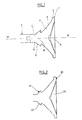
- a secondary reflector 1 of a double reflector antenna connected to a waveguide 2 .
- the waveguide 2 is here a hollow metal tube, for example aluminum. Its diameter, about ⁇ g / 2.5 where ⁇ g is the wavelength of the guided RF signal, is chosen so as to allow propagation of the TE11 mode only, before the appearance of higher modes.
- the secondary reflector 1 comprises a dielectric body 3 whose end 4 of smaller diameter is connected to the waveguide 2 .
- the dielectric body 3 of the secondary reflector 1 is for example a dielectric material such as plastic.
- the opposite end 5 of the dielectric body 3 is dug to form a reflective inner concave surface 6 for the RF signal.
- the inner surface 6 of the secondary reflector 1 is for example a surface of revolution described by a polynomial equation around an axis of revolution W-W '
- the inner surface 6 may be covered with a reflecting metal, such as silver.
- the outer surface 7 of the secondary reflector 1 is the surface placed facing the primary reflector.
- the outer surface 7 is a surface of revolution about the axis of revolution WW ".
- the end 4 of the dielectric body 3 of the secondary reflector 1 is externally provided with a bulge, here in the shape of a truncated cone, forming a horn 8 ("horn" in English) whose outer surface 9 has a continuous profile.
- the outer surface 9 of the horn 8 is smooth and metallized to be reflective.
- the junction 10 of the secondary reflector 1 and the waveguide 2 is located at the smaller diameter end of the horn 8 .
- Part of the dielectric material of the dielectric body 3 extends to penetrate inside the waveguide 2, to ensure the mechanical maintenance and the radio-electric transition between the waveguide 2 and the secondary reflector 1 .
- the horn 31 with such a profile has a better efficiency, a lower cross polarization, side lobes having a lower level and a frequency band of increased width.
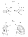
- a secondary reflector 40 connected to a waveguide 41 is shown in perspective.
- the figure 4a is a partial section.
- the secondary reflector 40 comprises a bulge, forming a horn 42 having a continuous profile as described by the aforementioned equation, placed at its smaller diameter end cooperating with the waveguide 41.
- the figure 5 is a comparison of the width of the beam emerging from a waveguide of the prior art and that of the horn having a profile as described by the equation previously mentioned placed at the end of smaller diameter of the secondary reflector.
- the amplitude of the signal S is given for a frequency of 7.8 GHz in the vertical plane (curves 50 and 51 ) and in the horizontal plane (curves 52 and 53 ) as a function of the opening angle ⁇ of the waveguide. wave (curves 51 and 53) or the horn at its end of larger diameter (curves 50 and 52 ) respectively.
- an antenna has a horn having a profile as described by the aforementioned equation, its diagram is more directive, with reduced overflow losses.
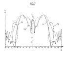
- FIG. 7 represents the radiation pattern of the secondary reflector respectively in the horizontal plane (curve 70 ) and in the vertical plane (curve 71 ). It can be seen, for an opening angle ⁇ around -120 ° and + 120 ° by relative to the axis of revolution WW 'of the reflector, areas 72 and 73 respectively in which the overflow losses are significantly improved over the antecuric art.
Landscapes
- Aerials With Secondary Devices (AREA)
- Waveguide Aerials (AREA)
Description
- La présente invention se rapporte aux antennes radiofréquences (RF) à double réflecteur. Ces antennes comportent un réflecteur primaire concave de grand diamètre et un réflecteur secondaire (« sub-reflector » en anglais) convexe de diamètre moindre situé à proximité du foyer du réflecteur primaire. Ces antennes fonctionnent indifféremment en mode transmetteur ou en mode récepteur, correspondant à deux sens opposés de propagation des ondes RF. Dans ce qui suit, la description est donnée soit en mode émission, soit en mode réception de l'antenne, selon ce qui permet de mieux illustrer les phénomènes dêcrits. Il faut noter que tous les raisonnements s'appliquent aux antennes aussi bien en réception qu'en émission.
- Les antennes à double réflecteur, notamment celles dites de type Cassegrain, sont utilisées pour réaliser des systèmes compacts. Les doubles réflecteurs comportent un réflecteur primaire concave, habituellement parabolique, ainsi qu'un réflecteur secondaire convexe de diamètre inférieur qui est placé au voisinage du foyer, sur le même axe de révolution que le réflecteur primaire. Le réflecteur primaire est percé à son sommet et un guide d'onde est inséré selon son axe. L'extrémité du guide d'onde fait face au réflecteur secondaire. En mode émission, les ondes RF transmises par le guide d'onde sont réfléchies par le réflecteur secondaire vers le réflecteur primaire.
- Le réflecteur secondaire doit être maintenu au voisinage du foyer du réflecteur primaire. Un des moyens possibles est de fixer le réflecteur secondaire à l'extrémité du guide d'onde, lui servant alors de support mécanique. Dans ce cas, le réflecteur secondaire comporte habituellement un corps diélectrique (fréquemment en plastique) sensiblement conique et transparent aux ondes RF. La surface externe de forme générale sensiblement conique du réflecteur secondaire fait face au réflecteur primaire. La surface interne convexe du réflecteur secondaire est revêtue d'un traitement permettant de réfléchir les ondes RF en dîrection du réflecteur primaire en traversant le corps diélectrique. Ce revëtement est le plus souvent en métal De multiples réflexions des ondes RF surviennent entre l'extrémité du guide d'onde et le réflecteur primaire, en impliquant le réflecteur secondaire.
- De manière à réduire ces réflexions, on a proposé d'introduire des perturbations locales, sous forme de reliefs, sur la surface externe du réflecteur secondaire faisant face au réflecteur primaire. Cependant ces reliefs ont un effet moindre sur les pertes par débordement (« spillover » en anglais).
- En mode émission de l'antenne, par exemple, les pertes par débordement, exprimées en dB, correspondent à l'énergie réfléchie par le réflecteur secondaire en direction du réflecteur primaire, et dont le trajet se termine au-delà du diamètre externe du réflecteur primaire. Ces pertes conduisent à une pollution de l'environnement par les ondes RF. Ces pertes par débordement doivent être limitées à des niveaux définis par des normes.
- Une première solution proposée est d'attacher à la périphérie du réflecteur primaire une jupe qui a la forme d'un cylindre, de diamètre voisin de celui du réflecteur primaire et de hauteur convenable, revêtu intérieurement d'une couche absorbant le rayonnement RF. Outre l'encombrement qui en résulte, cette solution connue présente l'inconvénient aujourd'hui gênant du coût du matériau de la jupe, ainsi que du coût d'assemblage de cette jupe sur le réflecteur primaire.
- Une autre solution consiste à proposer un réflecteur secondaire dont la surface externe présente un profil selon une courbe particulière. Toutefois cette solution ne permet une faible valeur de perte par débordement qu'à condition que le réflecteur secondaire ait une taille importante. En outre les pertes par réflexion ne sont réduites que pour une étroite bande de fréquence. En effet le guide d'onde produit un large faisceau de radiation avec un gain faible. Afin de réduire les pertes par débordement, le réflecteur secondaire doit donc avoir un large diamètre ou bien être placé très près du guide d'onde. Toutefois dans ce dernier cas, les performances relatives à la perte par réflexion sont affectées.
- Le document
US-6,724,349 propose de munir l'intérieur du guide d'onde de sections transversales de diamètre différent et de ménager sur la surface convexe du réflecteur secondaire des faces perpendiculaires à son axe. - La présente invention a pour but de proposer un réflecteur secondaire d'antenne à double réflecteur dont les pertes par débordement sont notablement réduites, sans présenter les inconvénients de l'art antérieur notamment en termes de dimensions et de coût.
- Les pertes par débordement pour le mode émission d'une antenne RF correspondent à des valeurs de l'angle d'éclairement (mesuré par rapport à l'axe de révolution du réflecteur secondaire) du réflecteur primaire par le réflecteur secondaire pour lesquels les ondes RF issues du guide d'onde sont réfléchies par le réflecteur secondaire dans une direction qui est en dehors du périmétre du réflecteur primaire.
- L'objet de la présente invention est un réflecteur secondaire d'antenne à double réflecteur selon la revendication 1.
- De préférence la surface externe du cornet présente un profil défini par la relation suivante :

dans laquelle - A est une constante numérique,
- aw est le premier rayon de la première extrémité du réflecteur secondaire,
- po est le deuxième rayon de la deuxième extrémité du réflecteur secondaire.
- L est la hauteur totale du réflecteur secondaire,
- z est la hauteur considérée du réflecteur secondaire, et
- p(z) est le rayon d'une section placée à la hauteur z du réflecteur secondaire.
- Selon une première variante de la constante A est égale à zéro (A = 0). Dans ce cas, la surface externe du cornet présente un profil sensiblement linéaire et le cornet a sensiblement la forme d'un cône tronqué.
- Selon une seconde variante de réalisation, la constante A est différente de zéro (A ≠ 0). Dans ce cas, la surface externe du cornet présente un profil continu de forme particulière.
- Avec un tel profil, le cornet a une meilleure efficacité, une polarisation croisée moins élevée, des lobes latéraux ayant un niveau plus faible et une bande de fréquence de largeur accrue.
- Selon une autre variante, la surface externe du cornet est métallisée. Elle peut être par exemple recouverte d'un métal réfléchissant, comme l'argent.
- L'invention propose aussi une antenne à double réflecteur comportant un réflecteur secondaire tel que précédemment décrit.
- L'invention a comme avantage de réduire notablement les pertes par débordement et de présenter de faibles pertes par réflexion.
- D'autres caractéristiques et avantages de la présente invention apparaîtront à la lecture de la description qui suit d'un mode de réalisation, donné bien entendu à titre illustratif et non limitatif, et dans le dessin annexé sur lequel
- la
figure 1 montre une coupe schématique d'un mode de réalisation d'un réflecteur secondaire selon l'invention. - la
figure 2 représente en coupe axiale schématique d'un réflecteur secondaire selon le mode de réalisation préféré de l'invention. - la
figure 3 est une vue en perspective coupée du réflecteur de lafigure 2 , - la
figure 4 montre en perspective le réflecteur de lafigure 2 . - la
figure 5 est une comparaison de la largeur du faisceau sortant d'un guide d'onde de l'art antérieur et celui sortant du cornet du réflecteur de lafigure 2 , le ? S en dB est donné en ordonnée, et en abscisse l'angle θ mesuré par rapport à l'axe de W-W' du réflecteur secondaire en degrès, - la
figure 6 montre la perte par réflexion du réflecteur de lafigure 2 , la perte par réflexion R en dB est donné en ordonnée, et en abscisse la fréquence v en GHz, - la
figure 7 reprèsente le diagramme de radiation du réflecteur de lafigure 2 , le gain G en dB est donné en ordonnée, et en abscisse l'angle θ en degrés. - Dans le mode de réalisation de l'invention illustré sur la
figure 1 , on a représenté en coupe axiale un réflecteur secondaire 1 d'une antenne à double réflecteur relié à un guide d'onde 2. Le guide d'onde 2 est ici un tube creux métallique, par exemple en aluminium. Son diamètre, d'environ λg/2,5 où λg est la longueur d'onde du signal RF guidé, est choisi de manière à permettre la propagation du mode TE11 seulement, avant l'apparition de modes supèrieurs. Le réflecteur secondaire 1 comporte un corps diélectrique 3 dont l'extrémité 4 de moindre diamètre est reliée au guide d'onde 2. Le corps diélectrique 3 du réflecteur secondaire 1 est par exemple en un matériau diélectrique comme du plastique. L'extrémité opposée 5 du corps diélectrique 3 est creusée pour former une surface interne 6 concave réfléchissante pour le signal RF. La surface interne 6 du réflecteur secondaire 1 est par exemple une surface de révolution décrite par une équation polynomiale autour d'un axe de révolution W-W' La surface interne 6 peut être recouverte d'un métal réfléchissant, comme l'argent. La surface externe 7 du réflecteur secondaire 1 est la surface placée en regard du réflecteur primaire. La surface externe 7 est une surface de révolution autour de l'axe de révolution W-W". - L'extrémité 4 du corps diélectrique 3 du réflecteur secondaire 1 est munie extérieurement d'un renflement, ici en forme de cône tronqué, formant un cornet 8 (« horn » en anglais) dont la surface externe 9 présente un profil continu. La surface extérieure 9 du cornet 8 est lisse et métallisée pour être réfléchissante. La jonction 10 du rèflecteur secondaire 1 et du guide d'onde 2 est située à l'extrémité de moindre diamètre du cornet 8. Une partie du matériau diélectrique du corps diélectrique 3 se prolonge pour pénétrer à l'intérieur du guide d'onde 2, afin d'assurer le maintien mécanique et la transition radio-électrique entre le guide d'onde 2 et le réflecteur secondaire 1.
- On considérera maintenant la
figure 2 qui illustre un mode de réalisation avantageux d'un réflecteur secondaire 20, Bien qu'un cornet de forme sensiblement conique permette de résoudre le problème, de meilleurs résultats peuvent être obtenus avec un cornet 21 dont la surface externe 22 possède un profil dèfini par la relation :
permettant des transitions douces entre un guide d'onde et la surface interne réfléchissante 23 du réflecteur secondaire 20, - Les
figures 3a et 3b montre la comparaison entre un cornet 30 en forme de cône tronqué (fig.3a ) et un cornet 31 ayant une surface externe à profil défini par la relation suivante (fig. 3b ) :
dans laquelle - A est une constante numérique,
- aw est le premier rayon de la première extrémité du réflecteur secondaire,
- ρo est le deuxième rayon de la deuxième extrémité du réflecteur secondaire,
- L est la hauteur totale du réflecteur secondaire,
- z est la hauteur considérée du réflecteur secondaire, et
- ρ(z) est le rayon d'une section placée à la hauteur z du réflecteur secondaire.
- Le cornet 31 avec un tel profil a une meilleure efficacité, une polarisation croisée moins élevée, des lobes latéraux ayant un niveau plus faible et une bande de fréquence de largeur accrue.
- Sur les
figures 4a et 4b , un réflecteur secondaire 40 relié à un guide d'onde 41 est représenté en perspective. Lafigure 4a est une coupe partielle. Le réflecteur secondaire 40 comporte un renflement, formant un cornet 42 ayant un profil continu tel que décrit par l'équation précédemment mentionnée, placé à son extrémité de moindre diamètre coopérant avec le guide d'onde 41. - La
figure 5 est une comparaison de la largeur du faisceau sortant d'un guide d'onde de l'art antérieur et celui sortant du cornet ayant un profil tel que décrit par l'équation précédemment mention placé à l'extrémité de moindre diamètre du réflecteur secondaire. L'amplitude du signal S est donné pour une fréquence de 7,8 GHz dans le plan vertical (courbes 50 et 51) et dans le plan horizontal (courbes 52 et 53) en fonction de l'angle d'ouverture θ du guide d'onde (courbes 51 et 53) ou du cornet à son extrémité de plus grand diamètre (courbes 50 et 52) respectivement. Lorsqu'une antenne comporte un cornet ayant un profil tel que décrit par l'équation précédemment mentionnée, son diagramme est plus directif, avec des pertes par débordement réduites. - On voit sur la
figure 6 la faible perte 60 par réflexion R du réflecteur secondaire en fonction de la fréquence ν du signal PF émis / transmis. - La ligure 7 représente le diagramme de radiation du réflecteur secondaire respectivement dans le plan horizontal (courbe 70) et dans le plan vertical (courbe 71), On voit, pour un angle d'ouverture ρ autour de -120° et +120° par rapport à l'axe de révolution W-W' du réflecteur, des zones 72 et 73 respectivement dans lesquelles les pertes par débordement sont nettement améliorées par rapport à l'art antércur.
Claims (6)
- Réflecteur secondaire (1) d'antenne à double réflecteur comprenant :- une première extrémité (4), ayant un premier diamètre,- une seconde extrémité (5) ayant un second diamètre plus grand que le premier diamètre,- une surface interne (6) convexe réfléchissante placée à la seconde extrémité (5) ayant un axe de révolution (w,w'),- une surface externe (7), de même axe de révolution que la surface interne (6), reliant la première extrémité (4) à la deuxième extrémité (5),- un corps diélectrique (3) s'étendant entre la première et la seconde extrémité (4, 5) et limité par la surface interne (6) et la surface externe (7),
caractérisé en ce que le corps diélectrique (3) présente au niveau de la première extrémité (4) un renflement formant un cornet (8) ayant une surface externe (9) qui présente un profil continu, dont l'extrémité de diamètre moindre est adaptée pour le couplage à l'extrémité d'un guide d'onde (2) cylindrique et dont la surface externe (9) est réfléchissante. - Réflecteur secondaire (1) selon la revendication 1, dans lequel le cornet (8) a sensiblement la forme d'un cône tronqué.
- Réflecteur secondaire (1) selon la revendication 1, dans lequel le profil de la
surface externe (9) du cornet (8) est défini par la relation:
dans laquelleA est une constante numérique,aw est le premier rayon de la première extrémité du réflecteur secondaire,ρ0 est le deuxième rayon de la deuxième extrémité du réflecteur secondaire,L est la hauteur totale du réflecteur secondaire,z est la hauteur considérée du réflecteur secondaire, etp(z) est le rayon d'une section placée à la hauteur z du réflecteur secondaire. - Réflecteur secondaire (1) selon la revendication 3, dans lequel la constante A est différente de zéro.
- Réflecteur secondaire (1) selon l'une des revendications précédentes, dans lequel la surface externe (9) du cornet (8) est métallisée.
- Antenne à double réflecteur comportant un réflecteur secondaire (1) selon l'une des revendications précédentes,
Applications Claiming Priority (1)
| Application Number | Priority Date | Filing Date | Title |
|---|---|---|---|
| FR0953694A FR2946466B1 (fr) | 2009-06-04 | 2009-06-04 | Reflecteur secondaire pour une antenne a double reflecteur |
Publications (3)
| Publication Number | Publication Date |
|---|---|
| EP2264832A2 EP2264832A2 (fr) | 2010-12-22 |
| EP2264832A3 EP2264832A3 (fr) | 2011-01-19 |
| EP2264832B1 true EP2264832B1 (fr) | 2015-08-19 |
Family
ID=41327325
Family Applications (1)
| Application Number | Title | Priority Date | Filing Date |
|---|---|---|---|
| EP10164928.3A Active EP2264832B1 (fr) | 2009-06-04 | 2010-06-04 | Réflecteur secondaire pour une antenne à double réflecteur |
Country Status (2)
| Country | Link |
|---|---|
| EP (1) | EP2264832B1 (fr) |
| FR (1) | FR2946466B1 (fr) |
Families Citing this family (147)
| Publication number | Priority date | Publication date | Assignee | Title |
|---|---|---|---|---|
| US10009065B2 (en) | 2012-12-05 | 2018-06-26 | At&T Intellectual Property I, L.P. | Backhaul link for distributed antenna system |
| US9113347B2 (en) | 2012-12-05 | 2015-08-18 | At&T Intellectual Property I, Lp | Backhaul link for distributed antenna system |
| US9525524B2 (en) | 2013-05-31 | 2016-12-20 | At&T Intellectual Property I, L.P. | Remote distributed antenna system |
| US9999038B2 (en) | 2013-05-31 | 2018-06-12 | At&T Intellectual Property I, L.P. | Remote distributed antenna system |
| US8897697B1 (en) | 2013-11-06 | 2014-11-25 | At&T Intellectual Property I, Lp | Millimeter-wave surface-wave communications |
| US9692101B2 (en) | 2014-08-26 | 2017-06-27 | At&T Intellectual Property I, L.P. | Guided wave couplers for coupling electromagnetic waves between a waveguide surface and a surface of a wire |
| US9768833B2 (en) | 2014-09-15 | 2017-09-19 | At&T Intellectual Property I, L.P. | Method and apparatus for sensing a condition in a transmission medium of electromagnetic waves |
| US10063280B2 (en) | 2014-09-17 | 2018-08-28 | At&T Intellectual Property I, L.P. | Monitoring and mitigating conditions in a communication network |
| US9615269B2 (en) | 2014-10-02 | 2017-04-04 | At&T Intellectual Property I, L.P. | Method and apparatus that provides fault tolerance in a communication network |
| US9685992B2 (en) | 2014-10-03 | 2017-06-20 | At&T Intellectual Property I, L.P. | Circuit panel network and methods thereof |
| US9503189B2 (en) | 2014-10-10 | 2016-11-22 | At&T Intellectual Property I, L.P. | Method and apparatus for arranging communication sessions in a communication system |
| US9973299B2 (en) | 2014-10-14 | 2018-05-15 | At&T Intellectual Property I, L.P. | Method and apparatus for adjusting a mode of communication in a communication network |
| US9762289B2 (en) | 2014-10-14 | 2017-09-12 | At&T Intellectual Property I, L.P. | Method and apparatus for transmitting or receiving signals in a transportation system |
| US9769020B2 (en) | 2014-10-21 | 2017-09-19 | At&T Intellectual Property I, L.P. | Method and apparatus for responding to events affecting communications in a communication network |
| US9653770B2 (en) | 2014-10-21 | 2017-05-16 | At&T Intellectual Property I, L.P. | Guided wave coupler, coupling module and methods for use therewith |
| US9577306B2 (en) | 2014-10-21 | 2017-02-21 | At&T Intellectual Property I, L.P. | Guided-wave transmission device and methods for use therewith |
| US9627768B2 (en) | 2014-10-21 | 2017-04-18 | At&T Intellectual Property I, L.P. | Guided-wave transmission device with non-fundamental mode propagation and methods for use therewith |
| US9312919B1 (en) | 2014-10-21 | 2016-04-12 | At&T Intellectual Property I, Lp | Transmission device with impairment compensation and methods for use therewith |
| US9520945B2 (en) | 2014-10-21 | 2016-12-13 | At&T Intellectual Property I, L.P. | Apparatus for providing communication services and methods thereof |
| US9780834B2 (en) | 2014-10-21 | 2017-10-03 | At&T Intellectual Property I, L.P. | Method and apparatus for transmitting electromagnetic waves |
| US9544006B2 (en) | 2014-11-20 | 2017-01-10 | At&T Intellectual Property I, L.P. | Transmission device with mode division multiplexing and methods for use therewith |
| US10243784B2 (en) | 2014-11-20 | 2019-03-26 | At&T Intellectual Property I, L.P. | System for generating topology information and methods thereof |
| US10340573B2 (en) | 2016-10-26 | 2019-07-02 | At&T Intellectual Property I, L.P. | Launcher with cylindrical coupling device and methods for use therewith |
| US9997819B2 (en) | 2015-06-09 | 2018-06-12 | At&T Intellectual Property I, L.P. | Transmission medium and method for facilitating propagation of electromagnetic waves via a core |
| US10009067B2 (en) | 2014-12-04 | 2018-06-26 | At&T Intellectual Property I, L.P. | Method and apparatus for configuring a communication interface |
| US9800327B2 (en) | 2014-11-20 | 2017-10-24 | At&T Intellectual Property I, L.P. | Apparatus for controlling operations of a communication device and methods thereof |
| US9742462B2 (en) | 2014-12-04 | 2017-08-22 | At&T Intellectual Property I, L.P. | Transmission medium and communication interfaces and methods for use therewith |
| US9461706B1 (en) | 2015-07-31 | 2016-10-04 | At&T Intellectual Property I, Lp | Method and apparatus for exchanging communication signals |
| US9954287B2 (en) | 2014-11-20 | 2018-04-24 | At&T Intellectual Property I, L.P. | Apparatus for converting wireless signals and electromagnetic waves and methods thereof |
| US10144036B2 (en) | 2015-01-30 | 2018-12-04 | At&T Intellectual Property I, L.P. | Method and apparatus for mitigating interference affecting a propagation of electromagnetic waves guided by a transmission medium |
| US9876570B2 (en) | 2015-02-20 | 2018-01-23 | At&T Intellectual Property I, Lp | Guided-wave transmission device with non-fundamental mode propagation and methods for use therewith |
| US9749013B2 (en) | 2015-03-17 | 2017-08-29 | At&T Intellectual Property I, L.P. | Method and apparatus for reducing attenuation of electromagnetic waves guided by a transmission medium |
| US9705561B2 (en) | 2015-04-24 | 2017-07-11 | At&T Intellectual Property I, L.P. | Directional coupling device and methods for use therewith |
| US10224981B2 (en) | 2015-04-24 | 2019-03-05 | At&T Intellectual Property I, Lp | Passive electrical coupling device and methods for use therewith |
| US9793954B2 (en) | 2015-04-28 | 2017-10-17 | At&T Intellectual Property I, L.P. | Magnetic coupling device and methods for use therewith |
| US9948354B2 (en) | 2015-04-28 | 2018-04-17 | At&T Intellectual Property I, L.P. | Magnetic coupling device with reflective plate and methods for use therewith |
| US9748626B2 (en) | 2015-05-14 | 2017-08-29 | At&T Intellectual Property I, L.P. | Plurality of cables having different cross-sectional shapes which are bundled together to form a transmission medium |
| US9871282B2 (en) | 2015-05-14 | 2018-01-16 | At&T Intellectual Property I, L.P. | At least one transmission medium having a dielectric surface that is covered at least in part by a second dielectric |
| US9490869B1 (en) | 2015-05-14 | 2016-11-08 | At&T Intellectual Property I, L.P. | Transmission medium having multiple cores and methods for use therewith |
| US10650940B2 (en) | 2015-05-15 | 2020-05-12 | At&T Intellectual Property I, L.P. | Transmission medium having a conductive material and methods for use therewith |
| US9917341B2 (en) | 2015-05-27 | 2018-03-13 | At&T Intellectual Property I, L.P. | Apparatus and method for launching electromagnetic waves and for modifying radial dimensions of the propagating electromagnetic waves |
| US10103801B2 (en) | 2015-06-03 | 2018-10-16 | At&T Intellectual Property I, L.P. | Host node device and methods for use therewith |
| US10812174B2 (en) | 2015-06-03 | 2020-10-20 | At&T Intellectual Property I, L.P. | Client node device and methods for use therewith |
| US9912381B2 (en) | 2015-06-03 | 2018-03-06 | At&T Intellectual Property I, Lp | Network termination and methods for use therewith |
| US9866309B2 (en) | 2015-06-03 | 2018-01-09 | At&T Intellectual Property I, Lp | Host node device and methods for use therewith |
| US9913139B2 (en) | 2015-06-09 | 2018-03-06 | At&T Intellectual Property I, L.P. | Signal fingerprinting for authentication of communicating devices |
| US9608692B2 (en) | 2015-06-11 | 2017-03-28 | At&T Intellectual Property I, L.P. | Repeater and methods for use therewith |
| US10142086B2 (en) | 2015-06-11 | 2018-11-27 | At&T Intellectual Property I, L.P. | Repeater and methods for use therewith |
| US9820146B2 (en) | 2015-06-12 | 2017-11-14 | At&T Intellectual Property I, L.P. | Method and apparatus for authentication and identity management of communicating devices |
| US9667317B2 (en) | 2015-06-15 | 2017-05-30 | At&T Intellectual Property I, L.P. | Method and apparatus for providing security using network traffic adjustments |
| US9640850B2 (en) | 2015-06-25 | 2017-05-02 | At&T Intellectual Property I, L.P. | Methods and apparatus for inducing a non-fundamental wave mode on a transmission medium |
| US9509415B1 (en) | 2015-06-25 | 2016-11-29 | At&T Intellectual Property I, L.P. | Methods and apparatus for inducing a fundamental wave mode on a transmission medium |
| US9865911B2 (en) | 2015-06-25 | 2018-01-09 | At&T Intellectual Property I, L.P. | Waveguide system for slot radiating first electromagnetic waves that are combined into a non-fundamental wave mode second electromagnetic wave on a transmission medium |
| US9853342B2 (en) | 2015-07-14 | 2017-12-26 | At&T Intellectual Property I, L.P. | Dielectric transmission medium connector and methods for use therewith |
| US9628116B2 (en) | 2015-07-14 | 2017-04-18 | At&T Intellectual Property I, L.P. | Apparatus and methods for transmitting wireless signals |
| US10033108B2 (en) | 2015-07-14 | 2018-07-24 | At&T Intellectual Property I, L.P. | Apparatus and methods for generating an electromagnetic wave having a wave mode that mitigates interference |
| US9882257B2 (en) | 2015-07-14 | 2018-01-30 | At&T Intellectual Property I, L.P. | Method and apparatus for launching a wave mode that mitigates interference |
| US10044409B2 (en) | 2015-07-14 | 2018-08-07 | At&T Intellectual Property I, L.P. | Transmission medium and methods for use therewith |
| US10148016B2 (en) | 2015-07-14 | 2018-12-04 | At&T Intellectual Property I, L.P. | Apparatus and methods for communicating utilizing an antenna array |
| US10320586B2 (en) | 2015-07-14 | 2019-06-11 | At&T Intellectual Property I, L.P. | Apparatus and methods for generating non-interfering electromagnetic waves on an insulated transmission medium |
| US10033107B2 (en) | 2015-07-14 | 2018-07-24 | At&T Intellectual Property I, L.P. | Method and apparatus for coupling an antenna to a device |
| US9847566B2 (en) | 2015-07-14 | 2017-12-19 | At&T Intellectual Property I, L.P. | Method and apparatus for adjusting a field of a signal to mitigate interference |
| US9722318B2 (en) | 2015-07-14 | 2017-08-01 | At&T Intellectual Property I, L.P. | Method and apparatus for coupling an antenna to a device |
| US10170840B2 (en) | 2015-07-14 | 2019-01-01 | At&T Intellectual Property I, L.P. | Apparatus and methods for sending or receiving electromagnetic signals |
| US10205655B2 (en) | 2015-07-14 | 2019-02-12 | At&T Intellectual Property I, L.P. | Apparatus and methods for communicating utilizing an antenna array and multiple communication paths |
| US10341142B2 (en) | 2015-07-14 | 2019-07-02 | At&T Intellectual Property I, L.P. | Apparatus and methods for generating non-interfering electromagnetic waves on an uninsulated conductor |
| US9793951B2 (en) | 2015-07-15 | 2017-10-17 | At&T Intellectual Property I, L.P. | Method and apparatus for launching a wave mode that mitigates interference |
| US10090606B2 (en) | 2015-07-15 | 2018-10-02 | At&T Intellectual Property I, L.P. | Antenna system with dielectric array and methods for use therewith |
| US9608740B2 (en) | 2015-07-15 | 2017-03-28 | At&T Intellectual Property I, L.P. | Method and apparatus for launching a wave mode that mitigates interference |
| US9912027B2 (en) | 2015-07-23 | 2018-03-06 | At&T Intellectual Property I, L.P. | Method and apparatus for exchanging communication signals |
| US9749053B2 (en) | 2015-07-23 | 2017-08-29 | At&T Intellectual Property I, L.P. | Node device, repeater and methods for use therewith |
| US9948333B2 (en) | 2015-07-23 | 2018-04-17 | At&T Intellectual Property I, L.P. | Method and apparatus for wireless communications to mitigate interference |
| US9871283B2 (en) | 2015-07-23 | 2018-01-16 | At&T Intellectual Property I, Lp | Transmission medium having a dielectric core comprised of plural members connected by a ball and socket configuration |
| US9967173B2 (en) | 2015-07-31 | 2018-05-08 | At&T Intellectual Property I, L.P. | Method and apparatus for authentication and identity management of communicating devices |
| US9735833B2 (en) | 2015-07-31 | 2017-08-15 | At&T Intellectual Property I, L.P. | Method and apparatus for communications management in a neighborhood network |
| US9904535B2 (en) | 2015-09-14 | 2018-02-27 | At&T Intellectual Property I, L.P. | Method and apparatus for distributing software |
| US10009063B2 (en) | 2015-09-16 | 2018-06-26 | At&T Intellectual Property I, L.P. | Method and apparatus for use with a radio distributed antenna system having an out-of-band reference signal |
| US10079661B2 (en) | 2015-09-16 | 2018-09-18 | At&T Intellectual Property I, L.P. | Method and apparatus for use with a radio distributed antenna system having a clock reference |
| US10136434B2 (en) | 2015-09-16 | 2018-11-20 | At&T Intellectual Property I, L.P. | Method and apparatus for use with a radio distributed antenna system having an ultra-wideband control channel |
| US9769128B2 (en) | 2015-09-28 | 2017-09-19 | At&T Intellectual Property I, L.P. | Method and apparatus for encryption of communications over a network |
| US9729197B2 (en) | 2015-10-01 | 2017-08-08 | At&T Intellectual Property I, L.P. | Method and apparatus for communicating network management traffic over a network |
| US9876264B2 (en) | 2015-10-02 | 2018-01-23 | At&T Intellectual Property I, Lp | Communication system, guided wave switch and methods for use therewith |
| US10355367B2 (en) | 2015-10-16 | 2019-07-16 | At&T Intellectual Property I, L.P. | Antenna structure for exchanging wireless signals |
| US10665942B2 (en) | 2015-10-16 | 2020-05-26 | At&T Intellectual Property I, L.P. | Method and apparatus for adjusting wireless communications |
| US9912419B1 (en) | 2016-08-24 | 2018-03-06 | At&T Intellectual Property I, L.P. | Method and apparatus for managing a fault in a distributed antenna system |
| US9860075B1 (en) | 2016-08-26 | 2018-01-02 | At&T Intellectual Property I, L.P. | Method and communication node for broadband distribution |
| US10291311B2 (en) | 2016-09-09 | 2019-05-14 | At&T Intellectual Property I, L.P. | Method and apparatus for mitigating a fault in a distributed antenna system |
| US11032819B2 (en) | 2016-09-15 | 2021-06-08 | At&T Intellectual Property I, L.P. | Method and apparatus for use with a radio distributed antenna system having a control channel reference signal |
| US10340600B2 (en) | 2016-10-18 | 2019-07-02 | At&T Intellectual Property I, L.P. | Apparatus and methods for launching guided waves via plural waveguide systems |
| US10135147B2 (en) | 2016-10-18 | 2018-11-20 | At&T Intellectual Property I, L.P. | Apparatus and methods for launching guided waves via an antenna |
| US10135146B2 (en) | 2016-10-18 | 2018-11-20 | At&T Intellectual Property I, L.P. | Apparatus and methods for launching guided waves via circuits |
| US10374316B2 (en) | 2016-10-21 | 2019-08-06 | At&T Intellectual Property I, L.P. | System and dielectric antenna with non-uniform dielectric |
| US9876605B1 (en) | 2016-10-21 | 2018-01-23 | At&T Intellectual Property I, L.P. | Launcher and coupling system to support desired guided wave mode |
| US10811767B2 (en) | 2016-10-21 | 2020-10-20 | At&T Intellectual Property I, L.P. | System and dielectric antenna with convex dielectric radome |
| US9991580B2 (en) | 2016-10-21 | 2018-06-05 | At&T Intellectual Property I, L.P. | Launcher and coupling system for guided wave mode cancellation |
| US10312567B2 (en) | 2016-10-26 | 2019-06-04 | At&T Intellectual Property I, L.P. | Launcher with planar strip antenna and methods for use therewith |
| US10291334B2 (en) | 2016-11-03 | 2019-05-14 | At&T Intellectual Property I, L.P. | System for detecting a fault in a communication system |
| US10498044B2 (en) | 2016-11-03 | 2019-12-03 | At&T Intellectual Property I, L.P. | Apparatus for configuring a surface of an antenna |
| US10224634B2 (en) | 2016-11-03 | 2019-03-05 | At&T Intellectual Property I, L.P. | Methods and apparatus for adjusting an operational characteristic of an antenna |
| US10225025B2 (en) | 2016-11-03 | 2019-03-05 | At&T Intellectual Property I, L.P. | Method and apparatus for detecting a fault in a communication system |
| US10340603B2 (en) | 2016-11-23 | 2019-07-02 | At&T Intellectual Property I, L.P. | Antenna system having shielded structural configurations for assembly |
| US10340601B2 (en) | 2016-11-23 | 2019-07-02 | At&T Intellectual Property I, L.P. | Multi-antenna system and methods for use therewith |
| US10090594B2 (en) | 2016-11-23 | 2018-10-02 | At&T Intellectual Property I, L.P. | Antenna system having structural configurations for assembly |
| US10178445B2 (en) | 2016-11-23 | 2019-01-08 | At&T Intellectual Property I, L.P. | Methods, devices, and systems for load balancing between a plurality of waveguides |
| US10535928B2 (en) | 2016-11-23 | 2020-01-14 | At&T Intellectual Property I, L.P. | Antenna system and methods for use therewith |
| US10361489B2 (en) | 2016-12-01 | 2019-07-23 | At&T Intellectual Property I, L.P. | Dielectric dish antenna system and methods for use therewith |
| US10305190B2 (en) | 2016-12-01 | 2019-05-28 | At&T Intellectual Property I, L.P. | Reflecting dielectric antenna system and methods for use therewith |
| US10694379B2 (en) | 2016-12-06 | 2020-06-23 | At&T Intellectual Property I, L.P. | Waveguide system with device-based authentication and methods for use therewith |
| US10819035B2 (en) | 2016-12-06 | 2020-10-27 | At&T Intellectual Property I, L.P. | Launcher with helical antenna and methods for use therewith |
| US9927517B1 (en) | 2016-12-06 | 2018-03-27 | At&T Intellectual Property I, L.P. | Apparatus and methods for sensing rainfall |
| US10637149B2 (en) | 2016-12-06 | 2020-04-28 | At&T Intellectual Property I, L.P. | Injection molded dielectric antenna and methods for use therewith |
| US10755542B2 (en) | 2016-12-06 | 2020-08-25 | At&T Intellectual Property I, L.P. | Method and apparatus for surveillance via guided wave communication |
| US10135145B2 (en) | 2016-12-06 | 2018-11-20 | At&T Intellectual Property I, L.P. | Apparatus and methods for generating an electromagnetic wave along a transmission medium |
| US10020844B2 (en) | 2016-12-06 | 2018-07-10 | T&T Intellectual Property I, L.P. | Method and apparatus for broadcast communication via guided waves |
| US10326494B2 (en) | 2016-12-06 | 2019-06-18 | At&T Intellectual Property I, L.P. | Apparatus for measurement de-embedding and methods for use therewith |
| US10439675B2 (en) | 2016-12-06 | 2019-10-08 | At&T Intellectual Property I, L.P. | Method and apparatus for repeating guided wave communication signals |
| US10727599B2 (en) | 2016-12-06 | 2020-07-28 | At&T Intellectual Property I, L.P. | Launcher with slot antenna and methods for use therewith |
| US10382976B2 (en) | 2016-12-06 | 2019-08-13 | At&T Intellectual Property I, L.P. | Method and apparatus for managing wireless communications based on communication paths and network device positions |
| US10139820B2 (en) | 2016-12-07 | 2018-11-27 | At&T Intellectual Property I, L.P. | Method and apparatus for deploying equipment of a communication system |
| US10168695B2 (en) | 2016-12-07 | 2019-01-01 | At&T Intellectual Property I, L.P. | Method and apparatus for controlling an unmanned aircraft |
| US10359749B2 (en) | 2016-12-07 | 2019-07-23 | At&T Intellectual Property I, L.P. | Method and apparatus for utilities management via guided wave communication |
| US10446936B2 (en) | 2016-12-07 | 2019-10-15 | At&T Intellectual Property I, L.P. | Multi-feed dielectric antenna system and methods for use therewith |
| US10547348B2 (en) | 2016-12-07 | 2020-01-28 | At&T Intellectual Property I, L.P. | Method and apparatus for switching transmission mediums in a communication system |
| US10389029B2 (en) | 2016-12-07 | 2019-08-20 | At&T Intellectual Property I, L.P. | Multi-feed dielectric antenna system with core selection and methods for use therewith |
| US10243270B2 (en) | 2016-12-07 | 2019-03-26 | At&T Intellectual Property I, L.P. | Beam adaptive multi-feed dielectric antenna system and methods for use therewith |
| US9893795B1 (en) | 2016-12-07 | 2018-02-13 | At&T Intellectual Property I, Lp | Method and repeater for broadband distribution |
| US10027397B2 (en) | 2016-12-07 | 2018-07-17 | At&T Intellectual Property I, L.P. | Distributed antenna system and methods for use therewith |
| US10103422B2 (en) | 2016-12-08 | 2018-10-16 | At&T Intellectual Property I, L.P. | Method and apparatus for mounting network devices |
| US10916969B2 (en) | 2016-12-08 | 2021-02-09 | At&T Intellectual Property I, L.P. | Method and apparatus for providing power using an inductive coupling |
| US9911020B1 (en) | 2016-12-08 | 2018-03-06 | At&T Intellectual Property I, L.P. | Method and apparatus for tracking via a radio frequency identification device |
| US10530505B2 (en) | 2016-12-08 | 2020-01-07 | At&T Intellectual Property I, L.P. | Apparatus and methods for launching electromagnetic waves along a transmission medium |
| US10777873B2 (en) | 2016-12-08 | 2020-09-15 | At&T Intellectual Property I, L.P. | Method and apparatus for mounting network devices |
| US10326689B2 (en) | 2016-12-08 | 2019-06-18 | At&T Intellectual Property I, L.P. | Method and system for providing alternative communication paths |
| US10601494B2 (en) | 2016-12-08 | 2020-03-24 | At&T Intellectual Property I, L.P. | Dual-band communication device and method for use therewith |
| US10411356B2 (en) | 2016-12-08 | 2019-09-10 | At&T Intellectual Property I, L.P. | Apparatus and methods for selectively targeting communication devices with an antenna array |
| US10389037B2 (en) | 2016-12-08 | 2019-08-20 | At&T Intellectual Property I, L.P. | Apparatus and methods for selecting sections of an antenna array and use therewith |
| US10938108B2 (en) | 2016-12-08 | 2021-03-02 | At&T Intellectual Property I, L.P. | Frequency selective multi-feed dielectric antenna system and methods for use therewith |
| US9998870B1 (en) | 2016-12-08 | 2018-06-12 | At&T Intellectual Property I, L.P. | Method and apparatus for proximity sensing |
| US10069535B2 (en) | 2016-12-08 | 2018-09-04 | At&T Intellectual Property I, L.P. | Apparatus and methods for launching electromagnetic waves having a certain electric field structure |
| US10340983B2 (en) | 2016-12-09 | 2019-07-02 | At&T Intellectual Property I, L.P. | Method and apparatus for surveying remote sites via guided wave communications |
| US10264586B2 (en) | 2016-12-09 | 2019-04-16 | At&T Mobility Ii Llc | Cloud-based packet controller and methods for use therewith |
| US9838896B1 (en) | 2016-12-09 | 2017-12-05 | At&T Intellectual Property I, L.P. | Method and apparatus for assessing network coverage |
| US9973940B1 (en) | 2017-02-27 | 2018-05-15 | At&T Intellectual Property I, L.P. | Apparatus and methods for dynamic impedance matching of a guided wave launcher |
| US10298293B2 (en) | 2017-03-13 | 2019-05-21 | At&T Intellectual Property I, L.P. | Apparatus of communication utilizing wireless network devices |
| CN107579353B (zh) * | 2017-08-25 | 2020-10-09 | 西安电子科技大学 | 基于超表面的高定向性柱状凸面共形反射面天线 |
| CN110571531B (zh) * | 2019-09-27 | 2021-07-30 | 中国电子科技集团公司第三十八研究所 | 一种基于抛物柱面反射阵的多波束相控阵天线 |
| US11791562B2 (en) * | 2021-02-04 | 2023-10-17 | Orbit Communication Systems Ltd. | Ring focus antenna system with an ultra-wide bandwidth |
Family Cites Families (2)
| Publication number | Priority date | Publication date | Assignee | Title |
|---|---|---|---|---|
| US6724349B1 (en) * | 2002-11-12 | 2004-04-20 | L-3 Communications Corporation | Splashplate antenna system with improved waveguide and splashplate (sub-reflector) designs |
| JP4919423B2 (ja) * | 2007-07-06 | 2012-04-18 | 日本無線株式会社 | アンテナ給電部 |
-
2009
- 2009-06-04 FR FR0953694A patent/FR2946466B1/fr not_active Expired - Fee Related
-
2010
- 2010-06-04 EP EP10164928.3A patent/EP2264832B1/fr active Active
Also Published As
| Publication number | Publication date |
|---|---|
| FR2946466B1 (fr) | 2012-03-30 |
| EP2264832A3 (fr) | 2011-01-19 |
| FR2946466A1 (fr) | 2010-12-10 |
| EP2264832A2 (fr) | 2010-12-22 |
Similar Documents
| Publication | Publication Date | Title |
|---|---|---|
| EP2264832B1 (fr) | Réflecteur secondaire pour une antenne à double réflecteur | |
| EP2081258B1 (fr) | Réflecteur secondaire d'une antenne à double réflecteur | |
| EP2804259B1 (fr) | Radôme pour une antenne à réflecteur concave | |
| FR2986376A1 (fr) | Reflecteur secondaire d'antenne a double reflecteur | |
| EP0274074B1 (fr) | Source d'illumination pour antenne de télécommunications | |
| EP3109941B1 (fr) | Antenne micro onde à double réflecteur | |
| EP1445829A1 (fr) | Reflecteur secondaire pour antenne hyperfrequence de type cassegrain | |
| EP2416449A1 (fr) | Antenne à réflecteur parabolique | |
| EP1489688B1 (fr) | Alimentation pour une antenne a reflecteur | |
| EP2658032B1 (fr) | Cornet d'antenne à grille corruguée | |
| WO2008037887A2 (fr) | Antenne a materiau bip (bande interdite photonique) systeme | |
| EP0031275B1 (fr) | Fenêtre hyperfréquence et guide d'onde comportant une telle fenêtre | |
| FR2954858A1 (fr) | Antenne rayonnant un signal dans une direction de l'espace dependant de la frequence de ce signal | |
| EP3721501B1 (fr) | Composant micro-ondes et procédé de fabrication associé | |
| EP2264833B1 (fr) | Réflecteur secondaire d'antenne parabolique | |
| EP3968465B1 (fr) | Antenne à couverture améliorée sur un domaine de fréquence élargi | |
| EP4616480A1 (fr) | Antenne striée a double polarisation | |
| EP3155690B1 (fr) | Antenne plate de telecommunication par satellite | |
| FR2594260A1 (fr) | Source primaire hyperfrequence pour antenne a balayage conique et antenne l'incorporant. | |
| EP3264531A1 (fr) | Antenne micro onde à double réflecteur | |
| FR2968848A1 (fr) | Antenne a reflecteur parabolique | |
| EP3155689B1 (fr) | Antenne plate de telecommunication par satellite | |
| EP1066741B1 (fr) | Structure de circuits electroniques a encombrement optimise en fonction du volume disponible | |
| FR2731846A1 (fr) | Paroi pour radomes et radomes ainsi obtenus | |
| FR2909225A1 (fr) | Dispositif d'alimentation d'une antenne a reflecteur |
Legal Events
| Date | Code | Title | Description |
|---|---|---|---|
| PUAI | Public reference made under article 153(3) epc to a published international application that has entered the european phase |
Free format text: ORIGINAL CODE: 0009012 |
|
| PUAL | Search report despatched |
Free format text: ORIGINAL CODE: 0009013 |
|
| AK | Designated contracting states |
Kind code of ref document: A2 Designated state(s): AL AT BE BG CH CY CZ DE DK EE ES FI FR GB GR HR HU IE IS IT LI LT LU LV MC MK MT NL NO PL PT RO SE SI SK SM TR |
|
| AX | Request for extension of the european patent |
Extension state: BA ME RS |
|
| AK | Designated contracting states |
Kind code of ref document: A3 Designated state(s): AL AT BE BG CH CY CZ DE DK EE ES FI FR GB GR HR HU IE IS IT LI LT LU LV MC MK MT NL NO PL PT RO SE SI SK SM TR |
|
| AX | Request for extension of the european patent |
Extension state: BA ME RS |
|
| 17P | Request for examination filed |
Effective date: 20110719 |
|
| 17Q | First examination report despatched |
Effective date: 20120521 |
|
| 111Z | Information provided on other rights and legal means of execution |
Free format text: AL AT BE BG CH CY CZ DE DK EE ES FI FR GB GR HR HU IE IS IT LI LT LU LV MC MK MT NL NO PL PT RO SE SI SK SM TR Effective date: 20130410 |
|
| RAP1 | Party data changed (applicant data changed or rights of an application transferred) |
Owner name: ALCATEL LUCENT |
|
| D11X | Information provided on other rights and legal means of execution (deleted) | ||
| GRAP | Despatch of communication of intention to grant a patent |
Free format text: ORIGINAL CODE: EPIDOSNIGR1 |
|
| INTG | Intention to grant announced |
Effective date: 20150319 |
|
| GRAS | Grant fee paid |
Free format text: ORIGINAL CODE: EPIDOSNIGR3 |
|
| GRAA | (expected) grant |
Free format text: ORIGINAL CODE: 0009210 |
|
| AK | Designated contracting states |
Kind code of ref document: B1 Designated state(s): AL AT BE BG CH CY CZ DE DK EE ES FI FR GB GR HR HU IE IS IT LI LT LU LV MC MK MT NL NO PL PT RO SE SI SK SM TR |
|
| REG | Reference to a national code |
Ref country code: GB Ref legal event code: FG4D Free format text: NOT ENGLISH |
|
| REG | Reference to a national code |
Ref country code: CH Ref legal event code: EP |
|
| REG | Reference to a national code |
Ref country code: IE Ref legal event code: FG4D Free format text: LANGUAGE OF EP DOCUMENT: FRENCH |
|
| REG | Reference to a national code |
Ref country code: AT Ref legal event code: REF Ref document number: 744371 Country of ref document: AT Kind code of ref document: T Effective date: 20150915 |
|
| REG | Reference to a national code |
Ref country code: DE Ref legal event code: R096 Ref document number: 602010026750 Country of ref document: DE |
|
| REG | Reference to a national code |
Ref country code: AT Ref legal event code: MK05 Ref document number: 744371 Country of ref document: AT Kind code of ref document: T Effective date: 20150819 |
|
| REG | Reference to a national code |
Ref country code: LT Ref legal event code: MG4D |
|
| REG | Reference to a national code |
Ref country code: NL Ref legal event code: MP Effective date: 20150819 |
|
| PG25 | Lapsed in a contracting state [announced via postgrant information from national office to epo] |
Ref country code: LT Free format text: LAPSE BECAUSE OF FAILURE TO SUBMIT A TRANSLATION OF THE DESCRIPTION OR TO PAY THE FEE WITHIN THE PRESCRIBED TIME-LIMIT Effective date: 20150819 Ref country code: LV Free format text: LAPSE BECAUSE OF FAILURE TO SUBMIT A TRANSLATION OF THE DESCRIPTION OR TO PAY THE FEE WITHIN THE PRESCRIBED TIME-LIMIT Effective date: 20150819 Ref country code: FI Free format text: LAPSE BECAUSE OF FAILURE TO SUBMIT A TRANSLATION OF THE DESCRIPTION OR TO PAY THE FEE WITHIN THE PRESCRIBED TIME-LIMIT Effective date: 20150819 Ref country code: NO Free format text: LAPSE BECAUSE OF FAILURE TO SUBMIT A TRANSLATION OF THE DESCRIPTION OR TO PAY THE FEE WITHIN THE PRESCRIBED TIME-LIMIT Effective date: 20151119 Ref country code: GR Free format text: LAPSE BECAUSE OF FAILURE TO SUBMIT A TRANSLATION OF THE DESCRIPTION OR TO PAY THE FEE WITHIN THE PRESCRIBED TIME-LIMIT Effective date: 20151120 |
|
| PG25 | Lapsed in a contracting state [announced via postgrant information from national office to epo] |
Ref country code: PT Free format text: LAPSE BECAUSE OF FAILURE TO SUBMIT A TRANSLATION OF THE DESCRIPTION OR TO PAY THE FEE WITHIN THE PRESCRIBED TIME-LIMIT Effective date: 20151221 Ref country code: SE Free format text: LAPSE BECAUSE OF FAILURE TO SUBMIT A TRANSLATION OF THE DESCRIPTION OR TO PAY THE FEE WITHIN THE PRESCRIBED TIME-LIMIT Effective date: 20150819 Ref country code: AT Free format text: LAPSE BECAUSE OF FAILURE TO SUBMIT A TRANSLATION OF THE DESCRIPTION OR TO PAY THE FEE WITHIN THE PRESCRIBED TIME-LIMIT Effective date: 20150819 Ref country code: ES Free format text: LAPSE BECAUSE OF FAILURE TO SUBMIT A TRANSLATION OF THE DESCRIPTION OR TO PAY THE FEE WITHIN THE PRESCRIBED TIME-LIMIT Effective date: 20150819 Ref country code: PL Free format text: LAPSE BECAUSE OF FAILURE TO SUBMIT A TRANSLATION OF THE DESCRIPTION OR TO PAY THE FEE WITHIN THE PRESCRIBED TIME-LIMIT Effective date: 20150819 Ref country code: IS Free format text: LAPSE BECAUSE OF FAILURE TO SUBMIT A TRANSLATION OF THE DESCRIPTION OR TO PAY THE FEE WITHIN THE PRESCRIBED TIME-LIMIT Effective date: 20151219 |
|
| PG25 | Lapsed in a contracting state [announced via postgrant information from national office to epo] |
Ref country code: NL Free format text: LAPSE BECAUSE OF FAILURE TO SUBMIT A TRANSLATION OF THE DESCRIPTION OR TO PAY THE FEE WITHIN THE PRESCRIBED TIME-LIMIT Effective date: 20150819 |
|
| PG25 | Lapsed in a contracting state [announced via postgrant information from national office to epo] |
Ref country code: DK Free format text: LAPSE BECAUSE OF FAILURE TO SUBMIT A TRANSLATION OF THE DESCRIPTION OR TO PAY THE FEE WITHIN THE PRESCRIBED TIME-LIMIT Effective date: 20150819 Ref country code: EE Free format text: LAPSE BECAUSE OF FAILURE TO SUBMIT A TRANSLATION OF THE DESCRIPTION OR TO PAY THE FEE WITHIN THE PRESCRIBED TIME-LIMIT Effective date: 20150819 Ref country code: IT Free format text: LAPSE BECAUSE OF FAILURE TO SUBMIT A TRANSLATION OF THE DESCRIPTION OR TO PAY THE FEE WITHIN THE PRESCRIBED TIME-LIMIT Effective date: 20150819 Ref country code: CZ Free format text: LAPSE BECAUSE OF FAILURE TO SUBMIT A TRANSLATION OF THE DESCRIPTION OR TO PAY THE FEE WITHIN THE PRESCRIBED TIME-LIMIT Effective date: 20150819 Ref country code: SK Free format text: LAPSE BECAUSE OF FAILURE TO SUBMIT A TRANSLATION OF THE DESCRIPTION OR TO PAY THE FEE WITHIN THE PRESCRIBED TIME-LIMIT Effective date: 20150819 |
|
| REG | Reference to a national code |
Ref country code: DE Ref legal event code: R097 Ref document number: 602010026750 Country of ref document: DE |
|
| PG25 | Lapsed in a contracting state [announced via postgrant information from national office to epo] |
Ref country code: RO Free format text: LAPSE BECAUSE OF FAILURE TO SUBMIT A TRANSLATION OF THE DESCRIPTION OR TO PAY THE FEE WITHIN THE PRESCRIBED TIME-LIMIT Effective date: 20150819 |
|
| PLBE | No opposition filed within time limit |
Free format text: ORIGINAL CODE: 0009261 |
|
| STAA | Information on the status of an ep patent application or granted ep patent |
Free format text: STATUS: NO OPPOSITION FILED WITHIN TIME LIMIT |
|
| REG | Reference to a national code |
Ref country code: FR Ref legal event code: PLFP Year of fee payment: 7 |
|
| 26N | No opposition filed |
Effective date: 20160520 |
|
| PG25 | Lapsed in a contracting state [announced via postgrant information from national office to epo] |
Ref country code: SI Free format text: LAPSE BECAUSE OF FAILURE TO SUBMIT A TRANSLATION OF THE DESCRIPTION OR TO PAY THE FEE WITHIN THE PRESCRIBED TIME-LIMIT Effective date: 20150819 |
|
| PG25 | Lapsed in a contracting state [announced via postgrant information from national office to epo] |
Ref country code: BE Free format text: LAPSE BECAUSE OF NON-PAYMENT OF DUE FEES Effective date: 20160630 |
|
| PG25 | Lapsed in a contracting state [announced via postgrant information from national office to epo] |
Ref country code: MC Free format text: LAPSE BECAUSE OF FAILURE TO SUBMIT A TRANSLATION OF THE DESCRIPTION OR TO PAY THE FEE WITHIN THE PRESCRIBED TIME-LIMIT Effective date: 20150819 |
|
| REG | Reference to a national code |
Ref country code: CH Ref legal event code: PL |
|
| REG | Reference to a national code |
Ref country code: IE Ref legal event code: MM4A |
|
| PG25 | Lapsed in a contracting state [announced via postgrant information from national office to epo] |
Ref country code: LI Free format text: LAPSE BECAUSE OF NON-PAYMENT OF DUE FEES Effective date: 20160630 Ref country code: CH Free format text: LAPSE BECAUSE OF NON-PAYMENT OF DUE FEES Effective date: 20160630 |
|
| PG25 | Lapsed in a contracting state [announced via postgrant information from national office to epo] |
Ref country code: IE Free format text: LAPSE BECAUSE OF NON-PAYMENT OF DUE FEES Effective date: 20160604 |
|
| REG | Reference to a national code |
Ref country code: FR Ref legal event code: PLFP Year of fee payment: 8 |
|
| PG25 | Lapsed in a contracting state [announced via postgrant information from national office to epo] |
Ref country code: SM Free format text: LAPSE BECAUSE OF FAILURE TO SUBMIT A TRANSLATION OF THE DESCRIPTION OR TO PAY THE FEE WITHIN THE PRESCRIBED TIME-LIMIT Effective date: 20150819 Ref country code: HU Free format text: LAPSE BECAUSE OF FAILURE TO SUBMIT A TRANSLATION OF THE DESCRIPTION OR TO PAY THE FEE WITHIN THE PRESCRIBED TIME-LIMIT; INVALID AB INITIO Effective date: 20100604 Ref country code: CY Free format text: LAPSE BECAUSE OF FAILURE TO SUBMIT A TRANSLATION OF THE DESCRIPTION OR TO PAY THE FEE WITHIN THE PRESCRIBED TIME-LIMIT Effective date: 20150819 |
|
| REG | Reference to a national code |
Ref country code: FR Ref legal event code: PLFP Year of fee payment: 9 |
|
| PG25 | Lapsed in a contracting state [announced via postgrant information from national office to epo] |
Ref country code: HR Free format text: LAPSE BECAUSE OF FAILURE TO SUBMIT A TRANSLATION OF THE DESCRIPTION OR TO PAY THE FEE WITHIN THE PRESCRIBED TIME-LIMIT Effective date: 20150819 Ref country code: MK Free format text: LAPSE BECAUSE OF FAILURE TO SUBMIT A TRANSLATION OF THE DESCRIPTION OR TO PAY THE FEE WITHIN THE PRESCRIBED TIME-LIMIT Effective date: 20150819 Ref country code: TR Free format text: LAPSE BECAUSE OF FAILURE TO SUBMIT A TRANSLATION OF THE DESCRIPTION OR TO PAY THE FEE WITHIN THE PRESCRIBED TIME-LIMIT Effective date: 20150819 Ref country code: LU Free format text: LAPSE BECAUSE OF NON-PAYMENT OF DUE FEES Effective date: 20160604 Ref country code: MT Free format text: LAPSE BECAUSE OF FAILURE TO SUBMIT A TRANSLATION OF THE DESCRIPTION OR TO PAY THE FEE WITHIN THE PRESCRIBED TIME-LIMIT Effective date: 20150819 |
|
| PG25 | Lapsed in a contracting state [announced via postgrant information from national office to epo] |
Ref country code: BG Free format text: LAPSE BECAUSE OF FAILURE TO SUBMIT A TRANSLATION OF THE DESCRIPTION OR TO PAY THE FEE WITHIN THE PRESCRIBED TIME-LIMIT Effective date: 20150819 |
|
| PG25 | Lapsed in a contracting state [announced via postgrant information from national office to epo] |
Ref country code: AL Free format text: LAPSE BECAUSE OF FAILURE TO SUBMIT A TRANSLATION OF THE DESCRIPTION OR TO PAY THE FEE WITHIN THE PRESCRIBED TIME-LIMIT Effective date: 20150819 |
|
| PGFP | Annual fee paid to national office [announced via postgrant information from national office to epo] |
Ref country code: DE Payment date: 20250429 Year of fee payment: 16 |
|
| PGFP | Annual fee paid to national office [announced via postgrant information from national office to epo] |
Ref country code: GB Payment date: 20250501 Year of fee payment: 16 |
|
| PGFP | Annual fee paid to national office [announced via postgrant information from national office to epo] |
Ref country code: FR Payment date: 20250508 Year of fee payment: 16 |