EP2264870B1 - Kühlungssystem für eine elektrische Maschine - Google Patents
Kühlungssystem für eine elektrische Maschine Download PDFInfo
- Publication number
- EP2264870B1 EP2264870B1 EP10165512.4A EP10165512A EP2264870B1 EP 2264870 B1 EP2264870 B1 EP 2264870B1 EP 10165512 A EP10165512 A EP 10165512A EP 2264870 B1 EP2264870 B1 EP 2264870B1
- Authority
- EP
- European Patent Office
- Prior art keywords
- end cap
- stator
- exterior housing
- electrical machine
- liquid coolant
- Prior art date
- Legal status (The legal status is an assumption and is not a legal conclusion. Google has not performed a legal analysis and makes no representation as to the accuracy of the status listed.)
- Not-in-force
Links
- 238000001816 cooling Methods 0.000 title claims description 25
- 239000012530 fluid Substances 0.000 claims description 39
- 239000002826 coolant Substances 0.000 claims description 24
- 239000007788 liquid Substances 0.000 claims description 24
- 238000000034 method Methods 0.000 claims description 13
- 238000005507 spraying Methods 0.000 claims description 7
- 230000000284 resting effect Effects 0.000 claims 1
- 238000005553 drilling Methods 0.000 description 6
- 238000010079 rubber tapping Methods 0.000 description 6
- 239000007921 spray Substances 0.000 description 4
- 238000004804 winding Methods 0.000 description 3
- 229910000831 Steel Inorganic materials 0.000 description 2
- 239000010959 steel Substances 0.000 description 2
- 229910001018 Cast iron Inorganic materials 0.000 description 1
- RYGMFSIKBFXOCR-UHFFFAOYSA-N Copper Chemical compound [Cu] RYGMFSIKBFXOCR-UHFFFAOYSA-N 0.000 description 1
- 238000004891 communication Methods 0.000 description 1
- 238000010276 construction Methods 0.000 description 1
- 229910052802 copper Inorganic materials 0.000 description 1
- 239000010949 copper Substances 0.000 description 1
- 230000005484 gravity Effects 0.000 description 1
- 230000000717 retained effect Effects 0.000 description 1
Images


Classifications
-
- H—ELECTRICITY
- H02—GENERATION; CONVERSION OR DISTRIBUTION OF ELECTRIC POWER
- H02K—DYNAMO-ELECTRIC MACHINES
- H02K5/00—Casings; Enclosures; Supports
- H02K5/04—Casings or enclosures characterised by the shape, form or construction thereof
- H02K5/15—Mounting arrangements for bearing-shields or end plates
-
- H—ELECTRICITY
- H02—GENERATION; CONVERSION OR DISTRIBUTION OF ELECTRIC POWER
- H02K—DYNAMO-ELECTRIC MACHINES
- H02K5/00—Casings; Enclosures; Supports
- H02K5/04—Casings or enclosures characterised by the shape, form or construction thereof
- H02K5/16—Means for supporting bearings, e.g. insulating supports or means for fitting bearings in the bearing-shields
- H02K5/161—Means for supporting bearings, e.g. insulating supports or means for fitting bearings in the bearing-shields radially supporting the rotary shaft at both ends of the rotor
-
- H—ELECTRICITY
- H02—GENERATION; CONVERSION OR DISTRIBUTION OF ELECTRIC POWER
- H02K—DYNAMO-ELECTRIC MACHINES
- H02K5/00—Casings; Enclosures; Supports
- H02K5/04—Casings or enclosures characterised by the shape, form or construction thereof
- H02K5/20—Casings or enclosures characterised by the shape, form or construction thereof with channels or ducts for flow of cooling medium
- H02K5/203—Casings or enclosures characterised by the shape, form or construction thereof with channels or ducts for flow of cooling medium specially adapted for liquids, e.g. cooling jackets
-
- H—ELECTRICITY
- H02—GENERATION; CONVERSION OR DISTRIBUTION OF ELECTRIC POWER
- H02K—DYNAMO-ELECTRIC MACHINES
- H02K9/00—Arrangements for cooling or ventilating
- H02K9/19—Arrangements for cooling or ventilating for machines with closed casing and closed-circuit cooling using a liquid cooling medium, e.g. oil
Definitions
- the present invention relates to a system for cooling an electrical machine as well as to a method for cooling such an electrical machine.
- Air or liquid coolant may be directed through an external cooling jacket that surrounds the electrical machine, for example. During operation of the electrical machine, air or liquid coolant flows through the external cooling jacket, absorbing and carrying away heat from the electrical machine. As another example, the electrical machine may be submerged in a liquid coolant during operation.
- JP 2006 006047 A discloses a rotary machine having a cylindrical stator, a substantially cylindrical rotor rotatable to the stator, a coil wound around the stator and a housing accommodating the stator and the rotor.
- the housing is provided with flow passages in order to effectively cool the ends of the coil.
- JP 2006311750 A discloses a cooling system for a rotating electric machine including a cooling circuit which directly injects oil from an upper part of the coil end.
- Object of the present invention is to eliminate the need of an external cooling jacket, which may increase the size and weight of the electrical machine, as well as submerging the electrical machine in a liquid coolant during operation which may increase resistance on the electrical machine and reduce its efficiency.
- the present invention provides a system for cooling an electrical machine according to claim 1 and a method for cooling an electrical machine according to claim 9, wherein the electrical machine comprises a stator having a plurality of coils.
- the stator defines an axial bore configured to receive a rotor.
- An exterior housing has axial ends, wherein the exterior housing defines an axial bore configured to receive the stator.
- An end cap is configured to couple to at least one of the axial ends of the exterior housing, wherein the end cap includes a fluid inlet configured to receive a liquid coolant.
- the end cap includes a plurality of fluid outlets, wherein at least one of the plurality of fluid outlets is configured to deliver the liquid coolant from the fluid inlet to at least one of the plurality of coils.
- a method for cooling an electrical machine wherein the electrical machine comprises a stator having a plurality of coils.
- An exterior housing surrounds the stator and has axial ends.
- An end cap is coupled to at least one of the axial ends of the exterior housing. The method including the steps of delivering a liquid coolant to the end cap of the electrical machine, and spraying the liquid coolant from the end cap onto the plurality of coils of the stator.
- the present invention eliminates the need for an external cooling jacket, which may increase the size and weight of the electrical machine. Also, rather than submerging the electrical machine in liquid coolant, the present invention provides for a continuous flow of liquid coolant into and out of the electrical machine, which may reduce resistance on the electrical machine and improve its efficiency.
- Figs. 1 to 2 illustrate an electrical machine in the form of a motor 10 incorporating an embodiment of the present invention.
- Motor 10 comprises a stator 12.
- Stator 12 is substantially cylindrical and defines an axial bore 14 configured to receive a rotor (not shown). In operation, power is supplied to motor 10 to rotate the rotor relative to the surrounding stator 12.
- Stator 12 includes outer periphery 16 and inner periphery 18.
- Inner periphery 18 of stator 12 surrounds axial bore 14 and also includes a plurality of radially-spaced winding teeth 20.
- Wires such as insulated copper wires, wrap repeatedly around each winding tooth 20 of stator 12 to form coils 24. End turns 26 of coils 24 are formed as the wires reverse direction at both axial ends 28 of stator 12 to wrap the wires repeatedly around each winding tooth 20.
- motor 10 also includes exterior housing 30.
- Exterior housing 30 is substantially cylindrical and includes inner wall 32 that defines axial bore 34.
- Exterior housing 30 also includes axial ends 36.
- Exterior housing 30 may be constructed of a steel tube, for example.
- exterior housing 30 may be prepared to receive stator 12. More particularly, exterior housing 30 may be cut to length to receive stator 12 between axial ends 36, and inner wall 32 may be sized and shaped to receive stator 12 in axial bore 34 of exterior housing 30.
- inner wall 32 of exterior housing 30 may be sized and shaped to contact and frictionally engage outer periphery 16 of stator 12.
- inner wall 32 of exterior housing 30 may include chamfer 38 at both axial ends 36.
- both axial ends 36 of exterior housing 30 may include attachment apertures 40 formed by tapping or drilling holes axially into axial ends 36 of exterior housing 30, for example.
- Exterior housing 30 of motor 10 also includes at least one drain port 42 that extends radially through exterior housing 30.
- motor 10 includes two drain ports 42.
- Drain ports 42 may be formed by tapping or drilling holes radially into exterior housing 30, for example.
- each drain port 42 is located near axial end 36 of exterior housing 30 to be positioned axially beyond the corresponding axial end 28 of stator 12.
- Each drain port 42 may be configured to receive hydraulic fitting 44 for draining fluid from motor 10. It is within the scope of the present invention that inner wall 32 of exterior housing 30 may be tapered to direct fluid toward drain port 42.
- motor 10 further includes at least one substantially circular end plate or cap 50.
- Each end cap 50 may be constructed of steel or cast iron, for example.
- motor 10 includes two substantially identical end caps 50, each end cap 50 coupled to a corresponding axial end 36 of exterior housing 30.
- Each end cap 50 may include a cap portion 50a that rests against axial end 36 of exterior housing 30 and a cylindrical portion 50b that extends within axial bore 34 of exterior housing 30.
- cap portion 50a of each end cap 50 may include attachment apertures 52 that align with the attachment apertures 40 in exterior housing 30 for receiving a suitable fastener (not shown), such as a screw or a bolt.
- Seal 54 such as an elastomeric O-ring, may be positioned between exterior housing 30 and each end cap 50 to seal the components. According to the exemplary embodiment of the present invention, seal 54 may be retained between cylindrical portion 50b of each end cap 50 and chamfer 38 in inner wall 32 of exterior housing 30.
- motor 10 With end cap 50 secured to exterior housing 30, motor 10 includes an internal annular channel 56 that extends substantially about the circumference of motor 10.
- cylindrical portion 50b of end cap 50 includes a circumferential notch 57 that cooperates with inner wall 32 of exterior housing 30 to define the annular channel 56.
- stator 12 may cooperate with end cap 50 and exterior housing 30 to define the annular channel 56. Forming part of annular channel 56 with end cap 50 and the rest of annular channel 56 with exterior housing 30 and/or stator 12, rather than forming annular channel 56 entirely within end cap 50, simplifies the construction of end cap 50.
- end cap 50 may be constructed to include circumferential notch 57 rather than a hollow chamber that extends entirely within end cap 50.
- each end cap 50 may include central bore 58.
- a bearing or shaft of the rotor may extend through central bore 58 of each end cap 50.
- End cap 50 may support the rotor shaft in central bore 58 during operation of motor 10.
- each end cap 50 may also include mounting apertures 59.
- mounting apertures 59 of end cap 50 may be configured to receive a fastener (not shown), such as a screw or a bolt.
- end caps 50 may serve as mounting brackets for mounting motor 10 to another mechanical device.
- End cap 50 of motor 10 includes at least one fluid inlet in the form of an entry port 60 that extends radially into end cap 50.
- Entry port 60 may be formed by tapping or drilling holes radially into cap portion 50a of end cap 50, for example.
- Entry port 60 of end cap 50 may be configured to receive hydraulic fitting 62 for injecting fluid into motor 10.
- end cap 50 includes entry channel 64 that extends between entry port 60 of end cap 50 and annular channel 56 of motor 10 which is partially defined by circumferential notch 57 of end cap 50.
- Entry channel 64 may be formed by tapping or drilling holes axially into end cap 50, and in particular, into cap portion 50a of end cap 50. In operation, fluid injected into entry port 60 may be directed into annular channel 56 of motor 10 via entry channel 64.
- end cap 50 also includes a plurality of fluid outlets formed by discharge channels 66.
- Discharge channels 66 extend from annular channel 56 of motor 10 which is partially defined by circumferential notch 57 of end cap 50.
- Discharge channels 66 may be formed by tapping or drilling holes into end cap 50, and in particular, into cylindrical portion 50b of end cap 50.
- fluid injected into entry port 60 may be directed into annular channel 56 of motor 10 via entry channel 64, and fluid in annular channel 56 of motor 10 may be directed toward coils 24 of stator 12 via discharge channels 66.
- discharge channels 66 are spaced radially about end cap 50.
- Each discharge channel 66 may align with a corresponding end turn 26 of coils 24 to direct fluid onto that end turn 26. As shown by comparing Figs. 3A and 3B , discharge channels 66 may be aligned substantially parallel to entry channel 64. However, it is also within the scope of the present invention that discharge channels 66 may extend radially inward from annular channel 56 toward coils 24 of stator 12 ( Figs. 2A and 2B ). For example, discharge channels 66 may extend at an angle through cylindrical portion 50b of end cap 50.
- end cap 50 may also include a bearing channel 68 that extends between entry port 60 and central bore 58 of end cap 50.
- Bearing channel 68 may be formed by tapping or drilling holes radially inwardly into end cap 50.
- fluid injected into entry port 60 may be directed either toward central bore 58 via bearing channel 68 or into annular channel 56 of motor 10 via entry channel 64.
- a liquid coolant such as oil
- the oil may be directed through an external hydraulic hose or tube (not shown), for example, and into entry port 60 of one or both end caps 50.
- end cap 50 includes bearing channel 68, some of the oil that enters entry port 60 may flow toward central bore 58 ( Fig. 2A ) of end cap 50 via bearing channel 68 to lubricate the rotor shaft (not shown).
- the rest of the oil that enters entry port 60 flows into annular channel 56 of motor 10 via entry channel 64, such that the oil substantially surrounds stator 12.
- the oil sprays onto coils 24 of stator 12 from annular channel 56 via discharge channels 66 that are spaced radially about stator 12.
- the oil may spray onto end turns 26 of coils 24 via discharge channels 66.
- the oil absorbs and carries away heat from coils 24.
- the cooled coils 24 draw heat away from the center of motor 10 toward end caps 50.
- the heated oil then exits motor 10 through drain ports 42 of exterior housing 30.
- Drain ports 42 may be positioned along the bottom of motor 10 such that the heated oil exits motor 10 under the force of gravity.
- the oil may be directed from drain ports 42 through external hydraulic hoses or tubes (not shown), for example.
- the oil that exits motor 10 may be cooled and recycled through motor 10 for further cooling.
- the above-described cooling method is also illustrated schematically by the oil flow chart in Fig. 8 with reference to the electrical machine shown in Figs. 1 to 3 .
- the oil is directed through entry port 60 of one or both end caps 50.
- the oil either flows through bearing channel 68 toward central bore 58 of each end cap 50 to lubricate rotor shaft, or the oil flows through entry channel 64 into annular channel 56 of motor 10.
- the oil flows through discharge channels 66 and onto end turns 26 of coils 24 of stator 12.
- the heated oil exits motor 10 through drain port 42 of exterior housing 30.
- the present invention may eliminate the need for an external cooling jacket, which may increase the size and weight of motor 10. Also, rather than submerging motor 10 in oil, the present invention provides for a continuous flow of oil into and out of motor 10, which may reduce resistance on motor 10 and improve its efficiency.
- Figs. 4 to 5 provide another exemplary electrical machine in the form of a motor 10'. Except as described below, motor 10' includes many elements that are identical or substantially identical to those of motor 10, and the same reference numerals followed by a prime symbol are used to designate identical or substantially identical elements therebetween.
- motor 10' includes stator 12' and exterior housing 30'.
- Outer periphery 16' of stator 12' includes radially spaced notches 70' that cooperate with inner wall 32' of exterior housing 30' to define axial ducts 72'.
- motor 10' further includes first end cap 50' and second end cap 50".
- first end cap 50' and second end cap 50" are coupled to opposite axial ends 36' of exterior housing 30'.
- motor 10' With first and second end caps 50' and 50", secured to exterior housing 30', motor 10' includes a first annular channel 56' and a second annular channel 56".
- first annular channel 56' and a second annular channel 56".
- cylindrical portion 50b' of first end cap 50' cooperates with inner wall 32' of exterior housing 30' and stator 12' to define first annular channel 56'
- cylindrical portion 50b" of second end cap 50" cooperates with inner wall 32' of exterior housing 30' and stator 12' to define second annular channel 56".
- first and second annular channels 56' and 56", of first and second end caps 50' and 50 cooperate with axial ducts 72' of stator 12'.
- First end cap 50' includes fluid inlet formed by entry port 60'. Furthermore first end cap 50' includes drain port 42'. As shown in Fig. 6A , cylindrical portion 50b' of first end cap 50' is tapered to direct fluid toward drain port 42'. As shown in Fig. 6B , first end cap 50' also includes entry channel 64' that extends between entry port 60' and first annular channel 56' and a plurality of fluid outlets formed by discharge channels 66' that extend radially inward from first annular channel 56' toward stator 12' ( Fig. 5B ). First end cap 50' further includes bearing channel 68' that extends between entry port 60' and central bore 58' of first end cap 50', as shown in Fig. 6A .
- Second end cap 50" includes drain port 42". As shown in Figure 7A , cylindrical portion 50b" of second end cap 50" is tapered to direct fluid toward drain port 42". As shown in Fig. 7B , second end cap 50" also includes a plurality of fluid outlets formed by discharge channels 66" that extend radially inward from second annular channel 56" toward stator 12' ( Fig. 5B ). Second end cap 50" further includes bearing channel 68" that extends between second annular channel 56" and central bore 58" of second end cap 50", as shown in Fig. 7A .
- a liquid coolant such as oil
- the oil may be directed through an external hydraulic hose or tube (not shown), for example, and into entry port 60' of first end cap 50'. If first end cap 50' includes bearing channel 68', some of the oil that enters entry port 60' may flow toward central bore 58' of first end cap 50' via bearing channel 68' to lubricate the rotor shaft (not shown). The rest of the oil that enters entry port 60' flows into first annular channel 56' of motor 10' via entry channel 64', such that the oil substantially surrounds stator 12'.
- first annular channel 56' the oil either sprays onto end turns 26' of coils 24' of stator 12' via discharge channels 66' of first end cap 50', as shown in Fig. 5B , or the oil flows axially down the outer periphery 16' of stator 12' via axial ducts 72', as shown in Fig. 5A .
- the oil cools coils 24' of stator 12', as well as stator 12' itself.
- the oil After flowing through axial ducts 72', the oil enters second annular channel 56", such that the oil substantially surrounds stator 12'.
- the oil either sprays onto end turns 26' of coils 24' of stator 12' via discharge channels 66" of second end cap 50", as shown in Fig. 5B , or the oil flows toward central bore 58" of second end cap 50" via bearing channel 68" to lubricate the rotor shaft (not shown), as shown in Fig. 5A .
- the heated oil may exit motor 10' from either drain port 42' of first end cap 50' or drain port 42" of second end cap 50".
- the oil that exits motor 10' may be cooled and recycled through motor 10' for additional cooling.
- axial ducts 72' may be provided in communication with first and second annular channels 56' and 56", to cool outer periphery 16' of stator 12' in addition to coils 24' of stator 12'. This embodiment may enhance the cooling of motor 10', especially a long motor 10'.
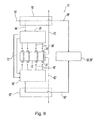
- the above-described cooling method is also illustrated schematically by the oil flow chart in Fig. 9 with reference to the electrical machine shown in Figs. 4 to 7 .
- the oil is directed through entry port 60' of first end cap 50'.
- the oil either flows through bearing channel 68' toward central bore 58' of first end cap 50' to lubricate rotor shaft, or the oil flows through entry channel 64' into first annular channel 56' of motor 10'.
- the oil either flows through discharge channels 66', onto end turns 26' of coils 24' of stator 12', and out through drain port 42' of first end cap 50', or the oil flows through axial ducts 72' to second annular channel 56".
- the oil either flows through discharge channels 66", onto end turns 26' of coils 24' of stator 12', and out through drain port 42" of second end cap 50", or the oil flows through bearing channel 68" of second end cap 50" toward central bore 58" of second end cap 50" to lubricate rotor shaft.
Landscapes
- Engineering & Computer Science (AREA)
- Power Engineering (AREA)
- Motor Or Generator Cooling System (AREA)
- Motor Or Generator Frames (AREA)
Claims (13)
- Kühlungssystem für eine elektrischen Maschine, wobei die elektrische Maschine (10, 10') umfasst: einen Stator (12, 12') mit mehreren Spulen (24, 24'), wobei der Stator (12, 12') eine axiale Bohrung (14, 14') definiert, die zum Aufnehmen eines Rotors konfiguriert ist;
ein Außengehäuse (30, 30') mit axialen Enden (36, 36'), wobei das Außengehäuse (30, 30') eine axiale Bohrung (34, 34') definiert, die zum Aufnehmen des Stators (12, 12') konfiguriert ist; und eine Endkappe (50, 50', 50"), die zum Koppeln mit mindestens einem der axialen Enden (36, 36') des Außengehäuses (30, 30') konfiguriert ist, wobei die Endkappe (50, 50', 50") einen Fluideinlass (60, 60') aufweist, der zum Aufnehmen eines flüssigen Kühlmittels konfiguriert ist; und
mehrere Fluidauslässe (66, 66', 66"), wobei mindestens einer der mehreren Fluidauslässe (66, 66', 66") zum Zuführen des flüssigen Kühlmittels von dem Fluideinlass (60, 60') zu mindestens einer der mehreren Spulen (24, 24') konfiguriert ist,
dadurch gekennzeichnet, dass
jede Endkappe (50) einen Kappenabschnitt (50a) aufweist, der auf einem axialen Ende (36) des Außengehäuses (30) aufliegt, und dadurch, dass sich ein zylindrischer Abschnitt (50b) innerhalb der axialen Bohrung (34) des Außengehäuses (30) erstreckt, wobei der zylindrische Abschnitt (50b) der Endkappe (50) eine Umfangskerbe (57) aufweist, die mit der Innenwand (32) des Außengehäuses (30) zusammenwirkt, um einen inneren ringförmigen Kanal (56) zu definieren, der sich im Wesentlichen um den Umfang des Motors (10) erstreckt, wobei sich die Fluidauslässe (66, 66', 66") von dem ringförmigen Kanal (56) erstrecken. - System nach Anspruch 1, dadurch gekennzeichnet, dass die mehreren Fluidauslässe (66, 66', 66") radial von der elektrischen Maschine (10, 10') beabstandet sind.
- System nach Anspruch 1 oder 2, dadurch gekennzeichnet, dass die mehreren Spulen (24, 24') radial um den Stator (12, 12') in radialer Ausrichtung mit den mehreren Fluidauslässen (66, 66', 66") beabstandet sind.
- System nach einem der Ansprüche 1 bis 3, dadurch gekennzeichnet, dass die Endkappe (50, 50', 50") eine zentrale Bohrung (58, 58', 58"), die zum Aufnehmen einer Welle des Rotors konfiguriert ist, und einen Lagerkanal (68, 68', 68") aufweist, der zum Leiten des flüssigen Kühlmittels aus dem Fluideinlass (60, 60') zur zentralen Bohrung (58, 58', 58") der Endkappe (50, 50', 50 ") konfiguriert ist, um die Welle des Rotors zu schmieren.
- System nach einem der Ansprüche 1 bis 4, dadurch gekennzeichnet, dass das flüssige Kühlmittel aus dem Fluideinlass (60, 60') durch einen oder mehrere Fluidauslässe (66, 66', 66") zur Abgabe an die mehreren Spulen (24, 24') strömt.
- System nach einem der Ansprüche 1 bis 5, ferner gekennzeichnet durch das Umfassen eines ringförmigen Kanals (56, 56', 56"), der im Wesentlichen radial den Stator (12, 12') der elektrischen Maschine (10, 10') umgibt, wobei der ringförmige Kanal (56, 56', 56") mindestens teilweise von der Endkappe (50, 50', 50") definiert wird und mit dem Fluideinlass (60, 60') und den mehreren Fluidauslässen (66, 66', 66") kommuniziert.
- System nach einem der Ansprüche 1 bis 6, dadurch gekennzeichnet, dass das Außengehäuse (30, 30') mit der Endkappe (50, 50', 50") zusammenwirkt, um den ringförmigen Kanal (56, 56', 56") zu definieren.
- System nach einem der Ansprüche 1 bis 7, dadurch gekennzeichnet, dass der Fluideinlass (60, 60') und/oder die mehreren Fluidauslässe (66, 66', 66") von der Endkappe (50, 50', 50") definiert werden.
- Verfahren zum Kühlen einer elektrischen Maschine, wobei die elektrische Maschine (10, 10') umfasst:einen Stator (12, 12') mit mehreren Spulen (24, 24'), wobei der Stator (12, 12') eine axiale Bohrung (14, 14') definiert, die zum Aufnehmen eines Rotors konfiguriert ist;ein Außengehäuse (30, 30') mit axialen Enden (36, 36'), wobei das Außengehäuse (30, 30') eine axiale Bohrung (34, 34') definiert, die zum Aufnehmen des Stators (12, 12') konfiguriert ist; und eine Endkappe (50, 50', 50"), die zum Koppeln mit mindestens einem der axialen Enden (36, 36') des Außengehäuses (30, 30') konfiguriert ist, wobei die Endkappe (50, 50', 50") einen Fluideinlass (60, 60') aufweist, der zum Aufnehmen eines flüssigen Kühlmittels konfiguriert ist; undmehrere Fluidauslässe (66, 66', 66"), wobei mindestens einer der mehreren Fluidauslässe (66, 66', 66") zum Abgeben des flüssigen Kühlmittels von dem Fluideinlass (60, 60') zu mindestens einer der mehreren Spulen (24, 24') konfiguriert ist, wobei der zylindrische Abschnitt (50b) der Endkappe (50) eine Umfangskerbe (57) aufweist, die mit der Innenwand (32) des Außengehäuses (30, 30') zusammenwirkt, um einen inneren ringförmigen Kanal (56) zu definieren, der sich um den Umfang des Motors (10) erstreckt, wobei sich die Fluidauslässe (66, 66', 66") von dem ringförmigen Kanal (56) erstrecken, wobei das Verfahren die Schritte des Abgebens eines flüssigen Kühlmittels an die Endkappe (50, 50', 50") der elektrischen Maschine (10, 10'); und des Sprühens des flüssigen Kühlmittels von der Endkappe (50, 50', 50") auf die mehreren Spulen (24, 24') des Stators (12, 12') beinhaltet.
- Verfahren nach Anspruch 9, dadurch gekennzeichnet, dass der Abgabeschritt das Abgeben des flüssigen Kühlmittels zu einem ringförmigen Kanal (56, 56', 56"), der den Stator (12, 12') der elektrischen Maschine (10, 10') im Wesentlichen radial umgibt, beinhaltet.
- Verfahren nach Anspruch 9 oder 10, dadurch gekennzeichnet, dass der Sprühschritt das Sprühen des flüssigen Kühlmittels aus mehreren radial beabstandeten Fluidauslässen (66, 66', 66") an der Endkappe (50, 50', 50") auf die mehreren Spulen (24, 24') des Stators (12, 12') beinhaltet.
- Verfahren nach einem der Ansprüche 9 bis 11, dadurch gekennzeichnet, dass eine Endkappe (50, 50') mit einem axialen Ende (36, 36') des Außengehäuses (30, 30') gekoppelt ist und eine andere Endkappe (50, 50") mit einem anderen axialen Ende (36, 36') des Außengehäuses (30, 30') gekoppelt ist, und der Sprühschritt das Sprühen des flüssigen Kühlmittels aus den beiden Endkappen (50, 50', 50") auf die mehreren Spulen (24, 24') des Stators (12, 12') beinhaltet.
- Verfahren nach einem der Ansprüche 9 bis 12, gekennzeichnet durch den weiteren Schritt des kontinuierlichen Entleerens des flüssigen Kühlmittels aus der elektrischen Maschine (10, 10') nach dem Sprühschritt.
Applications Claiming Priority (1)
| Application Number | Priority Date | Filing Date | Title |
|---|---|---|---|
| US12/486,263 US8129874B2 (en) | 2009-06-17 | 2009-06-17 | Internal oil cooling via housing end brackets for an electric machine |
Publications (3)
| Publication Number | Publication Date |
|---|---|
| EP2264870A2 EP2264870A2 (de) | 2010-12-22 |
| EP2264870A3 EP2264870A3 (de) | 2013-12-25 |
| EP2264870B1 true EP2264870B1 (de) | 2015-04-15 |
Family
ID=42277297
Family Applications (1)
| Application Number | Title | Priority Date | Filing Date |
|---|---|---|---|
| EP10165512.4A Not-in-force EP2264870B1 (de) | 2009-06-17 | 2010-06-10 | Kühlungssystem für eine elektrische Maschine |
Country Status (4)
| Country | Link |
|---|---|
| US (1) | US8129874B2 (de) |
| EP (1) | EP2264870B1 (de) |
| JP (1) | JP2011004594A (de) |
| CA (1) | CA2706032A1 (de) |
Families Citing this family (29)
| Publication number | Priority date | Publication date | Assignee | Title |
|---|---|---|---|---|
| JP5640835B2 (ja) * | 2011-03-14 | 2014-12-17 | トヨタ自動車株式会社 | 回転電機冷却装置および回転電機 |
| US20120318479A1 (en) * | 2011-06-14 | 2012-12-20 | Fukuta Electric & Machinery Co., Ltd. | Liquid cooled motor assembly and cover thereof |
| US9048710B2 (en) * | 2011-08-29 | 2015-06-02 | Remy Technologies, Llc | Electric machine module cooling system and method |
| JP5706793B2 (ja) * | 2011-09-20 | 2015-04-22 | 日立建機株式会社 | 発電電動機とこれを用いた電動車両 |
| US8901789B2 (en) | 2011-10-07 | 2014-12-02 | Remy Technologies, Llc | Electric machine module |
| JP5955155B2 (ja) * | 2012-08-09 | 2016-07-20 | アスモ株式会社 | ブラシレスモータ |
| CN104823360B (zh) | 2012-09-06 | 2018-02-13 | 开利公司 | 电动机转子和气隙冷却 |
| US9006943B2 (en) | 2012-09-12 | 2015-04-14 | Remy Technologies, L.L.C. | Electro-dynamic machine with coolant chargeable bladder |
| JP2015226376A (ja) * | 2014-05-28 | 2015-12-14 | 株式会社日立製作所 | アキシャルギャップモータ |
| JP2016003588A (ja) * | 2014-06-16 | 2016-01-12 | 株式会社デンソー | スタータモータ |
| WO2016068846A1 (en) * | 2014-10-27 | 2016-05-06 | Galvan Mario A | An electrical system and method for sustaining an external load |
| GB2535975A (en) * | 2015-02-02 | 2016-09-07 | Green Motorsport Ltd | Motor |
| IN2015MU01664A (de) * | 2015-04-24 | 2015-05-08 | Sona Pumps | |
| US10516320B2 (en) * | 2016-05-09 | 2019-12-24 | Borgwarner Inc. | Cooling system for an electric motor |
| DE102016211593A1 (de) * | 2016-06-28 | 2017-12-28 | Robert Bosch Gmbh | Elektrische Maschine |
| TWI629860B (zh) * | 2016-12-30 | 2018-07-11 | 財團法人工業技術研究院 | 電動機 |
| US10498186B2 (en) * | 2017-03-10 | 2019-12-03 | Weg Equipamentos Elétricos S.a. | Cap for a rotating electric machine |
| US10594191B2 (en) * | 2017-03-27 | 2020-03-17 | Ford Global Technologies, Llc | Rotor endplate for electric machine |
| DE102018212654A1 (de) * | 2018-07-30 | 2020-01-30 | Zf Friedrichshafen Ag | Kühlung einer elektrischen Maschine |
| EP4535619A3 (de) * | 2019-01-14 | 2025-07-23 | Shanghai Pangood Power Technology Co., Ltd. | Kühlsystem, statoranordnung und axialmagnetfeldmotor |
| US11750059B2 (en) | 2020-02-07 | 2023-09-05 | Deere & Company | End shield with spray feature |
| US12049925B2 (en) * | 2020-12-30 | 2024-07-30 | Dana Heavy Vehicle Systems Group, Llc | Systems and method for an electric motor with spray ring |
| US11873826B2 (en) | 2021-02-26 | 2024-01-16 | Deere & Company | Cooling arrangement for electric machines |
| JP7031074B1 (ja) * | 2021-05-17 | 2022-03-07 | 三菱電機株式会社 | 回転電機 |
| JP7439277B2 (ja) * | 2021-06-09 | 2024-02-27 | 浙江吉利控股集団有限公司 | ステータコア、電動機、パワートレイン、自動車及び車両 |
| US12149154B2 (en) | 2021-07-22 | 2024-11-19 | General Electric Company | Electric machine having a hybrid insulative-conductive manifold |
| JP7192941B1 (ja) | 2021-09-22 | 2022-12-20 | 株式会社明電舎 | 回転電機 |
| US12407215B2 (en) * | 2022-02-23 | 2025-09-02 | Vinfast Trading And Production Joint Stock Company | Cooling jacket for electric motor having configuration for reducing electromagnetic noise |
| EP4621239A1 (de) * | 2024-03-18 | 2025-09-24 | Carrier Corporation | Motorkühlung in schraubenverdichtern |
Family Cites Families (17)
| Publication number | Priority date | Publication date | Assignee | Title |
|---|---|---|---|---|
| US2947213A (en) * | 1956-12-21 | 1960-08-02 | Rolls Royce | Optical apparatus for checking borecross-sections |
| US3648085A (en) | 1970-03-26 | 1972-03-07 | Lear Siegler Inc | Liquid cooling arrangement for dynamoelectric machine |
| JPS6188468U (de) * | 1984-11-16 | 1986-06-09 | ||
| JPH0810978B2 (ja) * | 1988-09-13 | 1996-01-31 | ファナック株式会社 | 液冷式電動機 |
| US5003207A (en) | 1989-10-26 | 1991-03-26 | Sundstrand Corporation | Stator end winding cooling arrangement for a variable speed generator |
| US5181837A (en) * | 1991-04-18 | 1993-01-26 | Vickers, Incorporated | Electric motor driven inline hydraulic apparatus |
| JP2602410Y2 (ja) * | 1993-10-22 | 2000-01-17 | 神鋼電機株式会社 | 内部液冷式電動機の冷却構造 |
| JP3016463B2 (ja) * | 1993-11-30 | 2000-03-06 | 三菱電機株式会社 | 発電機 |
| CA2116900A1 (en) * | 1994-03-03 | 1995-09-04 | Carlo C. Di Pietro | Electric vehicle motor |
| US6579202B2 (en) * | 2000-12-18 | 2003-06-17 | General Motors Corporation | Lubrication and cooling system for power receiving and delivery units in an electro-mechanical vehicular transmission |
| US6750572B2 (en) * | 2002-03-01 | 2004-06-15 | Honeywell International, Inc. | Generator with improved lubrication and cooling system |
| US7009317B2 (en) * | 2004-01-14 | 2006-03-07 | Caterpillar Inc. | Cooling system for an electric motor |
| JP4441338B2 (ja) * | 2004-06-18 | 2010-03-31 | 本田技研工業株式会社 | 回転機 |
| US7287382B2 (en) * | 2004-07-19 | 2007-10-30 | John Henriquez | Gas turbine combustor end cover |
| JP2006311750A (ja) * | 2005-04-28 | 2006-11-09 | Nissan Motor Co Ltd | 回転電機の冷却装置 |
| US7834492B2 (en) * | 2006-07-31 | 2010-11-16 | Caterpillar Inc | Electric machine having a liquid-cooled rotor |
| US20080143201A1 (en) * | 2006-12-18 | 2008-06-19 | Gannon Ramy | Methods and apparatus for cooling an electric motor |
-
2009
- 2009-06-17 US US12/486,263 patent/US8129874B2/en active Active
-
2010
- 2010-06-02 CA CA2706032A patent/CA2706032A1/en not_active Abandoned
- 2010-06-10 EP EP10165512.4A patent/EP2264870B1/de not_active Not-in-force
- 2010-06-16 JP JP2010137284A patent/JP2011004594A/ja active Pending
Also Published As
| Publication number | Publication date |
|---|---|
| CA2706032A1 (en) | 2010-12-17 |
| US8129874B2 (en) | 2012-03-06 |
| US20100320851A1 (en) | 2010-12-23 |
| EP2264870A2 (de) | 2010-12-22 |
| JP2011004594A (ja) | 2011-01-06 |
| EP2264870A3 (de) | 2013-12-25 |
Similar Documents
| Publication | Publication Date | Title |
|---|---|---|
| EP2264870B1 (de) | Kühlungssystem für eine elektrische Maschine | |
| EP2242164B1 (de) | Elektrische drehmaschine | |
| EP3675332B1 (de) | Rotor für eine elektrische maschine | |
| JP3967624B2 (ja) | 電動機 | |
| US12580451B2 (en) | Rotor device for an electric machine including a cooling fluid line, a collecting ring, and an adapter | |
| CN101931281B (zh) | 油冷却的发电机 | |
| EP2747251B1 (de) | Elektrische Drehmaschine für Fahrzeuge mit Flüssigkeitskühlung | |
| EP2369723B1 (de) | Kühlanordnung für eine elektrische Maschine | |
| US9419499B2 (en) | Rotating electric machine having a cooling device and cooling liquid collection tanks | |
| EP3413441B1 (de) | Kühlsystem und -verfahren für eine elektromaschine | |
| US9780625B2 (en) | Cooling stator coils of an electric motor | |
| US20120062055A1 (en) | Cooling structure for rotating electric machine | |
| WO2012047481A2 (en) | Coolant drainage system and method for electric machines | |
| US11909262B2 (en) | Thermal management for generator/ motor stators | |
| US20130147289A1 (en) | Electric machine module cooling system and method | |
| US3789249A (en) | Apparatus for cooling a hermetic motor | |
| US20140117795A1 (en) | Motor cooling features | |
| US9621011B2 (en) | Stator assembly | |
| JP2019161948A (ja) | 回転電機 | |
| US8513840B2 (en) | Electric machine cooling system and method | |
| CN116054467A (zh) | 液冷电机以及包括该液冷电机的电驱系统 | |
| CN216625417U (zh) | 转子及油冷电机 | |
| US12614940B2 (en) | Cooling of high-power permanent magnet machine rotor | |
| CN220440497U (zh) | 定子的冷却结构、壳体、电机及车辆 | |
| CN221806576U (zh) | 永磁电机 |
Legal Events
| Date | Code | Title | Description |
|---|---|---|---|
| PUAI | Public reference made under article 153(3) epc to a published international application that has entered the european phase |
Free format text: ORIGINAL CODE: 0009012 |
|
| AK | Designated contracting states |
Kind code of ref document: A2 Designated state(s): AL AT BE BG CH CY CZ DE DK EE ES FI FR GB GR HR HU IE IS IT LI LT LU LV MC MK MT NL NO PL PT RO SE SI SK SM TR |
|
| AX | Request for extension of the european patent |
Extension state: BA ME RS |
|
| PUAL | Search report despatched |
Free format text: ORIGINAL CODE: 0009013 |
|
| AK | Designated contracting states |
Kind code of ref document: A3 Designated state(s): AL AT BE BG CH CY CZ DE DK EE ES FI FR GB GR HR HU IE IS IT LI LT LU LV MC MK MT NL NO PL PT RO SE SI SK SM TR |
|
| AX | Request for extension of the european patent |
Extension state: BA ME RS |
|
| RIC1 | Information provided on ipc code assigned before grant |
Ipc: H02K 5/16 20060101ALI20131119BHEP Ipc: H02K 9/19 20060101AFI20131119BHEP Ipc: H02K 5/20 20060101ALI20131119BHEP Ipc: H02K 5/15 20060101ALI20131119BHEP |
|
| 17P | Request for examination filed |
Effective date: 20140625 |
|
| RBV | Designated contracting states (corrected) |
Designated state(s): AL AT BE BG CH CY CZ DE DK EE ES FI FR GB GR HR HU IE IS IT LI LT LU LV MC MK MT NL NO PL PT RO SE SI SK SM TR |
|
| RIC1 | Information provided on ipc code assigned before grant |
Ipc: H02K 5/20 20060101ALI20140715BHEP Ipc: H02K 5/15 20060101ALI20140715BHEP Ipc: H02K 5/16 20060101ALI20140715BHEP Ipc: H02K 9/19 20060101AFI20140715BHEP |
|
| GRAP | Despatch of communication of intention to grant a patent |
Free format text: ORIGINAL CODE: EPIDOSNIGR1 |
|
| INTG | Intention to grant announced |
Effective date: 20141103 |
|
| GRAS | Grant fee paid |
Free format text: ORIGINAL CODE: EPIDOSNIGR3 |
|
| GRAA | (expected) grant |
Free format text: ORIGINAL CODE: 0009210 |
|
| AK | Designated contracting states |
Kind code of ref document: B1 Designated state(s): AL AT BE BG CH CY CZ DE DK EE ES FI FR GB GR HR HU IE IS IT LI LT LU LV MC MK MT NL NO PL PT RO SE SI SK SM TR |
|
| REG | Reference to a national code |
Ref country code: GB Ref legal event code: FG4D Ref country code: CH Ref legal event code: EP |
|
| REG | Reference to a national code |
Ref country code: IE Ref legal event code: FG4D |
|
| REG | Reference to a national code |
Ref country code: AT Ref legal event code: REF Ref document number: 722442 Country of ref document: AT Kind code of ref document: T Effective date: 20150515 |
|
| REG | Reference to a national code |
Ref country code: DE Ref legal event code: R096 Ref document number: 602010023912 Country of ref document: DE Effective date: 20150528 |
|
| REG | Reference to a national code |
Ref country code: SE Ref legal event code: TRGR |
|
| REG | Reference to a national code |
Ref country code: NL Ref legal event code: VDEP Effective date: 20150415 |
|
| REG | Reference to a national code |
Ref country code: AT Ref legal event code: MK05 Ref document number: 722442 Country of ref document: AT Kind code of ref document: T Effective date: 20150415 |
|
| REG | Reference to a national code |
Ref country code: LT Ref legal event code: MG4D |
|
| PG25 | Lapsed in a contracting state [announced via postgrant information from national office to epo] |
Ref country code: NL Free format text: LAPSE BECAUSE OF FAILURE TO SUBMIT A TRANSLATION OF THE DESCRIPTION OR TO PAY THE FEE WITHIN THE PRESCRIBED TIME-LIMIT Effective date: 20150415 |
|
| PG25 | Lapsed in a contracting state [announced via postgrant information from national office to epo] |
Ref country code: PT Free format text: LAPSE BECAUSE OF FAILURE TO SUBMIT A TRANSLATION OF THE DESCRIPTION OR TO PAY THE FEE WITHIN THE PRESCRIBED TIME-LIMIT Effective date: 20150817 Ref country code: HR Free format text: LAPSE BECAUSE OF FAILURE TO SUBMIT A TRANSLATION OF THE DESCRIPTION OR TO PAY THE FEE WITHIN THE PRESCRIBED TIME-LIMIT Effective date: 20150415 Ref country code: FI Free format text: LAPSE BECAUSE OF FAILURE TO SUBMIT A TRANSLATION OF THE DESCRIPTION OR TO PAY THE FEE WITHIN THE PRESCRIBED TIME-LIMIT Effective date: 20150415 Ref country code: ES Free format text: LAPSE BECAUSE OF FAILURE TO SUBMIT A TRANSLATION OF THE DESCRIPTION OR TO PAY THE FEE WITHIN THE PRESCRIBED TIME-LIMIT Effective date: 20150415 Ref country code: NO Free format text: LAPSE BECAUSE OF FAILURE TO SUBMIT A TRANSLATION OF THE DESCRIPTION OR TO PAY THE FEE WITHIN THE PRESCRIBED TIME-LIMIT Effective date: 20150715 Ref country code: LT Free format text: LAPSE BECAUSE OF FAILURE TO SUBMIT A TRANSLATION OF THE DESCRIPTION OR TO PAY THE FEE WITHIN THE PRESCRIBED TIME-LIMIT Effective date: 20150415 |
|
| PG25 | Lapsed in a contracting state [announced via postgrant information from national office to epo] |
Ref country code: AT Free format text: LAPSE BECAUSE OF FAILURE TO SUBMIT A TRANSLATION OF THE DESCRIPTION OR TO PAY THE FEE WITHIN THE PRESCRIBED TIME-LIMIT Effective date: 20150415 Ref country code: GR Free format text: LAPSE BECAUSE OF FAILURE TO SUBMIT A TRANSLATION OF THE DESCRIPTION OR TO PAY THE FEE WITHIN THE PRESCRIBED TIME-LIMIT Effective date: 20150716 Ref country code: IS Free format text: LAPSE BECAUSE OF FAILURE TO SUBMIT A TRANSLATION OF THE DESCRIPTION OR TO PAY THE FEE WITHIN THE PRESCRIBED TIME-LIMIT Effective date: 20150815 Ref country code: LV Free format text: LAPSE BECAUSE OF FAILURE TO SUBMIT A TRANSLATION OF THE DESCRIPTION OR TO PAY THE FEE WITHIN THE PRESCRIBED TIME-LIMIT Effective date: 20150415 |
|
| REG | Reference to a national code |
Ref country code: DE Ref legal event code: R119 Ref document number: 602010023912 Country of ref document: DE |
|
| PG25 | Lapsed in a contracting state [announced via postgrant information from national office to epo] |
Ref country code: MC Free format text: LAPSE BECAUSE OF FAILURE TO SUBMIT A TRANSLATION OF THE DESCRIPTION OR TO PAY THE FEE WITHIN THE PRESCRIBED TIME-LIMIT Effective date: 20150415 Ref country code: IT Free format text: LAPSE BECAUSE OF FAILURE TO SUBMIT A TRANSLATION OF THE DESCRIPTION OR TO PAY THE FEE WITHIN THE PRESCRIBED TIME-LIMIT Effective date: 20150415 Ref country code: EE Free format text: LAPSE BECAUSE OF FAILURE TO SUBMIT A TRANSLATION OF THE DESCRIPTION OR TO PAY THE FEE WITHIN THE PRESCRIBED TIME-LIMIT Effective date: 20150415 Ref country code: DK Free format text: LAPSE BECAUSE OF FAILURE TO SUBMIT A TRANSLATION OF THE DESCRIPTION OR TO PAY THE FEE WITHIN THE PRESCRIBED TIME-LIMIT Effective date: 20150415 |
|
| REG | Reference to a national code |
Ref country code: CH Ref legal event code: PL |
|
| PLBE | No opposition filed within time limit |
Free format text: ORIGINAL CODE: 0009261 |
|
| STAA | Information on the status of an ep patent application or granted ep patent |
Free format text: STATUS: NO OPPOSITION FILED WITHIN TIME LIMIT |
|
| PG25 | Lapsed in a contracting state [announced via postgrant information from national office to epo] |
Ref country code: SK Free format text: LAPSE BECAUSE OF FAILURE TO SUBMIT A TRANSLATION OF THE DESCRIPTION OR TO PAY THE FEE WITHIN THE PRESCRIBED TIME-LIMIT Effective date: 20150415 Ref country code: RO Free format text: LAPSE BECAUSE OF NON-PAYMENT OF DUE FEES Effective date: 20150415 Ref country code: PL Free format text: LAPSE BECAUSE OF FAILURE TO SUBMIT A TRANSLATION OF THE DESCRIPTION OR TO PAY THE FEE WITHIN THE PRESCRIBED TIME-LIMIT Effective date: 20150415 Ref country code: CZ Free format text: LAPSE BECAUSE OF FAILURE TO SUBMIT A TRANSLATION OF THE DESCRIPTION OR TO PAY THE FEE WITHIN THE PRESCRIBED TIME-LIMIT Effective date: 20150415 Ref country code: LU Free format text: LAPSE BECAUSE OF FAILURE TO SUBMIT A TRANSLATION OF THE DESCRIPTION OR TO PAY THE FEE WITHIN THE PRESCRIBED TIME-LIMIT Effective date: 20150610 |
|
| 26N | No opposition filed |
Effective date: 20160118 |
|
| REG | Reference to a national code |
Ref country code: IE Ref legal event code: MM4A |
|
| REG | Reference to a national code |
Ref country code: FR Ref legal event code: ST Effective date: 20160229 |
|
| PG25 | Lapsed in a contracting state [announced via postgrant information from national office to epo] |
Ref country code: IE Free format text: LAPSE BECAUSE OF NON-PAYMENT OF DUE FEES Effective date: 20150610 Ref country code: LI Free format text: LAPSE BECAUSE OF NON-PAYMENT OF DUE FEES Effective date: 20150630 Ref country code: DE Free format text: LAPSE BECAUSE OF NON-PAYMENT OF DUE FEES Effective date: 20160101 Ref country code: CH Free format text: LAPSE BECAUSE OF NON-PAYMENT OF DUE FEES Effective date: 20150630 |
|
| PG25 | Lapsed in a contracting state [announced via postgrant information from national office to epo] |
Ref country code: FR Free format text: LAPSE BECAUSE OF NON-PAYMENT OF DUE FEES Effective date: 20150630 Ref country code: SI Free format text: LAPSE BECAUSE OF FAILURE TO SUBMIT A TRANSLATION OF THE DESCRIPTION OR TO PAY THE FEE WITHIN THE PRESCRIBED TIME-LIMIT Effective date: 20150415 |
|
| PG25 | Lapsed in a contracting state [announced via postgrant information from national office to epo] |
Ref country code: BE Free format text: LAPSE BECAUSE OF FAILURE TO SUBMIT A TRANSLATION OF THE DESCRIPTION OR TO PAY THE FEE WITHIN THE PRESCRIBED TIME-LIMIT Effective date: 20150415 |
|
| PG25 | Lapsed in a contracting state [announced via postgrant information from national office to epo] |
Ref country code: MT Free format text: LAPSE BECAUSE OF FAILURE TO SUBMIT A TRANSLATION OF THE DESCRIPTION OR TO PAY THE FEE WITHIN THE PRESCRIBED TIME-LIMIT Effective date: 20150415 |
|
| PG25 | Lapsed in a contracting state [announced via postgrant information from national office to epo] |
Ref country code: SM Free format text: LAPSE BECAUSE OF FAILURE TO SUBMIT A TRANSLATION OF THE DESCRIPTION OR TO PAY THE FEE WITHIN THE PRESCRIBED TIME-LIMIT Effective date: 20150415 Ref country code: BG Free format text: LAPSE BECAUSE OF FAILURE TO SUBMIT A TRANSLATION OF THE DESCRIPTION OR TO PAY THE FEE WITHIN THE PRESCRIBED TIME-LIMIT Effective date: 20150415 Ref country code: HU Free format text: LAPSE BECAUSE OF FAILURE TO SUBMIT A TRANSLATION OF THE DESCRIPTION OR TO PAY THE FEE WITHIN THE PRESCRIBED TIME-LIMIT; INVALID AB INITIO Effective date: 20100610 |
|
| PG25 | Lapsed in a contracting state [announced via postgrant information from national office to epo] |
Ref country code: CY Free format text: LAPSE BECAUSE OF FAILURE TO SUBMIT A TRANSLATION OF THE DESCRIPTION OR TO PAY THE FEE WITHIN THE PRESCRIBED TIME-LIMIT Effective date: 20150415 |
|
| PG25 | Lapsed in a contracting state [announced via postgrant information from national office to epo] |
Ref country code: TR Free format text: LAPSE BECAUSE OF FAILURE TO SUBMIT A TRANSLATION OF THE DESCRIPTION OR TO PAY THE FEE WITHIN THE PRESCRIBED TIME-LIMIT Effective date: 20150415 |
|
| PG25 | Lapsed in a contracting state [announced via postgrant information from national office to epo] |
Ref country code: MK Free format text: LAPSE BECAUSE OF FAILURE TO SUBMIT A TRANSLATION OF THE DESCRIPTION OR TO PAY THE FEE WITHIN THE PRESCRIBED TIME-LIMIT Effective date: 20150415 |
|
| PG25 | Lapsed in a contracting state [announced via postgrant information from national office to epo] |
Ref country code: AL Free format text: LAPSE BECAUSE OF FAILURE TO SUBMIT A TRANSLATION OF THE DESCRIPTION OR TO PAY THE FEE WITHIN THE PRESCRIBED TIME-LIMIT Effective date: 20150415 |
|
| PGFP | Annual fee paid to national office [announced via postgrant information from national office to epo] |
Ref country code: SE Payment date: 20220627 Year of fee payment: 13 Ref country code: GB Payment date: 20220628 Year of fee payment: 13 |
|
| REG | Reference to a national code |
Ref country code: SE Ref legal event code: EUG |
|
| GBPC | Gb: european patent ceased through non-payment of renewal fee |
Effective date: 20230610 |
|
| PG25 | Lapsed in a contracting state [announced via postgrant information from national office to epo] |
Ref country code: GB Free format text: LAPSE BECAUSE OF NON-PAYMENT OF DUE FEES Effective date: 20230610 |
|
| PG25 | Lapsed in a contracting state [announced via postgrant information from national office to epo] |
Ref country code: SE Free format text: LAPSE BECAUSE OF NON-PAYMENT OF DUE FEES Effective date: 20230611 |