EP2265009A2 - Appareil de traitement d'informations, procédé de traitement d'informations, support de stockage de programme et programme - Google Patents
Appareil de traitement d'informations, procédé de traitement d'informations, support de stockage de programme et programme Download PDFInfo
- Publication number
- EP2265009A2 EP2265009A2 EP10011416A EP10011416A EP2265009A2 EP 2265009 A2 EP2265009 A2 EP 2265009A2 EP 10011416 A EP10011416 A EP 10011416A EP 10011416 A EP10011416 A EP 10011416A EP 2265009 A2 EP2265009 A2 EP 2265009A2
- Authority
- EP
- European Patent Office
- Prior art keywords
- stream
- reproduction
- segments
- data
- recording
- Prior art date
- Legal status (The legal status is an assumption and is not a legal conclusion. Google has not performed a legal analysis and makes no representation as to the accuracy of the status listed.)
- Withdrawn
Links
Images


Classifications
-
- G—PHYSICS
- G11—INFORMATION STORAGE
- G11B—INFORMATION STORAGE BASED ON RELATIVE MOVEMENT BETWEEN RECORD CARRIER AND TRANSDUCER
- G11B27/00—Editing; Indexing; Addressing; Timing or synchronising; Monitoring; Measuring tape travel
- G11B27/10—Indexing; Addressing; Timing or synchronising; Measuring tape travel
- G11B27/102—Programmed access in sequence to addressed parts of tracks of operating record carriers
- G11B27/105—Programmed access in sequence to addressed parts of tracks of operating record carriers of operating discs
-
- G—PHYSICS
- G11—INFORMATION STORAGE
- G11B—INFORMATION STORAGE BASED ON RELATIVE MOVEMENT BETWEEN RECORD CARRIER AND TRANSDUCER
- G11B20/00—Signal processing not specific to the method of recording or reproducing; Circuits therefor
- G11B20/10—Digital recording or reproducing
-
- G—PHYSICS
- G11—INFORMATION STORAGE
- G11B—INFORMATION STORAGE BASED ON RELATIVE MOVEMENT BETWEEN RECORD CARRIER AND TRANSDUCER
- G11B27/00—Editing; Indexing; Addressing; Timing or synchronising; Monitoring; Measuring tape travel
- G11B27/02—Editing, e.g. varying the order of information signals recorded on, or reproduced from, record carriers
- G11B27/031—Electronic editing of digitised analogue information signals, e.g. audio or video signals
- G11B27/034—Electronic editing of digitised analogue information signals, e.g. audio or video signals on discs
-
- G—PHYSICS
- G11—INFORMATION STORAGE
- G11B—INFORMATION STORAGE BASED ON RELATIVE MOVEMENT BETWEEN RECORD CARRIER AND TRANSDUCER
- G11B27/00—Editing; Indexing; Addressing; Timing or synchronising; Monitoring; Measuring tape travel
- G11B27/10—Indexing; Addressing; Timing or synchronising; Measuring tape travel
- G11B27/19—Indexing; Addressing; Timing or synchronising; Measuring tape travel by using information detectable on the record carrier
- G11B27/28—Indexing; Addressing; Timing or synchronising; Measuring tape travel by using information detectable on the record carrier by using information signals recorded by the same method as the main recording
- G11B27/32—Indexing; Addressing; Timing or synchronising; Measuring tape travel by using information detectable on the record carrier by using information signals recorded by the same method as the main recording on separate auxiliary tracks of the same or an auxiliary record carrier
- G11B27/327—Table of contents
- G11B27/329—Table of contents on a disc [VTOC]
-
- H—ELECTRICITY
- H04—ELECTRIC COMMUNICATION TECHNIQUE
- H04N—PICTORIAL COMMUNICATION, e.g. TELEVISION
- H04N5/00—Details of television systems
- H04N5/76—Television signal recording
- H04N5/91—Television signal processing therefor
- H04N5/92—Transformation of the television signal for recording, e.g. modulation, frequency changing; Inverse transformation for playback
-
- H—ELECTRICITY
- H04—ELECTRIC COMMUNICATION TECHNIQUE
- H04N—PICTORIAL COMMUNICATION, e.g. TELEVISION
- H04N9/00—Details of colour television systems
- H04N9/79—Processing of colour television signals in connection with recording
- H04N9/80—Transformation of the television signal for recording, e.g. modulation, frequency changing; Inverse transformation for playback
- H04N9/82—Transformation of the television signal for recording, e.g. modulation, frequency changing; Inverse transformation for playback the individual colour picture signal components being recorded simultaneously only
- H04N9/8205—Transformation of the television signal for recording, e.g. modulation, frequency changing; Inverse transformation for playback the individual colour picture signal components being recorded simultaneously only involving the multiplexing of an additional signal and the colour video signal
- H04N9/8227—Transformation of the television signal for recording, e.g. modulation, frequency changing; Inverse transformation for playback the individual colour picture signal components being recorded simultaneously only involving the multiplexing of an additional signal and the colour video signal the additional signal being at least another television signal
-
- G—PHYSICS
- G11—INFORMATION STORAGE
- G11B—INFORMATION STORAGE BASED ON RELATIVE MOVEMENT BETWEEN RECORD CARRIER AND TRANSDUCER
- G11B2220/00—Record carriers by type
- G11B2220/20—Disc-shaped record carriers
- G11B2220/25—Disc-shaped record carriers characterised in that the disc is based on a specific recording technology
- G11B2220/2537—Optical discs
- G11B2220/2562—DVDs [digital versatile discs]; Digital video discs; MMCDs; HDCDs
-
- H—ELECTRICITY
- H04—ELECTRIC COMMUNICATION TECHNIQUE
- H04N—PICTORIAL COMMUNICATION, e.g. TELEVISION
- H04N5/00—Details of television systems
- H04N5/76—Television signal recording
- H04N5/84—Television signal recording using optical recording
- H04N5/85—Television signal recording using optical recording on discs or drums
-
- H—ELECTRICITY
- H04—ELECTRIC COMMUNICATION TECHNIQUE
- H04N—PICTORIAL COMMUNICATION, e.g. TELEVISION
- H04N9/00—Details of colour television systems
- H04N9/79—Processing of colour television signals in connection with recording
- H04N9/7921—Processing of colour television signals in connection with recording for more than one processing mode
-
- H—ELECTRICITY
- H04—ELECTRIC COMMUNICATION TECHNIQUE
- H04N—PICTORIAL COMMUNICATION, e.g. TELEVISION
- H04N9/00—Details of colour television systems
- H04N9/79—Processing of colour television signals in connection with recording
- H04N9/80—Transformation of the television signal for recording, e.g. modulation, frequency changing; Inverse transformation for playback
- H04N9/804—Transformation of the television signal for recording, e.g. modulation, frequency changing; Inverse transformation for playback involving pulse code modulation of the colour picture signal components
- H04N9/8042—Transformation of the television signal for recording, e.g. modulation, frequency changing; Inverse transformation for playback involving pulse code modulation of the colour picture signal components involving data reduction
-
- H—ELECTRICITY
- H04—ELECTRIC COMMUNICATION TECHNIQUE
- H04N—PICTORIAL COMMUNICATION, e.g. TELEVISION
- H04N9/00—Details of colour television systems
- H04N9/79—Processing of colour television signals in connection with recording
- H04N9/80—Transformation of the television signal for recording, e.g. modulation, frequency changing; Inverse transformation for playback
- H04N9/82—Transformation of the television signal for recording, e.g. modulation, frequency changing; Inverse transformation for playback the individual colour picture signal components being recorded simultaneously only
- H04N9/8205—Transformation of the television signal for recording, e.g. modulation, frequency changing; Inverse transformation for playback the individual colour picture signal components being recorded simultaneously only involving the multiplexing of an additional signal and the colour video signal
Definitions
- the present invention relates to an information processing apparatus, an information processing method, a program storage medium, and a program. More particularly, the invention relates to an information processing apparatus, an information processing method, a program storage medium, and a program for recording data having a plurality of reproduction paths to a recording medium.
- the method involves managing an actual content stream using clip information while controlling reproduction of the AV stream based on play lists.
- address information "SPN_ATS_start, SPN_STC_start” about discontinuities in the AV stream is recorded to the clip information, together with information "EP_map, TU_map” associating time information with address information in the AV stream, as well as time information clip marks for characteristic pictures in the AV stream.
- a typical recording medium carrying the above-mentioned plurality of data items formed by video and audio data is DVD-Video (digital versatile disk-video).
- the DVD-Video format includes specifications regarding multi-angle reproduction. Over a reproduction segment in which multi-angle reproduction is available, the user can select a desired angle for reproduction. In such a case, angles can be changed in seamless fashion by the recording/reproducing apparatus in use.
- Fig. 1 is an explanatory view of a multi-angle format for DVD-Video.
- a multi-angle reproduction segment is made up of a plurality of subordinate reproduction segments called a cell each.
- the multi-angle reproduction segment is formed by three cells #i+1 through #i+3 for angles #1 through #3 respectively.
- Actual AV stream data corresponding to the cells is called VOB's (video objects).
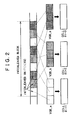
- Fig. 2 is an explanatory view of an interleaved block structure for implementing multi-angle reproduction of DVD-Video.
- An interleaved block is constituted by a plurality of interleaved units (ILVU's).
- the VOB's corresponding to the cells making up a multi-angle reproduction segment are divided into ILVU's.
- the multiple VOB's constituting the multi-angle reproduction segment are multiplexed in increments of ILVU's.
- Each ILVU begins with a closed GOP (group of pictures).
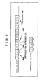
- the reproduction of DVD-Video with seamless angle change takes place illustratively as follows: suppose that the user changes reproduction paths from angle 2 to angle 1 to angle 3. In that case, the recording/reproducing apparatus jumps over the disk as shown in Fig. 3 so as to read data from ILVU1, ILVU2 and ILVU3 successively for reproduction. Each ILVU starts with DSI (data search information) which has an address of the destination ILVU to which to jump for the next angle.
- DSI data search information
- the present invention has been made in view of the above circumstances and provides inventive arrangements for optimally laying out data without fragmenting its AV stream while allowing reproduction paths to change seamlessly.
- an information processing apparatus for recording an AV stream to a recording medium
- the information processing apparatus comprising: generating means for generating the AV stream constituting each of a plurality of reproduction paths; controlling means for controlling the generation of the AV stream by the generating means; and recording means for recording to the recording medium the AV stream generated by the generating means; wherein the AV stream is constituted by data blocks making up predetermined units; and wherein the controlling means controls parameters for the AV stream generated by the generating means as well as a layout of the data blocks, in accordance with information indicative of reproducing characteristics in effect when the AV stream recorded on the recording medium is reproduced therefrom.
- the information indicative of the reproducing characteristics may denote relations between jump distances between the data blocks recorded in separate locations on the hand, and jump times corresponding respectively to the jump distances on the other hand, for use during reproduction of the AV stream in keeping with the reproduction paths.
- the parameters for the AV stream under control of the controlling means may preferably include a rate of the AV stream.
- the parameters for the AV stream under control of the controlling means may preferably include the number of the reproduction paths.
- the generating means may interleave the AV stream in such a manner that the plurality of reproduction paths are divided into a predetermined number of the data blocks laid out successively; and the controlling means may determine the number of the data blocks in controlling the layout of the interleaved data blocks.
- the information processing apparatus may further comprise inputting means for admitting an input operation made by a user; wherein, in response to the input operation made by the user through the inputting means, the controlling means may control the parameters for the AV stream generated by the generating means as well as the layout of the data blocks by giving priority to a predetermined parameter among the parameters.
- the information processing apparatus above may further comprise storing means for storing the information indicative of the reproducing characteristics; wherein the controlling means may control the parameters for the AV stream generated by the generating means as well as the layout of the data blocks on the basis of the information indicative of the reproducing characteristics which is stored in the storing means.
- the information processing apparatus may further comprise reproducing means for reproducing the AV stream recorded on the recording medium; wherein the controlling means may control the parameters for the AV stream generated by the generating means as well as the layout of the data blocks, in accordance with the information indicative of the reproducing characteristics in effect when the AV stream is reproduced by the reproducing means.
- the controlling means may preferably generate first management information which includes map information for indicating locations of entry points of the AV stream and which is used to control AV stream status, the controlling means further generating second management information for managing the reproduction paths by setting up change points of each of the reproduction paths in accordance with the entry points included in the map information; and the recording means may further record the first management information and the second management information to the recording medium.
- first management information which includes map information for indicating locations of entry points of the AV stream and which is used to control AV stream status
- the controlling means further generating second management information for managing the reproduction paths by setting up change points of each of the reproduction paths in accordance with the entry points included in the map information
- the recording means may further record the first management information and the second management information to the recording medium.
- the generating means may encode the AV stream in such a manner that the AV stream concludes within each of segments delimited by the change points; and the controlling means may create as said map information a correspondence table describing relations of correspondence between presentation timestamps of the entry points on the one hand and packet numbers on the other hand.
- the generating means may encode the AV stream in such a manner that each of the segments has a video stream made up of a closed group of packets called the closed GOP starting with an I picture, the first packet of the closed GOP being a video packet; and the AV stream generated by the generating means may be included in a transport stream.
- the generating means may preferably use an identical value representing packet ID's of the video packets in the transport stream as well as an identical value representing packet ID's of audio packets in the transport stream.
- the information processing apparatus may further comprise source packetizing means for turning the transport stream in each of the segments into source packets; wherein the recording means may record the transport stream which has been turned into source packets in each of the segments by the source packetizing means, to the recording medium as an AV stream file.
- the correspondence table may further include change information indicating whether it is possible to change the reproduction paths at each of the entry points; and the controlling means may set the change points on the basis of the change information.
- the controlling means may generate first management information which includes map information for indicating locations of starting points of the AV stream on each of the reproduction paths as well as locations of entry points of the AV streams and which is used to control AV stream status, the controlling means further generating second management information which includes designation information for designating a starting point and an end point of each of the AV streams and for designating the AV stream for each of the reproduction paths and which is used for reproduction management; and the recording means may further record the first management information and the second management information to the recording medium.
- first management information which includes map information for indicating locations of starting points of the AV stream on each of the reproduction paths as well as locations of entry points of the AV streams and which is used to control AV stream status
- the controlling means further generating second management information which includes designation information for designating a starting point and an end point of each of the AV streams and for designating the AV stream for each of the reproduction paths and which is used for reproduction management
- the recording means may further record the first management information and the second management information to the recording medium.
- the generating means may encode the AV stream in such a manner that the AV stream concludes within each of segments delimited by the change points; and the controlling means may create a correspondence table describing relations of correspondence between presentation timestamps of the entry points on the one hand and packet numbers on the other hand.
- the generating means may preferably encode the AV stream in such a manner that each of the segments has a video stream made up of a closed group of packets called the closed GOP starting with an I picture, the first packet of the closed GOP being a video packet; and the AV stream generated by the generating means may be included in a transport stream.
- the generating means may preferably encode the AV stream in such a manner that each of the segments has a video stream headed by a closed group of packets called the closed GOP, the rest of the video stream comprising unclosed GOP's.
- the information processing apparatus may further comprise source packetizing means for turning the transport stream in each of the segments into source packets; wherein the recording means may record the transport stream which has been turned into source packets in each of the segments by the source packetizing means, to the recording medium as an AV stream file.
- the controlling means may preferably create the correspondence table corresponding to each of the AV stream files.
- an AV stream constituting each of a plurality of reproduction paths is generated.
- the generation of the AV stream is suitably controlled.
- the AV stream thus generated is recorded to a recording medium.
- the AV stream is constituted by data blocks making up predetermined units. Parameters for the AV stream as well as a layout of the data blocks are controlled in accordance with information indicative of reproducing characteristics in effect when the AV stream recorded on the recording medium is reproduced therefrom.
- an information processing method for use with an information processing apparatus for recording an AV stream to a recording medium, the information processing method comprising the steps of: determining parameters for the AV stream as well as a layout of data blocks constituting the AV stream, in accordance with information indicative of reproducing characteristics in effect when the AV stream recorded on the recording medium is reproduced therefrom; generating the AV stream constituting each of a plurality of reproduction paths based on the parameters for the AV stream and on the layout of the data blocks determined in the determining step along with the parameters; and controlling the recording of the AV stream generated in the generating step to the recording medium.
- a program storage medium which stores a program for causing a computer to record an AV stream to a recording medium, the program comprising the steps of: determining parameters for the AV stream as well as a layout of data blocks constituting the AV stream, in accordance with information indicative of reproducing characteristics in effect when the AV stream recorded on the recording medium is reproduced therefrom; generating the AV stream constituting each of a plurality of reproduction paths based on the parameters for the AV stream and on the layout of the data blocks determined in the determining step along with the parameters; and controlling the recording of the AV stream generated in the generating step to the recording medium.
- a program for causing a computer to record an AV stream to a recording medium comprising the steps of: determining parameters for the AV stream as well as a layout of data blocks constituting the AV stream, in accordance with information indicative of reproducing characteristics in effect when the AV stream recorded on the recording medium is reproduced therefrom; generating the AV stream constituting each of a plurality of reproduction paths based on the parameters for the AV stream and on the layout of the data blocks determined in the determining step along with the parameters; and controlling the recording of the AV stream generated in the generating step to the recording medium.
- parameters for an AV stream as well as a layout of data blocks constituting the AV stream are determined in accordance with information indicative of reproducing characteristics in effect when the AV stream recorded on a recording medium is reproduced therefrom.
- the AV stream constituting each of a plurality of reproduction paths is generated based on the parameters for the AV stream and on the layout of the data blocks determined earlier along with the parameters.
- the recording of the generated AV stream to the recording medium is suitably controlled.
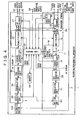
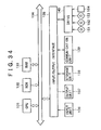
- FIG. 4 is a block diagram indicating an internal structure of a recording/reproducing apparatus 1 embodying this invention.
- the recording/reproducing apparatus 1 is structured to receive and store externally input analog or digital data.
- Analog video and audio signals are input to terminals 11 and 12 respectively.
- the video signal input to the terminal 11 is forwarded to an analysis unit 14 and an AV encoder 15.
- the audio signal is send to the analysis unit 14 and AV encoder 15 as well.
- the analysis unit 14 extracts characteristics such as scene changes from the input video and audio signals.
- the AV encoder 15 encodes the input video and audio signals so as to create an encoded video stream (V), an encoded audio stream (A), and system information (S) such as AV sync signals for output to a multiplexer 16.
- the encoded video stream is illustratively a video stream coded in MPEG-2 (Moving Picture Experts Group Phase 2).
- the encoded audio stream is illustratively an audio stream coded in MPEG-1 or in Dolby AC-3 (trademark).
- the multiplexer 16 multiplexes the input video and audio streams in accordance with input system information, creating a multiplexed data stream for output to a multiplexed stream analysis unit 18 and a source packetizer 19.
- the multiplexed stream is illustratively an MPEG-2 transport stream or an MPEG-2 program stream.
- the source packetizer 19 encodes the input multiplexed stream into an AV stream made up of source packets in keeping with the application format of a recording medium 100 to which to record the stream.
- the AV stream is subjected to ECC (error correction code) encoding by an ECC encoding unit 20 and to modulation by a modulation unit 21, before being output to a writing unit 22.
- the writing unit 22 writes AV stream files to the recording medium 100 such as a DVD in accordance with control signals from a control unit 23.
- a terminal 13 admits a transport stream such as digital TV broadcasts coming from a digital interface or from a digital TV tuner (neither shown).
- the transport stream input to the terminal 13 is recorded by one of two methods: either the stream is recorded in transparent fashion, or the stream is recorded after being re-encoded illustratively to reduce the recording bit rate.
- Information for designating the recording method is input to the control unit 23 from a terminal 24 serving as a user interface.
- the transport stream received through the terminal 13 is output to the multiplexed stream analysis unit 18 and source packetizer 19 via switches 25 and 17.
- Subsequent processing steps up to the recording of the AV stream to the recording medium 100 are the same as the above-mentioned steps for encoding the analog input audio and video signals and for recording the encoded signals, and thus will not be discussed further.
- the transport stream received through the terminal 13 is input to a demultiplexer 26 via the switch 25.
- the demultiplexer 26 demultiplexes the input transport stream so as to extract a video stream (V), an audio stream (A) and system information (S).
- the video stream (V) is output to an AV decoder 27 while the audio stream (A) and system information (S) are forwarded to the multiplexer 16.
- the AV decoder 27 decodes the input video stream and outputs a reproduced video signal out of the stream to the AV encoder 15.
- the AV encoder 15 encodes the input video signal into an encoded video stream (V) for output to the multiplexer 16.
- the multiplexer 16 multiplexes the audio stream and system information coming from the demultiplexer 26 as well as the video stream from the AV encoder 15 in order to create a multiplexed stream for output to the multiplexed stream analysis unit 18 and to the source packetizer 19 via the switch 17. Subsequent processing steps up to the recording of the AV stream to the recording medium 100 are the same as the above-mentioned steps for encoding the analog input audio and video signals and for recording the encoded signals, and thus will not be discussed further.
- the recording/reproducing apparatus 1 records AV stream files to the recording medium 100 along with application database information for explaining the files.
- the application database information is created by the control unit 23.
- the control unit 23 is supplied with moving picture characteristic information from the analysis unit 14, with AV stream characteristic information from the multiplexed stream analysis unit 18, and with user-input designation information from the terminal 24. As needed, the control unit 23 refers to diverse kinds of information stored in a memory 34.
- the moving picture characteristic information coming from the analysis unit 14 is generated thereby when the AV encoder 15 encodes video signals. More specifically, the analysis unit 14 analyzes the content of input video and audio signals and creates accordingly information about characteristic pictures (i.e., clip marks) in the input moving picture signals. What is created here is information for designating characteristic clip mark pictures such as program start points, scene change points, start and end points of commercial messages (CM), titles, telop indications, and thumbnail images in the input video signals.
- the information about the characteristic pictures (clip marks) further includes stereo-to-monaural change points and silent pauses in the audio signals.
- the picture designating information is input to the multiplexer 16 through the control unit 23.
- the multiplexer 16 sends back to the control unit 23 information for identifying the encoded pictures in the AV stream. More specifically, the information is address information which specifies either PTS (presentation timestamps) for the pictures or the addresses of the pictures when they are encoded in the AV stream.
- the control unit 23 associates in storage the types of the characteristic pictures with the information for identifying the encoded pictures in the AV stream.
- the AV stream characteristic information fed from the multiplexed stream analysis unit 18 is information which concerns the encoding of the AV stream to be recorded and which is generated by the multiplexed stream analysis unit 18.
- the AV stream characteristic information includes: timestamps and address information for the I pictures in the AV stream, system time clock discontinuity information, encoding parameters in the AV stream, and change point information about the encoding parameters in the AV stream.
- the multiplexed stream analysis unit 18 detects the above-mentioned clip mark pictures from the input transport stream and generates accordingly information for identifying the pictures designated by type and by clip mark.
- the user's designation information fed from the terminal 24 illustratively includes: conditions for determining an AV stream recording method, to be discussed later; information for specifying user-designated reproduction segments in the AV stream; text in characters for explaining what is contained in the reproduction segments; and information about book marks and resume points to be set for the scenes preferred by the user.
- the memory 34 holds information necessary for determining the AV stream recording method, such as information indicating relations between jump times and jump distances and determined by a function of a driving unit (not shown).
- the driving unit rotates the recording medium 100 so as to have the reading unit 28 positioned where appropriate on the recording medium 100.
- the information is retrieved from the memory 34 as needed by the control unit 23.
- the control unit 23 determines the AV stream recording method based on the above-described input information as well as on the information held in the memory 34.
- the control unit 23 further creates clips constituting a database for the AV stream, a database of play lists each containing a group of play items representative of reproduction segments of the AV stream, management information (info.dvr) about what is recorded on the recording medium 100, and thumbnail picture information.
- These pieces of information constitute application database information which, as with the AV stream, is subjected to ECC encoding by the ECC encoding unit 20 and to modulation by the modulation unit 21 before being input to the writing unit 22.
- the writing unit 22 records database files to the recording medium 100 in keeping with control signals coming from the control unit 23.
- the clips make up information for managing AV stream status
- the play lists constitute information for managing the reproduction paths of the AV stream.
- the application database information mentioned above will be discussed later in more detail.
- the control unit 23 first instructs the reading unit 28 to read the application database information from the recording medium 100.
- the reading unit 28 reads the application database information from the recording medium 100.
- the retrieved application database information is input to the control unit 23 after undergoing demodulation by a demodulation unit 29 and error correction by an ECC decoding unit 30.
- the control unit 23 outputs a table of play lists read from the recording medium 100 to the user interface through the terminal 24.
- the user selects desired play lists from the play list table on display.
- Information about the play lists designated by the user for reproduction is input through the terminal 24 to the control unit 23.
- the control unit 23 instructs the reading unit 28 to retrieve the AV stream files necessary for reproducing the play lists.
- the reading unit 28 reads the corresponding AV stream from the recording medium 100 and outputs the retrieved stream to the demodulation unit 29.
- the demodulation unit 29 carries out necessary steps to demodulate the input AV stream.
- the ECC decoding unit 30 performs ECC decoding and outputs the decoded data to a source depacketizer 31.
- the source depacketizer 31 converts the AV stream read from the recording medium 100 and in a suitably processed application format into a stream that can be processed by the demultiplexer 26.
- the demultiplexer 26 outputs to the AV decoder 27 the video stream (V), audio stream (A), and system information (S) such as AV sync signals constituting the reproduction segments (i.e., play items) of the AV stream designated by the control unit 23.
- the AV decoder 27 decodes the video and audio streams so as to output reproduced video and audio signals through terminals 32 and 33 respectively.
- the control unit 23 determines the locations from which to read the AV stream from the recording medium 100 in accordance with the content of the AV stream database (i.e., clips), and instructs the reading unit 28 to read the AV stream accordingly.
- the control unit 23 instructs the reading unit 28 to read data starting from the I picture having the timestamp closest to the specified time.
- the control unit 23 determines the location from which to read the AV stream on the recording medium 100 in accordance with the content of the clip information, and instructs the reading unit 28 to read the AV stream accordingly. That is, the control unit 23 instructs the reading unit 28 to read data starting from the I picture having the address closest to that address in the AV stream at which the user-selected picture is stored.
- the reading unit 28 reads the data from the designated address.
- the data thus retrieved is subjected to processing by the demodulation unit 29, ECC decoding unit 30, and source depacketizer 31 before being input to the demultiplexer 26.
- the processed data from the demultiplexer 26 is decoded by the AV decoder 27 whereby the AV data indicated by the address of the picture at the selected clip mark is reproduced.
- control unit 23 instructs the reading unit 28 to read I picture data successively from the AV stream in accordance with the AV stream database (clips).
- the reading unit 28 reads AV stream data from the random access points designated as the locations where the I pictures are recorded. The retrieved data undergoes relevant downstream processes before being reproduced.
- Described below is how the user edits the AV stream recorded on the recording medium 100.
- the user wants to create a new reproduction path (i.e., new play list) by designating desired reproduction segments of the AV stream recorded on the recording medium 100.
- the user might wish to create a reproduction path whereby a singer A's segments are to be reproduced from a popular song program A followed by the singer A's more segments from another popular song program B.
- information denoting the start points (in-points) and end points (out-points) of the desired reproduction segments is input to the control unit 23 through the terminal 24 serving as the user interface.
- the control unit 23 creates a database formed by groups (play lists) of the applicable reproduction segments (play items) in the AV stream.
- control unit 23 changes the play list database so that the necessary AV stream portions alone will be referenced and instructs the writing unit 22 to delete the unnecessary stream portion from the AV stream.
- control unit 23 creates a database formed by groups (play lists) of the applicable reproduction segments (play items) in the AV stream, and re-encodes and re-multiplexes those parts of the video stream which are close to the connection points of the reproduction segments.
- control unit 23 instructs the reading unit 28 to read data necessary for reproducing the in-point and out-point pictures.
- the reading unit 28 reads the data from the recording medium 100 and outputs the retrieved data to the demultiplexer 26 through the demodulation unit 29,
- ECC decoding unit 30 and source depacketizer 31.
- the control unit 23 determines a video stream re-encoding method (in the form of a change in picture_coding_type and allocation of the amount of the encoded bits to be re-encoded) and a video-stream re-multiplexing method.
- the determined methods are supplied to the AV encoder 15 and multiplexer 16.
- the demultiplexer 26 separates the input stream into a video stream (V), an audio stream (A) and system information (S).
- the video stream is formed by the data to be input to the AV decoder 27 and by the data to be sent to the multiplexer 16.
- the AV decoder-bound data is needed for the re-encoding. That is, the data is first decoded by the AV decoder 27. The decoded pictures are then re-encoded by the AV encoder 15 to constitute the video stream.
- the multiplexer-bound data is not subject to re-encoding; it is copied from the original stream.
- the audio stream and system information are directly input to the multiplexer 16.
- the multiplexer 16 multiplexes the input streams into a multiplexed stream for output in accordance with information coming from the control unit 23.
- the multiplexed stream is processed by the ECC encoding unit 20 and modulation unit 21 before being input to the writing unit 22.
- the writing unit 22 writes the AV stream to the recording medium 100 in keeping with control signals supplied by the control unit 23.
- FIG. 5 shows an application format structure on the recording medium 100 used by this embodiment of the invention.
- the application format has two layers: a play list layer and a clip layer for AV stream management. All clips and play lists on the disk are managed by use of volume information. In this case, one AV stream paired with its attached information considered an object called a clip. An AV stream file is called a clip AV stream file whose attached information is called a clip information file.
- One clip AV stream file stores an MPEG-2 transport stream laid out as data according to the structure determined by the application format. Whereas files are generally structured as a string of bytes each, the content of a clip AV stream file is structured along the time axis. Entry points (I pictures) in clips are designated primarily on a time base. When the timestamps of access points (including entry points) to clips are given, a clip information file is useful for finding the address from which to start reading data in each clip AV stream file.
- Play lists are provided to let the user select desired segments in clips and easily edit what is selected.
- Each play list is a group of reproduction segments in clips.
- One reproduction segment in a given clip is called a play item defined by a pair of an in-point and an out-point along the time axis.
- a play list is thus formed by putting together one or a plurality of play items.
- a real play list shares the stream portion of the clip referenced by the list. That is, the real play list occupies on the disk the data amount corresponding to the stream portion of the clip referenced by the list. If any real play list is deleted, the stream portion of the clip referenced by that list is also deleted.
- a virtual play list does not share clip data. It follows that the clip content remains unchanged even if any virtual play list is changed or deleted.
- FIG. 6 outlines a structure of an AV stream file.
- the AV stream file has the structure of a DVR MPEG-2 transport stream.
- the DVR MPEG-2 transport stream is made up of a whole number of aligned units.
- One aligned unit is 6,144 bytes (2,048 ⁇ 3 bytes) long.
- An aligned unit begins with the first byte of a source packet.
- One source packet is 192 bytes long and is constituted by a TP_extra_header and a transport packet.
- the TP_extra_header is four bytes long and the transport packet is 188 bytes long.
- One aligned unit is composed of 32 source packets.
- a file system i.e., control unit 23 does not add extra information (effective information) to the DVR MPEG-2 transport stream.
- the seamless change means that angles can be changed without interrupting pictures or sounds being reproduced.
- each angle represents one play list.
- the angles #1, #2 and #3 are constituted by play lists #1, #2 and #3 respectively.
- AV stream data items corresponding to the reproduction segments of the angles #1, #2 and #3 are called a clip 1 (clip AV stream 1), a clip 2 (clip AV stream 2) and a clip 3 (clip AV stream 3) respectively.
- each reproduction segment is divided into different play items at each point in time where one angle can be followed by another angle (i.e., angle change point).
- the play list #1 is made up of three play items representing reproduction segments a1, a2 and a3 which in turn correspond to AV stream data A1, A2 and A3 of the clip 1 respectively.
- the play list #2 is formed by three play items representing reproduction segments b1, b2 and b3 which correspond to AV stream data B1, B2 and B3 of the clip 2 respectively.
- the play list #3 is composed of three play items representing reproduction segments c1, c2 and c3 which correspond to AV stream data C1, C2 and C3 of the clip 3 respectively.
- the play items corresponding to the reproduction segments a1, b1 and c1 share the same pair of an in-point (IN_time) and an out-point (OUT_time).
- IN_time is T1 and OUT_time is T2.
- the play items corresponding to the reproduction segments a2, b2 and c2 share the same pair of an in-point (IN_time) and an out-point (OUT_time).
- IN_time is T2 and OUT_time is T3 in this case.
- the play items corresponding to the reproduction segments a3, b3 and c3 also share the same pair of an in-point (IN_time) and an out-point (OUT_time).
- IN_time is T3 and OUT_time is T4.
- T1, T2, T3 and T4 each denote PTS (presentation timestamp) in AV streams.
- the timestamps T1, T2, T3 and T4 may be arranged at regular intervals.
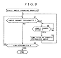
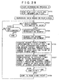
- Fig. 8 Described below with reference to the flowchart of Fig. 8 is an angle changing process. This is a basic process by which to change multiple angles seamlessly during reproduction.
- step S1 the control unit 23 determines whether the user has given an instruction to change the angle currently used for reproduction with another angle. If in step S1 the instruction to change angles is found given, step S2 is reached. In step S2, the control unit 23 determines whether the current reproducing location is at an angle change point.
- step S2 If in step S2 the current location is not found to be at an angle change point, step S2 is repeated until the current location is found to have reached an angle change point.
- step S3 is reached.
- the control unit 23 causes the reproducing location to jump to an AV stream head defined by the play items of the designated angle. The AV stream data is then reproduced.
- control is returned to step S1, and the subsequent steps are repeated.
- step S4 the control unit 23 determines whether the user has given an instruction to end reproduction. If in step S4 the instruction to end reproduction is not found given, step S1 is reached again and the subsequent steps are repeated. If the instruction to end reproduction is detected in step S4, this process is terminated.
- the clip information file of each clip provides information representing the start and end addresses of each of the play items for jumps to be made to the AV stream heads, as well as data size (in bytes) information.
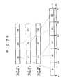
- Fig. 9 schematically illustrates data content of clip information files.
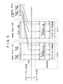
- the video stream data in each of the AV stream data A1, B1 and C1 starts with a closed GOP headed by a sequence header.
- the same timestamp T1 is given to each of the AV stream data A1, B1 and C1 which start being displayed for the same display period (T1 - T2).
- the closed GOP refers to a group of pictures that are encoded so as to conclude within one segment (e.g., reproduction segments a1, b1 and c1).
- the GOP does not apply if the pictures involved are encoded so as to conclude within each segment, i.e., if there exists no predictive relation between one segment (e.g., reproduction segment a1) and any other segment (e.g., reproduction segment b1).
- the video stream data in each of the AV stream data A2, B2 and C2 starts with a closed GOP headed by a sequence header.
- the same timestamp T2 is given to each of the AV stream data A2, B2 and C2 which start being displayed for the same display period (T2 - T3).
- the video stream data in each of the AV stream data A3, B3 and C3 also starts with a closed GOP headed by a sequence header.
- the same timestamp T3 is given to each of the AV stream data A3, B3 and C3 which start being displayed for the same display period (T3 - T4).
- the video stream data in each of all AV stream data A1, B1, C1, A2, B2, C2, A3, B3 and C3 starts with a closed GOP in which the first picture to be displayed is an I picture.
- the audio stream data in the AV stream data A1, B1 and C1 is the same, and so is the audio stream data in the AV stream data A2, B2 and C2. Furthermore, the audio stream data in the AV stream data A3, B3 and C3 is the same as well.
- Each of the AV stream data A1, B1 and C1 includes video and audio packets.
- the first packet is always a video packet in each of the AV stream data A1, B1 and C1.
- the payload of the first video packet begins with an I picture headed by a sequence header and a GOP header.
- the first packet is a video packet in each of the AV stream data A2, B2 and C2; the payload of the first video packet begins with an I picture headed by a sequence header and a GOP header.
- the first packet is also a video packet in each of the AV stream data A3, B3 and C3; the payload of the first video packet also begins with an I picture headed by a sequence header and a GOP header.
- each of the AV stream data A1, B1 and C1 may begin with PAT (program association table) and PMT (program map table) followed by video packets of the first elementary stream that comes behind.
- PAT program association table
- PMT program map table
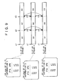
- the clip information file has a map called EP_map describing the relations of correspondence between the timestamps of entry points to clips on the one hand, and the source packet numbers of the source packets from which to start decoding streams in clip AV stream files on the other hand.
- the source packet number refers to a number which is incremented by 1 when given serially to each of the source packets ( Fig. 6 ) in an AV stream file. The source packet number at the beginning of the file is zero.
- EP_map of the clip information 1 about the clip AV stream 1 the payloads of the source packets identified by the numbers x1, x2 and x3 are shown starting with I pictures having display start timestamps of T1, T2 and T3 respectively.
- EP_map of the clip information 2 about the clip AV stream 2 the payloads of the source packets identified by the numbers y1, y2 and y3 are shown starting with I pictures also having the display start timestamps of T1, T2 and T3 respectively.
- EP_map of the clip information 3 about the clip AV stream 3 the payloads of the source packets identified by the numbers z1, z2 and z3 are shown starting with I pictures having the display start timestamps of T1, T2 and T3 respectively as well.
- the payloads of the source packets identified by the numbers x1, y1 and z1 each start with the I picture having the display start timestamp of T1; the payloads of the source packets identified by the numbers x2, y2 and z2 each start with the I picture having the display start timestamp of T2; and the payloads of the source packets identified by the numbers x3, y3 and z3 each start with the I picture having the display start timestamp of T3.
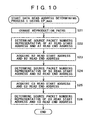
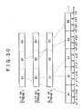
- angles are changed during reproduction over the reproduction segment a1 defined by the first play item of the angle #1, over the reproduction segment a2 defined by the second play item of the angle #2, and over the reproduction segment a3 defined by the third play item of the angle #3.
- step S21 reproduction paths are changed. More specifically, the control unit 23 acquires from EP_map of the clip 1 the read start address and read end address of the AV stream data A1 in order to read the AV stream data A1 corresponding to the reproduction segment a1 defined by the first play item of the angle #1.
- step S22 the control unit 23 reads from EP_map the source packet number x1 corresponding to the timestamp T1 as the read start address of the AV stream data A1 and the source packet number x2 corresponding to the timestamp T2 as the read end address of the AV stream data A1, and determines the source packet number (x2-1) immediately preceding the source packet number x2.
- step S23 the control unit 23 acquires from EP_map of the clip 2 the read start address T2 and read end address T3 of the AV stream data B2 in order to read the AV stream data B2 corresponding to the reproduction segment b2 defined by the second play item of the angle #2.
- step S24 the control unit 23 determines the source packet number y2 corresponding to the timestamp T2 as the read start address of the AV stream data B2, and the source packet number (y3-1) immediately preceding the source packet number y3 corresponding to the timestamp T3 as the read end address of the AV stream data B2.
- step S25 the control unit 23 acquires from EP_map of the clip 3 the read start address T3 and read end address T4 of the AV stream data C3 in order to read the AV stream data C3 corresponding to the reproduction segment c3 defined by the third play item of the angle #3.
- step S26 the control unit 23 determines the source packet number z3 corresponding to the timestamp T3 as the read start address of the AV stream data C3, and the last source packet number of the clip 3 as the read end address of the AV stream data C3. This terminates the process of Fig. 10 .
- the data read addresses are determined using EP_map, and the reproduction segments defined by the play items are reproduced accordingly.
- a plurality of clips are multiplexed and recorded will now be described with reference to Fig. 11 .
- the AV stream data of the angles involved may be interleaved in increments of an angle change unit (the smallest increment in which angles can be changed), such as A1, B1, C1, A2, B2, C2, A3, B3 and C3. This arrangement minimizes the jump time required for an angle change per play item.
- Described below with reference to Fig. 12 is another method whereby a plurality of clips are multiplexed and recorded.
- the AV stream data of the angles involved may be interleaved in increments of a plurality of (e.g., three) consecutive angle change units (e.g., A1, A2 and A3 as a group; B1, B2 and B3 as another group; and C1, C2 and C3 as yet another group out of A1, B1, C1, A2, B2, C2, A3, B3 and C3).
- a plurality of consecutive angle change units e.g., A1, A2 and A3 as a group; B1, B2 and B3 as another group; and C1, C2 and C3 as yet another group out of A1, B1, C1, A2, B2, C2, A3, B3 and C3.
- the addresses of the angle change points (e.g., source packet numbers x1, x2, x3, etc., corresponding to the timestamps T1, T2, T3, etc., as the read start addresses of the AV stream data A1, A2, A3, etc., in Fig. 13 ) are acquired from EP_map of each AV stream as in the case of Fig. 9 .
- each group of consecutive angle change units constitutes an ILVU (interleaved unit)
- the jump time required for an angle change from one play item to another is longer than in the example of Fig. 11
- the amount of management data in the segmented file data is made smaller than in the earlier example.
- the amount of management data in the segmented file data is about one third of the amount required in the example of Fig. 11 .
- the user may choose one of the two recording methods above for multiplexing the clips to be recorded as shown in Figs. 11 and 12 .
- the choice depends on the priority being given either to the access speed of the drive reproducing data from the recording medium 100 or to the amount of management data in the file data.
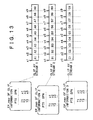
- each EP_map all entry points contained in each EP_map are angle change points. If the entry points in any EP_map include those that are not angle change points, that EP_map may record flags indicating whether or not each of the entry points therein is an angle change point, as illustrated in Fig. 14 .
- each of the entry points in EP_map for the clip information 1 corresponding to the clip 1 has field data made up of "is_AngleChange_point,” “PTS_EP_start,” and "SPN_EP_start.”
- the field data "is_AngleChange_point” indicates whether angles can be changed at the entry point in question.
- the field data "SPN_EP_start” denotes the packet number corresponding to that entry point.
- the data field “PTS_EP_start” represents the display start time of the entry point.
- angles can be changed at the entry points whose "SPN_EP_start” is x1, x2 or x3.
- the data “is_AngleChange_point” is “1” for each of these entry points.
- angles cannot be changed at the entry points whose "SPN_EP_start” is x11 or x12.
- “is_AngleChange_point” is "0” for each entry point.
- the field data “is_AngleChange_point” being set to "0” signifies that seamless angle change is not guaranteed at the entry point in question, i.e., that AV stream data may or may not be supplied continuously at a required bit rate.
- AV stream data recorded in interleaved fashion as shown in Fig. 12 is to be reproduced with angles changed.
- the addresses of angle change points e.g., source packet numbers x1, x2, x3, etc., corresponding to timestamps T1, T2, T3, etc., as the read start addresses of AV stream data A1, A2, A3, etc., in Fig. 14
- EP_map of each AV stream as depicted in Fig. 14 , as well as in Fig. 9 as discussed earlier.
- the user may choose in advance the number of consecutive angle change units (each being the smallest increment in which angles can be changed). The choice depends on the priority being given either to the access speed of the drive reproducing data from the recording medium 100 or to the amount of management data in the file data.
- the number of consecutive angle change units for three angles is 1.
- the number of consecutive angle change units for three angles is 3.
- the range of numbers M of consecutive angle change units for allowing data to be reproduced without interruption is determined by a number of factors: the time required for a jump over a predetermined distance for reproduction, the speed at which to read data from such jumps, the rate for AV streams to be recorded, and the number of angles involved.
- the capability of the reading unit 28 as part of the reproduction unit 3 in the recording/reproducing apparatus 1 determines relations between jump distances for continuously reproducing discontinuous cells on the one hand, and the jumps times required to execute such jumps on the other hand.
- the memory 34 retains a table of jump times associated with jump distances.
- the control unit 23 references that table in the memory 34 when determining an appropriate recording method.
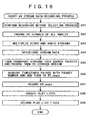
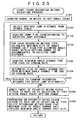
- step S41 a recording method selecting process, to be described later with reference to Fig. 17 , is carried out.
- step S42 the AV encoder 15 encodes video signals of the segments involved into a video stream starting with a closed GOP, and encodes audio signals of the segments into an audio stream. The encoding process is performed on the video and audio signals for all angles in keeping with the parameters designated by the recording method selected by the recording method selecting process in step S41.
- step S43 the multiplexer 16 multiplexes the video and audio streams of the segments involved into a transport stream per segment.
- the AV stream data for each angle is interleaved according to the data layout designated by the recording method selected by the recording method selecting process in step S41.
- the multiplexer 16 performs its multiplexing process in such a manner that the first packet is always a video packet starting with an I picture of a closed GOP.
- step S45 the source packetizer 19 turns the transport stream of each segment into source packets.
- the writing unit 22 records the source packets to the recording medium 100 as AV stream files. This is how multi-angle clip AV stream files formed by the transport streams composed of the recorded source packets are created on the recording medium 100.
- the packet ID (PID) is the same for the video packets in the transport streams, and the packet ID is also the same for the audio packets in the transport streams.
- step S46 the multiplexed stream analysis unit 18 acquires the timestamp of the I picture heading the transport stream per segment, and the packet number of the packet whose packetload starts with an I picture in the transport stream.
- the control unit 23 adds the acquired pair of the timestamp and packet number to EP_map (if EP_map does not exist, it is created).
- step S47 the control unit 23 causes the writing unit 22 to record EP_map created for each of the clip AV stream files to a predetermined area on the recording medium 100 in concentrated fashion.
- step S48 the control unit 23 creates play lists.
- step S49 the control unit 23 causes the writing unit 22 to record play list files having data structures representing each of the segments in play item form, to a predetermined area on the recording medium 100 in concentrated fashion. If, as shown in Fig. 14 , the entry points placed in EP_map include those that are not angle change points, then the angle change points are established on the basis of the flags in EP_map (each flag is either "1" or "0") when the control unit 23 creates play lists in step S48. This is how AV stream data for multi-angle use is recorded to the recording medium 100.
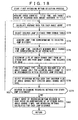
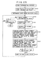
- step S61 the control unit 23 determines whether or not to select an angle change time with an angle count, a title time, and a recorded data amount all fixed.
- step S61 If in step S61 the angle change time is found to be selected with the angle count, title time, and recorded data amount fixed, step S62 is reached.
- step S62 a first recording method selecting process, to be discussed later with reference to Fig. 18 , is performed.
- control is passed on to step S42 in Fig. 16 .
- step S63 determines whether or not to select the recording method with priority given to the rate.
- step S63 If in step S63 the recording method is found to be selected with priority given to the rate, then step S64 is reached.
- step S64 a second recording method selecting process, to be described later with reference to Fig. 21 , is carried out. At the end of the process in step S64, control is passed on to step S42 in Fig. 16 .
- step S63 If in step S63 the recording method is not found to be selected with priority given to the rate, then a recording method with the priority given to the angle count is selected. That is, step S65 is reached and a third recording method selecting process, to be discussed later with reference to Fig. 23 , is executed. At the end of the process in step S65, control is passed on to step S42 in Fig. 16 .
- one of a plurality of recording method selecting processes is selected as desired by the user whose operation input is supplied through the terminal 24.
- Type A is a method whereby the number M of consecutive angle change units per ILVU is set to 1
- type B is a method whereby the number M of consecutive angle change units per ILVU is set to 2
- type C is a method whereby the number M of consecutive angle change units per ILVU is set to 4. If the selected data recording method is type A, one angle change unit is found per ILVU. In this case, data is recorded in the following order: A1, B1, C1, A2, B2, C2, A3, B3, C3, etc. If the selected data recording method is type B, two angle change units are furnished per ILVU.
- Data is then recorded in the order of A1, A2, B1, B2, C1, C2, A3, A4, B3, B4, etc. If the selected data recording method is type C, four angle change units are provided per ILVU. In that case, data is recorded in the following order: A1, A2, A3, A4, B11, B2, B3, B4, C1, C2, C3, C4, etc.
- step S71 the control unit 23 acquires an angle count or counts, a title time required for the title to be recorded (i.e., AV data 1), and a target value of the recorded data amount assigned to the title.
- step S72 the control unit 23 calculates an average rate for one or a plurality of angle counts selected, on the basis of what was acquired in step S71: the angle count or counts, the time for the title to be recorded, and the target value of the recorded data amount assigned to the title.
- step S73 the control unit 23 selects an appropriate jump distance "j" from the table held in the memory 34 in accordance with the user's operation input from the terminal 24.
- step S74 the control unit 23 references the memory 34 to acquire a jump time T acc corresponding to the jump distance "j" selected in step S73. It is assumed here that the table in the memory 34 retains jump times T acc corresponding to the jump distances "j" over 5,000 sectors, 20,000 sectors, and 40,000 sectors.
- step S75 from the jump time acquired in step S74, the control unit 23 calculates a minimum angle change time "t" corresponding to an AV stream rate R max which is at least equal to the average rate R ave .
- the AV stream rate R max is 10 ⁇ 10 6 (bps), 20 ⁇ 10 6 (bps), 30 ⁇ 10 6 (bps), or 40 ⁇ 10 6 (bps).
- step S76 the control unit 23 acquires an angle change time T c desired by the user whose operation input is supplied through the terminal 24. From the AV stream rate and the angle change time T c desired by the user, the control unit 23 determines an angle change unit size U size using the expression (4) shown below. The angle change time T c must be longer than the minimum angle change time "t.” If the angle change time T c desired by the user is found shorter than the minimum angle change time "t,” then the angle change unit size U size will not be calculated.
- step S77 the control unit 23 calculates, for each of angle count types A through C, a maximum size U max of the angle change unit for allowing each angle count N to be accommodated within the selected jump distance using the expression (5) below:
- U max j / 2 ⁇ N - 2 ⁇ M
- step S78 the control unit 23 selects the recording method such that the maximum size U max of the angle change unit exceeds the angle change unit size U size .
- the calculated maximum size U max of the angle change unit is compared with the angle change unit size U size for each candidate recording method.
- the recording method whereby the calculated maximum size U max of the angle change unit is greater than the angle change unit size U size is then selected as a usable recording method.
- step S79 according to the user's operation input from the terminal 24, the control unit 23 determines whether or not to examine the recording methods for any jump distance other than the distance selected in step S73. If in step S79 the recording methods are found desired to be examined for any other jump distance, step S73 is reached again and the subsequent steps are repeated on that jump distance.
- step S80 the control unit 23 presents the user with information about the combinations of the calculated AV stream rates, angle change times, and recording methods for each of the jump distances involved.
- the information is output through the terminal 24 and displayed illustratively on a suitable display device so that the user may verify what is displayed before selecting an appropriate recording method.
- the control unit 23 admits the input of the recording method desired by the user through the terminal 24. Control is then passed on to step S42 of Fig. 16 .
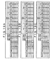
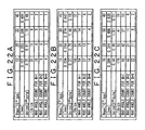
- Figs. 19A, 19B and 19C Typical results of the calculations above are explained below with reference to Figs. 19A, 19B and 19C . These figures indicate some results of the calculations performed with the data read rate R ud set for 54 Mbps.
- Fig. 19A is an explanatory view of representative results of the calculations performed on the jump distance of 5,000 sectors selected in step S73, with the jump time T acc set for 0.128 seconds.
- Fig. 19B is an explanatory view of typical results of the calculations carried out on the jump distance of 20,000 sectors selected in step S73, with the jump time T acc set for 0.166 seconds.
- Fig. 19C is an explanatory view of what has resulted from the calculations executed on the jump distance of 40,000 sectors selected in step S73, with the jump time T acc set for 0.217 seconds.
- the maximum size U max of the angle change size is compared with the angle change unit size U size for each of the candidate recording methods.
- the recording method whereby the calculated maximum size U max of the angle change unit is greater than the angle change unit size U size is then selected as a usable recording method. More particularly, the recording methods marked "OK" in Figs. 19A through 19C are selected as usable methods.
- the amount of information for managing data layout can be reduced by raising the number of consecutive angle change units.
- the amount of information for managing data layout increases in proportion to the number of data items.
- An increase in the time required for recording the title translates into a larger number of data items, so that the amount of information for managing data layout is also raised.
- suitable arrangements may be implemented to automatically select the recording method where the number of consecutive angle change units is maximized, or to prompt the user to choose that recording method.
- step S91 the control unit 23 acquires a target value R max of the AV stream rate in keeping with the user's operation input from the terminal 24.
- step S92 the control unit 23 selects an appropriate jump distance "j" from a table in the memory 34 according to the user's operation input from the terminal 24.
- step S93 the control unit 23 references the memory 34 to acquire a jump time T acc corresponding to the jump distance selected in step S92. It is assumed that the table in the memory 34 contains jump times T acc corresponding to the jump distances of 5,000 sectors, 20,000 sectors, and 40,000 sectors.
- step S94 the control unit 23 calculates a minimum angle change time "t" corresponding to the target value R max of the AV stream rate from the jump time T acc acquired in step S93 and from the data read rate R ud of the recording/reproducing apparatus 1.
- the minimum angle change time "t” is calculated by use of the expression (3) shown above.
- step S96 the control unit 23 calculates the number of minimum angle change units within the jump distance selected in step S92, from the minimum angle change unit size U size computed in step S95.
- step S97 the control unit 23 examines a recordable angle count N for each of the minimum angle change units within the jump distance calculated in step S96.
- the number of angle change units that should go into the jump distance is given as (2N - 2)M, where N stands for the number of angles and M denotes the number of consecutive angle change units for the same angle.
- the number M of consecutive angle change units is 1, 2 and 4 for the recording method types A, B and C respectively. Therefore, a maximum usable angle count N is a value that will not exceed what is obtained by dividing the jump distance selected in step S92 by the minimum angle change unit size U size (obtained in step S96).
- step S98 based on the user's operation input from the terminal 24, the control unit 23 determines whether or not to examine the recording methods for any jump distance other than the distance selected in step S92. If in step S98 the recording methods are found desired to be examined for any other jump distance, step S92 is reached again and the subsequent steps are repeated on that jump distance.
- step S98 the recording methods are not found desired to be examined for any jump distance other than the distance selected in step S92, then step S99 is reached.
- the control unit 23 selects the method whereby the largest number of data items can be recorded consecutively for the same angle as long as the necessary angle count N for recording data as desired by the user is provided and the process goes on to step S42.
- Typical results of the calculations carried out by the second recording method selecting process above are shown in Figs. 22A, 22B and 22C . As with the first process, these figures indicate results of the calculations performed with the data read rate R ud set for 54 Mbps.
- Fig. 22A is an explanatory view of representative results of the calculations performed on the jump distance of 5,000 sectors selected in step S92, with the jump time T acc set for 0.128 seconds.
- Fig. 22B is an explanatory view of typical results of the calculations carried out on the jump distance of 20,000 sectors selected in step S92, with the jump time T acc set for 0.166 seconds.
- Fig. 22C is an explanatory view of what has resulted from the calculations executed on the jump distance of 40,000 sectors selected in step S92, with the jump time T acc set for 0.217 seconds.
- the target value R max of the AV stream rate acquired in step S91 is 10 ⁇ 10 6 (bps) and that the jump distance selected in step S92 is 5,000 sectors.
- the minimum angle change time "t" is calculated at 0.157 seconds using the expression (3) and the minimum angle change unit size U size at 0.31 (2 20 bytes) using the expression (6).
- the same calculations also apply if the jump distance selected in step S92 is 20,000 sectors and if the jump time T acc is 0.166 seconds.
- the results of the calculations are indicated in Fig. 22B .
- the number M of consecutive angle change units for the recording method to be selected is 1.
- the number M of consecutive angle change units for the recording method to be selected is 2.
- the same calculations also apply when the jump distance selected in step S92 is 40,000 sectors, with the results of the calculations shown in Fig. 22C .
- the number M of consecutive angle change units for the recording method to be selected is 2. If the user sets the target value R max of the AV stream rate for 20 ⁇ 10 6 (bps) and decides to need 10 angles, then the number M of consecutive angle change units for the recording method to be selected is 4.
- step S101 the control unit 23 acquires the range in which to set the number of angles on the basis of the user's operation input coming from the terminal 24.
- step S102 according to the user's operation input from the terminal 24, the control unit 23 selects the desired jump distance "j" from a table in the memory 34.
- step S103 the control unit 23 references the memory 34 to acquire a jump time T acc corresponding to the jump distance selected in step S102. It is also assumed here that the table in the memory 34 contains jump times T acc corresponding to the jump distances of 5,000 sectors, 20,000 sectors, and 40,000 sectors.
- step S104 the control unit 23 calculates a maximum size U max of the angle change unit for allowing the angle count within the acquired setting range to be accommodated in the selected jump distance for each of recording method types A through C, using the expression (7) below:
- U max j / 2 ⁇ N - 2 ⁇ M
- step S105 the control unit 23 acquires the minimum angle change time "t" for each AV stream rate R max using the expression (3) given above.
- step S106 the control unit 23 determines the angle change unit size U size from the minimum angle change time "t" calculated in step S105 and from the AV stream rate R max , by use of the expression (6) indicated above.
- step S107 according to the user's operation input from the terminal 24, the control unit 23 determines whether or not to examine the recording methods for any jump distance other than the distance selected in step S102. If in step S107 the recording methods are found desired to be examined for any other jump distance, step S102 is reached again and the subsequent steps are repeated on that jump distance.
- step S108 is reached.
- the control unit 23 admits the input of the priority being given either to the rate, or to the selection of the method type within the angle count setting range, i.e., to the number of consecutive angle change units.
- step S109 depending on the priority given to the rate or to the selection of the method type, the control unit 23 selects the best recording method such that the maximum size U max of the angle change unit exceeds the minimum angle change unit size U size . Control is then passed on to step S42 of Fig. 16 .
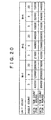
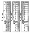
- Figs. 24A, 24B and 24C Typical results of the calculations carried out by the third recording method selecting process above are shown in Figs. 24A, 24B and 24C.
- Fig. 24A is an explanatory view of representative results of the calculations performed on the jump distance of 5,000 sectors selected in step S102, with the jump time T acc set for 0.128 seconds.
- Fig. 24B is an explanatory view of typical results of the calculations carried out on the jump distance of 20,000 sectors selected in step S102, with the jump time T acc set for 0.166 seconds.
- Fig. 24C is an explanatory view of what has resulted from the calculations executed on the jump distance of 40,000 sectors selected in step S102, with the jump time T acc set for 0.217 seconds.
- the angle change unit size U size is calculated from the minimum angle change time "t" computed in step S105 and from the AV stream rate R max , using the expression (6) above.
- the angle change unit size U size is calculated at 0.312 (2 20 bytes) with the AV stream rate R max set for 10 ⁇ 10 6 (bps); the angle change unit size U size is calculated at 0.610 (2 20 bytes) with the AV stream rate R max set for 20 ⁇ 10 6 (bps); the angle change unit size U size is calculated at 1.155 (2 20 bytes) with the AV stream rate R max set for 30 ⁇ 10 6 (bps); and the angle change unit size U size is calculated at 2.479 (2 20 bytes) with the AV stream rate R max set for 40 ⁇ 10 6 (bps), as indicated in Fig. 24A .
- the angle change unit size U size is calculated at 0.368 (2 20 bytes) with the AV stream rate R max set for 10 ⁇ 10 6 (bps); the angle change unit size U size is calculated at 0.754 (2 20 bytes) with the AV stream rate R max set for 20 ⁇ 10 6 (bps); the angle change unit size U size is calculated at 1.461 (2 20 bytes) with the AV stream rate R max set for 30 ⁇ 10 6 (bps); and the angle change unit size U size is calculated at 3.178 (2 20 bytes) with the AV stream rate R max set for 40 ⁇ 10 6 (bps), as shown in Fig. 24B .
- the angle change unit size U size is calculated at 0.125 (2 20 bytes) with the AV stream rate R max set for 10 ⁇ 10 6 (bps); the angle change unit size U size is calculated at 0.945 (2 20 bytes) with the AV stream rate R max set for 20 ⁇ 10 6 (bps); the angle change unit size U size is calculated at 1.868 (2 20 bytes) with the AV stream rate R max set for 30 ⁇ 10 6 (bps); and the angle change unit size U size is calculated at 4.110 (2 20 bytes) with the AV stream rate R max set for 40 ⁇ 10 6 (bps), as shown in Fig. 24C .
- a mark "OK” is attached to each recording method whereby the maximum size U max of the angle change unit is equal to or greater than the minimum angle change unit size U size ; and a mark "NG” is given to the recording methods whereby the maximum size U max of the angle change unit does not exceed the minimum angle change unit size U size .
- the angle count setting range is found to include a count of 3 in step S101 and that the jump distance selected in step S102 is 5,000 sectors only.
- the AV stream rate R max of 30 ⁇ 10 6 (bps) is selected if the priority is given to the rate in step S108 and if the number M of consecutive angle change units is set for 2; or the AV stream rate R max of 20 ⁇ 10 6 (bps) is selected if the priority is given in step S108 to the selection of the recording method type (i.e., number of consecutive angle change units) and if the number M of consecutive angle change units is set for 4.
- the AV stream rate R max of 40 ⁇ 10 6 (bps) is selected with the priority given to the rate in step S10B and with the number M of consecutive angle change units set for 2; or the AV stream rate R max of 30 ⁇ 10 6 (bps) is selected with the priority given in step S108 to the selection of the recording method type and with the number M of consecutive angle change units set for 4. If the jump distance of 40,000 is further selected in step S102, then the AV stream rate R max of 40 ⁇ 10 6 (bps) is selected with the number M of consecutive angle change units set for 4, regardless of the priority being given to the rate or to the selection of the recording method type in step S108.
- step S101 the angle count setting range is set for 9 or larger in step S101 and that the jump distance of 5,000 sectors only is selected in step S102.
- the AV stream rate R max of 20 ⁇ 10 6 (bps) is selected with the number M of consecutive angle change units set for 1, regardless of the priority being given to the rate or to the selection of the recording method type in step S108.
- the AV stream rate R max of 30 ⁇ 10 6 (bps) is selected with the priority given to the rate in step S108 and with the number M of consecutive angle change units set for 1; or the AV stream rate R max of 10 ⁇ 10 6 (bps) is selected with the priority given to the selection of the recording method type in step S108 and with the number M of consecutive angle change units set for 4.
- the AV stream rate R max of 40 ⁇ 10 6 (bps) is selected with the priority given to the rate in step S108 and with the number M of consecutive angle change units set for 1; or the AV stream rate R max of 20 ⁇ 10 6 (bps) is selected with the priority given to the selection of the recording method type in step S108 and with the number M of consecutive angle change units set for 4.
- step S101 If the angle count setting range is set for 20 or larger in step S101 and if the jump distance of 5,000 sectors only is selected in step S102, then there is no selectable recording method. If the jump distance of 20,000 sectors is selected in step S102, the AV stream rate R max of 20 ⁇ 10 6 (bps) is selected with the priority given to the rate in step S108 and with the number M of consecutive angle change units set for 1; or the AV stream rate R max of 10 ⁇ 10 6 (bps) is selected with the priority given to the selection of the recording method type in step S108 and with the number M of consecutive angle change units set for 2.
- the AV stream rate R max of 30 ⁇ 10 6 (bps) is selected with the priority given to the rate in step S108 and with the number M of consecutive angle change units set for 1; or the AV stream rate R max of 10 ⁇ 10 6 (bps) is selected with the priority given to the selection of the recording method type in step S108 and with the number M of consecutive angle change units set for 4.
- the processes for recording AV stream data may be implemented not only by apparatuses capable of both recording and reproducing data such as the recording/reproducing apparatus 1 in Fig. 4 but also by apparatuses only for recording data.
- the memory 34 was shown holding the table specifying the relations between jump distances and jump times in effect during data reproduction, with the control unit 23 referencing the table in selecting recording methods.
- this is not limitative of the invention.
- information designating the relations between jump distances and jump times for data reproduction can obviously be input just as effectively from an external source.
- step S121 the control unit 23 reads from the recording medium 100 all play list files for multi-angle use and the clip information files (including EP_map) of the clips referenced by each of the play lists. This step constitutes a look-ahead operation. Because the EP_map data items are recorded in concentrated fashion, they can be retrieved at high speed.
- step S122 the control unit 23 reproduces AV stream data successively starting from the location identified by the first play item in accordance with the play lists read in step S121.
- step S123 the control unit 23 determines whether the user has designated an angle change through the user interface 24.
- step S124 the control unit 23 searches the play list corresponding to the change-source (i.e., currently reproduced) angle for a first play item having the future display end time closest to the current reproduction time. For example, if a change is designated to occur from angle #1 to angle #2 between the timestamps T1 and T2, then the play item a1 is the first play item in question.
- the change-source i.e., currently reproduced
- step S125 the control unit 23 searches the play list corresponding to the change-destination angle for a second play item having as its display start time the display end time of the first play item above. If a change is designated to occur from angle #1 to angle #2 between the timestamps T1 and T2 in the example of Fig. 7 , then the play item a2 is the second play item in question.
- step S126 the control unit 23 acquires the source packet number corresponding to the display end time of the first play item by looking up EP_map of the clip referenced by the first play item, and regards the source packet immediately preceding the acquired source packet number as the data read end point of the change-source angle.
- step S127 the control unit 23 acquires the source packet number corresponding to the display start time of the second play item by looking up EP_map of the clip referenced by the second play item, and regards the source packet of the acquired source packet number as the data read start point of the change-destination angle.
- step S128 the control unit 23 determines whether the current location has reached the end point calculated in step S126. If the current location is not found to have reached the end point, the control unit 23 waits for the end point to be reached. When the end point is found reached, control is transferred to step S129. In step S129, the control unit 23 causes the reproducing location to jump to the start point calculated in step S127. Step S123 is then reached again and the subsequent steps are repeated.
- step S130 the control unit 23 determines whether the user designated an end of the ongoing reproduction. If in step S130 an end is not found designated, then step S123 is reached again and the process is repeated. If in step S130 an end of the reproduction is found designated, the reproducing process is terminated.
- Fig. 26 schematically shows another typical structure of a play list for multi-angle use.
- a single multi-angle play list contains a single play item.
- the play item illustratively has two items of information.
- the first item is information (designation information) about the AV streams to be referenced as destinations for multi-angle reproduction.
- the first item of information designates angles #1, f2 and #3 referencing clip AV streams 1, 2 and 3 as their destinations respectively.
- the designation information points to these destinations (i.e., it serves as pointers).
- the second item of information is made up of an in-point (IN_time) and an out-point (OUT_time) delimiting the time segment for multi-angle reproduction.
- In_time is T1 and Out_time is T4.
- the entry point times representing the angle change points in a given time segment for multi-angle reproduction can be acquired from EP_map of the database (i.e., clip) furnished to the clip AV stream referenced by the first item of information. These entry point times are T2 and T3 in the case of Fig. 26 .
- the structure of EP_map used here is the same as that described earlier with reference to Fig. 14 .
- the entry point times indicative of the angle change points may be acquired from "PTS_EP_start" values of the entries for which "is_AngleChange_point" is "1" in EP_map.
- Fig. 27 shows a syntax of the play item indicated in Fig. 26 .
- "Clip_information_file_name” indicates the AV streams as the destinations to be referenced for use in multi-angle reproduction.
- In_time and OUT_time delimit the time segment for multi-angle reproduction.
- three EP_maps explained with reference to Fig. 14 can be utilized unmodified for conversion from times to data addresses.
- Steps S151 through S160 are basically the same as steps S121 through 130 in Fig. 25 .
- the control unit 23 detects not the first play item but a first reproduction segment in the play item.
- the control unit 23 detects not the second play item but a second reproduction segment in the play item. If an angle change is designated to occur from angle #1 to angle #2 between the timestamps T1 and T2 in the example of Fig. 26 , the first and the second reproduction segments are the segments a1 and b2.
- step S156 the control unit 23 acquires the source packet number corresponding to the display end time of the segment corresponding to the first reproduction segment by looking up EP_map of the clip referenced by the segment corresponding to the first reproduction segment.
- step S157 the control unit 23 acquires the source packet number corresponding to the display start time of the segment corresponding to the second reproduction segment by looking up EP_map of the clip referenced by the segment corresponding to the second reproduction segment.
- Fig. 29 schematically depicts another structure of the AV stream file.
- the clip AV streams 1, 2, and 3 are each furnished with EP_map (in the case of Fig. 9 , EP_map of the clip information 1 is provided to the clip AV stream 1, EP_map of the clip information 2 to the clip AV stream 2, and EP_map of the clip information 3 to the clip AV stream 3).
- EP_map of the clip information 1 is provided to the clip AV stream 1, EP_map of the clip information 2 to the clip AV stream 2, and EP_map of the clip information 3 to the clip AV stream 3.
- one EP_map is shown furnished illustratively to three clip AV streams (i.e., clip AV streams 1, 2, and 3).
- the AV stream file is interleaved in the order of AV stream data A1, B1, C1, A2, B2, C2, A3, B3 and C3.
- Source packet numbers are assigned serially to the source packets in the AV stream file of each of the clip AV streams (i.e., clip AV streams 1, 2, and 3; in the example of Fig. 29 , the assigned source packet numbers are x1, y1, z1, x2, y2, z2, x3, y3 and z3.).
- Fig. 29 at least two GOP's may be included in the video stream data in each of the AV stream data A1, B1, C1, A2, B2, C2, A3, B3, and C3.
- the second and subsequent GOP's need not be closed GOP's (i.e., they may be unclosed GOP's).
- it is mandatory that encoding be complete within each AV streams data item (e.g., in the AV stream data A1).
- the video stream data in the AV stream data A1 includes one closed GOP and two unclosed GOP's.
- the source packet numbers are provided illustratively as x1, x11, and x12 in the AV stream file.
- the source packets having the source packet numbers x11 and x12 correspond to the two unclosed GOP's.
- the video stream data in the AV stream data B1 also includes on closed GOP and two unclosed GOP's.
- the source packet numbers are provided illustratively as y1, y11, and y12 in the AV stream file.
- the source packets with the source packet numbers y11 and y12 correspond to the two unclosed GOP's.
- the video stream data in the AV stream data C1 includes one closed GOP and two unclosed GOP's.
- the source packet numbers are provided illustratively as z1, z11, and z12 in the AV stream file.
- the source packets with the source packet numbers z11 and z12 correspond to the two unclosed GOP's.
- Fig. 31 schematically shows data content of a clip information file included in Fig. 30 .
- the content of the AV stream data A1, B1, C1, A2, B2, C2, A3, B3, and C3 is basically the same as what is shown in Fig. 9 and thus will not be discussed further.
- the clip information file furnished to an AV stream file (clip AV stream file X) has EP_map that describes the relations of correspondence between the timestamps of the entry points in the clip on the one hand, and the source packet numbers from which to start decoding the stream in the clip AV stream file on the other hand.
- Each of the entry points in EP_map has field data "is_AngleChange_point,” “Angle_number,” “PTS_EP_start,” and “SPN_EP_start.”
- the data “is_AngleChange_point” indicates whether angles can be changed at the entry point in question.
- the data “Angle_number,” as its name implies, indicates the angle number of the angle to which the entry point in question belongs.
- the data “SPN_EP_start” indicates the packet number of the entry point in question.
- the data “PTS_EP_start” indicates the display start time of the entry point in question.
- the entry points with their "SPN_EP_start” set for x1, x2 or x3 are points where angles can be changed, so that these points have their data “is_AngleChange_point” set for "1.”
- the entry points with their "SPN_EP_start” set for x11 or x12 are points where angles cannot be changed so that these points have their data “is_AngleChange_point” set for "1.”
- the data "is_AngleChange_point” signifies that seamless change is not guaranteed even if attempted at an entry point where the data is set for "0,” i.e., that the AV stream data is not guaranteed to be supplied continuously at a required bit rate.
- the same also applies to the entry points with their data "SPN_EP_start” set for y11, y12, z11, or z12.
- Fig. 32 shows a syntax of a play item for use in managing the clip AV stream file in Fig. 31 .
- the data "Clip_information_file_name” stands for the reference destination of the AV stream used in multi-angle reproduction (Clip_information_X in the example of Fig. 32 ).
- the data "IN_time” (T1 in the case of Fig. 32 ) and “OUT_time” (T4 in Fig. 32 ) denote the start and the end points, respectively, of the time segment for multi-angle reproduction.
- the EP_map explained with reference to Fig. 31 is used for conversion from times to data addresses.
- Fig. 33 Described below with reference to the flowchart of Fig. 33 is a data read address determining process 2 whereby, through the use of EP_map shown in Fig. 31 , angle-changing data reproduction is allowed to proceed from the reproduction segment a1 defined by the first play item of angle #1, to the reproduction segment a2 defined by the second play item of angle #2, and to the reproduction segment a3 defined by the third play item of angle #3.
- step S181 the control unit 23 acquires the read start address and read end address of the AV stream data A1 from the entry point data with "Angle_number" set for "1" in EP_map of Fig. 31 , in order to read the AV stream data A1 in the segment corresponding to the reproduction segment a1 defined by the first play item of angle #1.
- step S182 the control unit 23 reads from EP_map the source packet number x1 corresponding to the timestamp T1 as the read start address of the AV stream data A1, reads the source packet number y1 corresponding to the timestamp T1 with "Angle_number" set for "2" as the read end address of the AV stream data A1, and determines the source packet number immediately preceding the source packet number y1 (i.e., y1 - 1, or x12 in this particular case).
- step S183 the control unit 23 acquires the read start address and read end address of the AV stream data B2 from the entry point data with "Angle_number" set for "2" in EP_map of Fig. 31 , in order to read the AV stream data B2 in the segment corresponding to the reproduction segment b2 defined by the second play item of angle #2.
- step S184 the control unit 23 reads from EP_map the source packet number y2 corresponding to the timestamp T2 as the read start address of the AV stream data B2, reads the source packet number z2 corresponding to the timestamp T2 with "Angle_number" set for "3" as the read end address of the AV stream data B2, and determines the source packet number immediately preceding the source packet number z2 (i.e., z2 - 1, or y22 in this case).
- step S185 the control unit 23 acquires the read start address and read end address of the AV stream data C3 from the entry point data with "Angle_number” set for "3" in EP_map of Fig. 31 , in order to read the AV stream data C3 in the segment corresponding to the reproduction segment c3 defined by the third play item of angle #3.
- step S186 the control unit 23 reads from EP_map the source packet number z3 corresponding to the timestamp T3 as the read start address of the AV stream data C3, and determines the last source packet number with "Angle_number” set for "3" as the read end address of the AV stream data C3 (specifically the last source packet number is z32, not shown).
- the steps above allow the data read addresses to be determined using EP_map in Fig. 31 .
- the recording/reproducing apparatus 1 may be implemented illustratively in the form of a computer such as one shown in Fig. 34 .
- a CPU 131 carries out various processes in accordance with programs held in a ROM 132 or with programs loaded from a storage unit 138 into a RAM 133.
- the RAM 133 may also accommodate data needed by the CPU 131 in executing its processes.
- the CPU 131, ROM 132, and RAM 133 are interconnected via a bus 134.
- An input/output interface 135 is also connected to the bus 134.
- the input interface 135 is connected with: an input unit 136 made up of a keyboard and a mouse; an output unit 137 formed by a display unit such as CRT (cathode-ray tube) or LCD (liquid crystal display) and by speakers; the storage unit 138 typically composed of a hard disk drive; and a communication unit 139 constituted by a modem and/or a terminal adapter.
- the communication unit 139 conducts communications over networks including the Internet (not shown).
- the input/output interface 135 is connected with a drive 140 into which a storage medium such as a magnetic disk 151, an optical disk 152, a magneto-optical disk 153, or a semiconductor memory 154 may be loaded.
- a storage medium such as a magnetic disk 151, an optical disk 152, a magneto-optical disk 153, or a semiconductor memory 154 may be loaded.
- Computer programs retrieved from the loaded storage medium are installed as needed into the storage unit 138.
- the storage medium carrying the programs to be installed into the computer for execution may be a package medium constituted by the magnetic disk 151 (including floppy disks), optical disk 152 (including CD-ROM (compact disc-read only memory) and DVD (digital versatile disk)), magneto-optical disk 153 (including MD (Mini-disc)), or semiconductor memory 154; or may be offered in the form of the ROM 132 where the programs are stored temporarily or permanently, or hard disks constituting the storage unit 138.
- the storage medium has the programs recorded thereto as needed through wired or wireless communication means such as local area networks, the Internet, and digital satellite broadcasting networks by way of communication interfaces such as routers and modems.
- the steps which are stored on the program storage medium and which describe the programs to be executed represent not only the processes that are to be carried out in the depicted sequence (i.e., on a time series basis) but also processes that may be performed parallelly or individually.
- This invention may be applied where AV stream data is recorded to or reproduced from not only DVDs but also other optical disks such as CD-Rs, magneto-optical disks such as MDs, magnetic disks, and other recording media.
- this invention as embodied in its preferred forms was shown applied to the changing of angles in multi-angle data recording and reproduction. However, this is not limitative of the invention. Alternatively, the invention can also be adapted to the changing of reproduction paths in multi-story and rating control applications.
- the scheme according to the invention enables AV stream data to be recorded and reproduced.
- the inventive arrangements allow the user to select recording methods whereby data may be optimally laid out when recorded in such a manner as to let reproduction paths be changed seamlessly during subsequent data reproduction.
Landscapes
- Engineering & Computer Science (AREA)
- Signal Processing (AREA)
- Multimedia (AREA)
- Signal Processing For Digital Recording And Reproducing (AREA)
- Television Signal Processing For Recording (AREA)
- Management Or Editing Of Information On Record Carriers (AREA)
- Indexing, Searching, Synchronizing, And The Amount Of Synchronization Travel Of Record Carriers (AREA)
Applications Claiming Priority (2)
| Application Number | Priority Date | Filing Date | Title |
|---|---|---|---|
| JP2003119332 | 2003-04-24 | ||
| EP04724803A EP1617660B1 (fr) | 2003-04-24 | 2004-03-31 | Dispositif de traitement d'informations et procede de traitement d'informations, support de stockage de programme et programme |
Related Parent Applications (2)
| Application Number | Title | Priority Date | Filing Date |
|---|---|---|---|
| EP04724803.4 Division | 2004-03-31 | ||
| EP04724803A Division-Into EP1617660B1 (fr) | 2003-04-24 | 2004-03-31 | Dispositif de traitement d'informations et procede de traitement d'informations, support de stockage de programme et programme |
Publications (2)
| Publication Number | Publication Date |
|---|---|
| EP2265009A2 true EP2265009A2 (fr) | 2010-12-22 |
| EP2265009A3 EP2265009A3 (fr) | 2011-02-16 |
Family
ID=33308099
Family Applications (2)
| Application Number | Title | Priority Date | Filing Date |
|---|---|---|---|
| EP10011416A Withdrawn EP2265009A3 (fr) | 2003-04-24 | 2004-03-31 | Appareil de traitement d'informations, procédé de traitement d'informations, support de stockage de programme et programme |
| EP04724803A Expired - Lifetime EP1617660B1 (fr) | 2003-04-24 | 2004-03-31 | Dispositif de traitement d'informations et procede de traitement d'informations, support de stockage de programme et programme |
Family Applications After (1)
| Application Number | Title | Priority Date | Filing Date |
|---|---|---|---|
| EP04724803A Expired - Lifetime EP1617660B1 (fr) | 2003-04-24 | 2004-03-31 | Dispositif de traitement d'informations et procede de traitement d'informations, support de stockage de programme et programme |
Country Status (8)
| Country | Link |
|---|---|
| US (1) | US8116615B2 (fr) |
| EP (2) | EP2265009A3 (fr) |
| JP (1) | JP4210948B2 (fr) |
| KR (1) | KR100995992B1 (fr) |
| CN (1) | CN100581230C (fr) |
| BR (1) | BRPI0405236B1 (fr) |
| TW (1) | TWI276067B (fr) |
| WO (1) | WO2004095834A1 (fr) |
Families Citing this family (20)
| Publication number | Priority date | Publication date | Assignee | Title |
|---|---|---|---|---|
| KR100997700B1 (ko) * | 2002-11-11 | 2010-12-02 | 소니 주식회사 | 정보처리장치 및 방법, 프로그램 저장매체, 기록매체 및프로그램 |
| KR100608051B1 (ko) | 2003-07-07 | 2006-08-02 | 삼성전자주식회사 | 멀티앵글 데이터를 기록한 정보저장매체, 그 기록방법 및재생장치 |
| TWI278834B (en) * | 2003-07-07 | 2007-04-11 | Samsung Electronics Co Ltd | Information storage medium storing multi angle data, and recording method and reproducing apparatus thereof |
| US7870590B2 (en) * | 2004-10-20 | 2011-01-11 | Cisco Technology, Inc. | System and method for fast start-up of live multicast streams transmitted over a packet network |
| KR100739770B1 (ko) * | 2004-12-11 | 2007-07-13 | 삼성전자주식회사 | 멀티 앵글 타이틀에 적용 가능한 메타 데이터를 포함하는저장 매체, 그 재생 장치 및 방법 |
| TWI323456B (en) * | 2005-01-07 | 2010-04-11 | Samsung Electronics Co Ltd | Storage medium storing metadata for providing enhanced search function |
| KR100782810B1 (ko) * | 2005-01-07 | 2007-12-06 | 삼성전자주식회사 | 확장 검색 기능을 제공하기 위한 메타데이터가 기록된 저장매체를 재생하는 방법 및 장치 |
| US7965771B2 (en) | 2006-02-27 | 2011-06-21 | Cisco Technology, Inc. | Method and apparatus for immediate display of multicast IPTV over a bandwidth constrained network |
| US8218654B2 (en) | 2006-03-08 | 2012-07-10 | Cisco Technology, Inc. | Method for reducing channel change startup delays for multicast digital video streams |
| US8031701B2 (en) | 2006-09-11 | 2011-10-04 | Cisco Technology, Inc. | Retransmission-based stream repair and stream join |
| US8769591B2 (en) | 2007-02-12 | 2014-07-01 | Cisco Technology, Inc. | Fast channel change on a bandwidth constrained network |
| US20080253369A1 (en) | 2007-04-16 | 2008-10-16 | Cisco Technology, Inc. | Monitoring and correcting upstream packet loss |
| US8787153B2 (en) | 2008-02-10 | 2014-07-22 | Cisco Technology, Inc. | Forward error correction based data recovery with path diversity |
| JP2010157890A (ja) * | 2008-12-26 | 2010-07-15 | Fuji Xerox Co Ltd | 情報処理装置及び情報処理プログラム |
| JP4924633B2 (ja) * | 2009-02-27 | 2012-04-25 | ソニー株式会社 | 情報処理装置、情報処理方法およびプログラム |
| KR101777347B1 (ko) * | 2009-11-13 | 2017-09-11 | 삼성전자주식회사 | 부분화에 기초한 적응적인 스트리밍 방법 및 장치 |
| JP2011223326A (ja) * | 2010-04-09 | 2011-11-04 | Sony Corp | コンテンツ処理装置および方法、並びにプログラム |
| US9418702B1 (en) * | 2014-04-11 | 2016-08-16 | Srinivas Arepalli | Interactive movie timeline and method for interacting with a movie timeline |
| CN106604097B (zh) * | 2016-12-07 | 2020-08-11 | 广东威创视讯科技股份有限公司 | 多路视频信号的传输方法和系统 |
| EP3410728A1 (fr) * | 2017-05-30 | 2018-12-05 | Vestel Elektronik Sanayi ve Ticaret A.S. | Appareil et procédé pour la diffusion de données |
Citations (1)
| Publication number | Priority date | Publication date | Assignee | Title |
|---|---|---|---|---|
| JPS6458971A (en) | 1987-08-31 | 1989-03-06 | Toshiba Corp | Air conditioner |
Family Cites Families (19)
| Publication number | Priority date | Publication date | Assignee | Title |
|---|---|---|---|---|
| JP3511721B2 (ja) * | 1995-03-15 | 2004-03-29 | ソニー株式会社 | 情報処理方法及び装置 |
| US5845240A (en) * | 1996-07-24 | 1998-12-01 | Fielder; Mark | Selective recall and preservation of continuously recorded data |
| JP3377790B1 (ja) * | 1995-09-29 | 2003-02-17 | 松下電器産業株式会社 | 再生方法、再生装置、記録方法、記録装置、光ディスク |
| DE69602273T2 (de) | 1995-09-29 | 1999-12-16 | Matsushita Electric Industrial Co., Ltd. | Verfahren, vorrichtung und speicherplatte zur aufnahme und wiedergabe eines verschachtelten bitstroms auf und von der speicherplatte |
| TW305043B (fr) * | 1995-09-29 | 1997-05-11 | Matsushita Electric Industrial Co Ltd | |
| WO1997025714A1 (fr) * | 1996-01-08 | 1997-07-17 | Kabushiki Kaisha Toshiba | Support d'enregistrement de donnees, procede d'enregistrement et dispositif de reproduction |
| US6085323A (en) * | 1996-04-15 | 2000-07-04 | Kabushiki Kaisha Toshiba | Information processing system having function of securely protecting confidential information |
| US5845210A (en) * | 1996-08-15 | 1998-12-01 | Ericsson, Inc. | Method and apparatus for supporting data transmission over analog and digital cellular telephone air interfaces |
| CN1135481C (zh) * | 1996-09-27 | 2004-01-21 | 松下电器产业株式会社 | 视频数据可择一重放的多媒体流生成方法和光盘创作系统 |
| DE19707850C1 (de) * | 1997-02-27 | 1998-03-12 | Brose Fahrzeugteile | Motor-Getriebe-Einheit für Verstelleinrichtungen in Kraftfahrzeugen |
| CN1165165C (zh) * | 1998-10-12 | 2004-09-01 | 松下电器产业株式会社 | 信息记录介质及用于记录或再现数据的装置和方法 |
| US6278678B1 (en) * | 1999-02-12 | 2001-08-21 | Sony Corporation | Editing apparatus, editing method, and recording medium |
| MY122279A (en) * | 1999-03-03 | 2006-04-29 | Sony Corp | Nonvolatile memory and nonvolatile memory reproducing apparatus |
| JP2001094904A (ja) | 1999-09-24 | 2001-04-06 | Funai Electric Co Ltd | テレビジョン受像機 |
| JP3589913B2 (ja) | 1999-09-24 | 2004-11-17 | 松下電器産業株式会社 | デジタル信号受信装置、デジタル信号処理装置およびプログラム記録媒体 |
| US6431644B1 (en) * | 1999-10-29 | 2002-08-13 | Aisin Seiki Kabushiki Kaisha | Sliding roof device |
| JP3820155B2 (ja) * | 2001-01-16 | 2006-09-13 | 松下電器産業株式会社 | 情報記録装置および方法、情報記録プログラム、および情報記録プログラムを記録した記録媒体 |
| CA2498895C (fr) * | 2002-10-15 | 2011-10-04 | Samsung Electronics Co., Ltd. | Support de stockage d'informations a structure de donnees pour donnees multivisees et appareil correspondant |
| KR100636129B1 (ko) * | 2002-12-16 | 2006-10-19 | 삼성전자주식회사 | 멀티 앵글을 지원하는 데이터 구조로 기록된 정보저장매체및 그 장치 |
-
2004
- 2004-03-31 EP EP10011416A patent/EP2265009A3/fr not_active Withdrawn
- 2004-03-31 KR KR1020047020985A patent/KR100995992B1/ko not_active Expired - Lifetime
- 2004-03-31 BR BRPI0405236-6A patent/BRPI0405236B1/pt not_active IP Right Cessation
- 2004-03-31 JP JP2005505706A patent/JP4210948B2/ja not_active Expired - Fee Related
- 2004-03-31 EP EP04724803A patent/EP1617660B1/fr not_active Expired - Lifetime
- 2004-03-31 US US10/519,034 patent/US8116615B2/en not_active Expired - Fee Related
- 2004-03-31 WO PCT/JP2004/004648 patent/WO2004095834A1/fr not_active Ceased
- 2004-03-31 CN CN200480000403A patent/CN100581230C/zh not_active Expired - Fee Related
- 2004-04-01 TW TW093109130A patent/TWI276067B/zh not_active IP Right Cessation
Patent Citations (1)
| Publication number | Priority date | Publication date | Assignee | Title |
|---|---|---|---|---|
| JPS6458971A (en) | 1987-08-31 | 1989-03-06 | Toshiba Corp | Air conditioner |
Also Published As
| Publication number | Publication date |
|---|---|
| BRPI0405236A (pt) | 2005-03-01 |
| EP1617660B1 (fr) | 2012-08-29 |
| US20050244137A1 (en) | 2005-11-03 |
| CN100581230C (zh) | 2010-01-13 |
| EP1617660A1 (fr) | 2006-01-18 |
| BRPI0405236B1 (pt) | 2019-01-08 |
| WO2004095834A1 (fr) | 2004-11-04 |
| TW200425086A (en) | 2004-11-16 |
| KR100995992B1 (ko) | 2010-11-22 |
| JP4210948B2 (ja) | 2009-01-21 |
| TWI276067B (en) | 2007-03-11 |
| EP1617660A4 (fr) | 2007-05-16 |
| KR20060005291A (ko) | 2006-01-17 |
| CN1698363A (zh) | 2005-11-16 |
| JPWO2004095834A1 (ja) | 2006-07-13 |
| US8116615B2 (en) | 2012-02-14 |
| EP2265009A3 (fr) | 2011-02-16 |
Similar Documents
| Publication | Publication Date | Title |
|---|---|---|
| EP1617660B1 (fr) | Dispositif de traitement d'informations et procede de traitement d'informations, support de stockage de programme et programme | |
| CN100414989C (zh) | 信息处理设备和方法 | |
| CA2802371C (fr) | Dispositif et procede de traitement d'informations, et programme et support d'enregistrement | |
| KR100470407B1 (ko) | 복수영상정보의이음부없는재생을가능하게하는정보기록디스크저장용비트스트림의생성장치,생성방법,생성장치에적용되는프로그램을기록한기록매체 | |
| CA2498900C (fr) | Moyen de stockage de donnees ayant une structure pour donnees multi-angle, et appareil d'enregistrement et de reproduction correspondants | |
| RU2313139C2 (ru) | Носитель записи со структурой данных для управления воспроизведением записанных на нем видеоданных нескольких каналов воспроизведения и способы и устройства записи и воспроизведения | |
| US7606474B2 (en) | Information recording medium, information recording apparatus and method, information reproduction device and method, information recording/reproduction device and method, recording or reproduction control computer program, and data structure containing a control signal | |
| CN100440330C (zh) | 记录和重现用于管理视频数据重现的数据结构的方法和装置 | |
| US20060059531A1 (en) | Information recording medium, information recording device and method, information reproduction device and method, information recording reproduction device and method, recording or reproduction control computer program, and data structure containing control signal | |
| JP2004120099A (ja) | 情報処理装置および方法、プログラム、並びに記録媒体 | |
| JP4312783B2 (ja) | Avデータ再生方法、avデータ再生装置、プログラム、並びに記録媒体 | |
| JP4218901B2 (ja) | 情報記録媒体、情報記録装置及び方法、情報再生装置及び方法、情報記録再生装置及び方法、記録又は再生制御用のコンピュータプログラム、並びに制御信号を含むデータ構造 | |
| WO2003085975A1 (fr) | Support, dispositif et procede d'enregistrement d'informations, dispositif et procede d'enregistrement/reproduction d'informations, programme informatique de commande d'enregistrement ou de reproduction d'informations, et structure de donnees comprenant un signal de commande | |
| JPWO1998021722A1 (ja) | 複数の映像情報のシームレス再生を可能にする、情報記録ディスク格納用のビットストリームの生成装置、生成方法、生成装置に適用されるプログラムを記録した記録媒体 |
Legal Events
| Date | Code | Title | Description |
|---|---|---|---|
| PUAI | Public reference made under article 153(3) epc to a published international application that has entered the european phase |
Free format text: ORIGINAL CODE: 0009012 |
|
| AC | Divisional application: reference to earlier application |
Ref document number: 1617660 Country of ref document: EP Kind code of ref document: P |
|
| AK | Designated contracting states |
Kind code of ref document: A2 Designated state(s): DE FR GB |
|
| 17P | Request for examination filed |
Effective date: 20101129 |
|
| PUAL | Search report despatched |
Free format text: ORIGINAL CODE: 0009013 |
|
| AK | Designated contracting states |
Kind code of ref document: A3 Designated state(s): DE FR GB |
|
| 17Q | First examination report despatched |
Effective date: 20140128 |
|
| STAA | Information on the status of an ep patent application or granted ep patent |
Free format text: STATUS: EXAMINATION IS IN PROGRESS |
|
| STAA | Information on the status of an ep patent application or granted ep patent |
Free format text: STATUS: THE APPLICATION IS DEEMED TO BE WITHDRAWN |
|
| 18D | Application deemed to be withdrawn |
Effective date: 20190823 |