EP2265451B1 - Verschwenkbare anhängerkupplung - Google Patents
Verschwenkbare anhängerkupplung Download PDFInfo
- Publication number
- EP2265451B1 EP2265451B1 EP09719485A EP09719485A EP2265451B1 EP 2265451 B1 EP2265451 B1 EP 2265451B1 EP 09719485 A EP09719485 A EP 09719485A EP 09719485 A EP09719485 A EP 09719485A EP 2265451 B1 EP2265451 B1 EP 2265451B1
- Authority
- EP
- European Patent Office
- Prior art keywords
- bearing
- coupling
- coupling shaft
- trailer
- ring
- Prior art date
- Legal status (The legal status is an assumption and is not a legal conclusion. Google has not performed a legal analysis and makes no representation as to the accuracy of the status listed.)
- Not-in-force
Links
- 230000008878 coupling Effects 0.000 title claims abstract description 158
- 238000010168 coupling process Methods 0.000 title claims abstract description 158
- 238000005859 coupling reaction Methods 0.000 title claims abstract description 158
- 230000001681 protective effect Effects 0.000 claims description 5
- 238000005096 rolling process Methods 0.000 claims description 3
- 238000005452 bending Methods 0.000 description 3
- 238000011109 contamination Methods 0.000 description 3
- 241001236644 Lavinia Species 0.000 description 2
- 238000011161 development Methods 0.000 description 1
- 230000018109 developmental process Effects 0.000 description 1
- 238000006073 displacement reaction Methods 0.000 description 1
- 230000002349 favourable effect Effects 0.000 description 1
- 239000002184 metal Substances 0.000 description 1
- 238000007789 sealing Methods 0.000 description 1
- 125000006850 spacer group Chemical group 0.000 description 1
Images


Classifications
-
- B—PERFORMING OPERATIONS; TRANSPORTING
- B60—VEHICLES IN GENERAL
- B60D—VEHICLE CONNECTIONS
- B60D1/00—Traction couplings; Hitches; Draw-gear; Towing devices
- B60D1/48—Traction couplings; Hitches; Draw-gear; Towing devices characterised by the mounting
- B60D1/54—Traction couplings; Hitches; Draw-gear; Towing devices characterised by the mounting collapsible or retractable when not in use, e.g. hide-away hitches
Definitions
- a generic trailer hitch comprises a fixed to the underbody of the vehicle connected bracket and a coupling shaft, the first end is pivotally mounted in the holder and the second end is provided with a coupling member and has a bend.
- the coupling shaft is aligned in a dome position substantially in the vehicle longitudinal direction, wherein the bending end having been oriented away from the roadway upwards. In a storage position, the coupling shaft is arranged below the vehicle, wherein the bending end of the coupling shaft is arranged substantially in a plane extending horizontally to the roadway.
- trailer hitches have proven to be unfavorable in parking systems as they can interfere with the sensors of these systems.
- a disadvantage of these detachable couplings is that they are very uncomfortable to assemble or disassemble. The easiest way to assemble the assembly / disassembly with a lift, but usually brings a visit to the workshop. Of course, as a less comfortable alternative you can also put yourself under the car and carry out the necessary work yourself.
- pivotable trailer hitches which are pivoted, for example, over the interior of the trunk.
- the well-known Solutions are sometimes very complex and complicated. Some are aimed at underrunning the bumper, while in other solutions coupling elements protrude into the loading area of vans or station wagons.
- the trailer hitch is attached via a guide on towing vehicle and moved by means of actuators in the guide with a horizontal component transverse to the longitudinal axis of the towing vehicle.
- the movement of the trailer coupling is controlled by a control unit according to a vehicle dynamics control implemented in the control unit.
- the hitch is moved in the direction of the pendulum movement of the trailer drawbar, so that the angle between towing vehicle and trailer drawbar is reduced in the occurrence of a pendulum movement by the movement of the trailer hitch.
- the mobility of the trailer hitch does not serve to pivot it in an inaccessible position.
- the trailer hitch is always accessible.
- the FR 2 450 167 relates to a retractable under the body of a vehicle coupling device.
- the coupling device can be moved parallel to the longitudinal axis of the vehicle. In addition, it is rotatable about its own axis and about a vertical axis. For retracting the coupling device, this is moved into a housing arranged under the body. For this purpose, the coupling device is first moved parallel to the longitudinal axis and then pivoted by 90 degrees about its longitudinal axis and then about a vertical axis. The structure used seems to be relatively expensive.
- a flexible sealing Cover covers at least a portion of the bearing and the coupling portion.
- a spacer prevents jamming of the flexible cover between the bearing and coupling device.
- the trailer hitch rests against the rear of the vehicle. Although this reduces the total length of the vehicle compared to the active position. As before, however, it can lead to contamination of the clothing when loading the trunk.
- the ball head rod is pivotally mounted in a housing about a pivot axis between a rest position and an operating position.
- the ball head rod has a bearing block at its end mounted in the housing.
- the ball head bar is braced in the housing at least in its operating position such that relative movements between the bar and the housing are avoided. Due to the bracing the driving dynamics stability is to be improved and a noise in the trailer hitch be reduced.
- the trailer hitch is mounted with its housing on the vehicle so that the rod is not visible in its rest position from the outside.
- the EP 1 557 300 A1 includes a trailer hitch having a bearing member mountable between a rear of a lower rear portion and a bumper of a vehicle.
- a trailer with a ball neck and a coupling ball can be moved from a working position to a rest position, in which ball neck and coupling ball are arranged in the space between the bumper and the rear of the lower rear area.
- the movable trailer element can be fixed in a form-fitting manner by means of a fixing device at least in the working position on the bearing element.
- the trailer element can be moved relative to the bearing element in a direction of displacement between the trailer element relative to the bearing element multiaxially pivotally mounted pivot position and the trailer element relative to the bearing element rotatably retaining fixing position.
- a hitch is known in which the coupling arm between one of a vehicle part, in particular a bumper, hidden non-use position and an exposed position of use is adjustable.
- a switchable by the driver of the vehicle in the vehicle interior engine arrangement is used.
- the coupling is first moved down along a vertical axis, then rotated about 90 ° about this vertical and then sunk vertically back up behind the bumper.
- the object of the present invention is to provide an improved pivotable trailer hitch for a vehicle, which is arranged in a rest position to save space on the underbody of the vehicle, which is characterized by a simple structure and with which only comparatively small additional costs associated with the assembly are.
- a trailer hitch is used according to the appended claim 1.
- the trailer coupling according to the invention takes place for bringing a coupling shaft of a trailer hitch from a storage position to a coupling position, a pivoting of the coupling shaft about a vertical axis with a first adjusting means and pivoting of the coupling shaft about its horizontal longitudinal axis a second actuating means.
- the trailer coupling according to the invention is characterized in that the serving for holding the coupling shaft holder has a first bearing with a connected to the underbody fixed first bearing ring (preferably the inner ring) and a rotatable second bearing ring (preferably the outer ring). On the outer ring of the first bearing two opposing second bearings are arranged, wherein the second bearings are used to support the coupling shaft.
- the outer ring is preferably rotatable relative to the inner ring.
- the inner ring of the first bearing is connected via the second adjusting means with the pivoted-out from the underbody coupling shaft.
- a function reversal between outer ring and inner ring can be made so that the inner ring is rotatable and the outer ring are fixedly arranged on the vehicle floor.
- a particular advantage of the solution according to the invention is that pivoting of the coupling shaft from the storage position to the coupling position is realized in a comparatively relatively simple manner. It accounts for the securing elements, which are mounted in the prior art through a through hole of the coupling shaft. Furthermore, no axial adjustment of the coupling shaft must be made, thereby simpler and cheaper storage of the coupling shaft is possible.
- Coupling shaft is realized by the storage position in the dome position. It accounts for the securing elements, which are mounted in the prior art through a through hole of the coupling shaft. Furthermore, no axial adjustment of the coupling shaft must be made, thereby simpler and cheaper storage of the coupling shaft is possible.
- the coupling member In the storage position, the coupling member is arranged in a plane extending horizontally to the roadway. As a result, the coupling shaft can be stored together with the coupling member to save space under the vehicle.
- the outer ring of the first bearing is rotatable about 90 °.
- the mechanism for rotating the coupling shaft allows a rotation of about 90 ° about the longitudinal axis of the coupling shaft. This allows a particularly space-saving storage of coupling shaft and coupling member can be realized.
- the outer ring of the first bearing has a first end of the coupling shaft opposite toothing as a first adjusting means and this toothing is in engagement with a gear.
- the toothing of the outer ring of the first bearing can be designed as a worm wheel.
- the gear can be driven manually or via a motor.
- the realized over two interlocking gears adjustment mechanism is only one possible embodiment. Other embodiments are quite possible. It only has to be ensured that this rotation of the outer ring can be realized.
- the second adjusting means for rotating the coupling shaft comprises a toothing on the inner ring of the first bearing and engageable with this toothing on the coupling shaft. To the Intervention of the two teeth occurs when the coupling shaft is pivoted out of the subfloor and thus there is enough space to erect the coupling member.
- a socket is arranged on the outer ring of the first bearing.
- the socket is pivoted together with the coupling shaft to the outside and is thus available for powering the trailer.
- a protective cover for closing a resulting during pivoting of the coupling shaft in the storage position opening is arranged on the outer ring of the first bearing. In this way, contamination of this opening can be prevented.
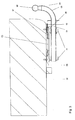
- the trailer coupling 01 according to the invention comprises a holder 03 fixedly connected to the underbody 02 of a vehicle and a coupling shank 04.
- a first end of the coupling shank 04 is mounted so as to be pivotable about its longitudinal axis in the holder 03.
- a coupling member 05 is arranged at a second end of the coupling shaft 04. This second end is provided with a bend 06.
- Fig. 3 can be seen that the coupling shaft 04 is aligned in the coupling position substantially in the vehicle longitudinal direction.
- the bending 06 having the end of the coupling shaft 04 is directed in the coupling position away from the roadway upwards.
- the coupling shaft 04 is disposed in a storage position below the vehicle.
- the bend 06 having the end of the coupling shaft 04 is arranged in this storage position substantially in a plane extending horizontally to the roadway.
- the holder 03 serving for supporting the coupling shaft 04 comprises a first bearing with an inner ring 07 and an outer ring 08.
- the inner ring 07 is preferably fastened to the underbody 02 of the vehicle via mechanical connecting means, for example screws 09. It has proven to be advantageous if the inner ring 07 is designed as a sheet metal forming part.
- On the outer ring 08 two opposing second bearings 11 are arranged. These second bearings 11 are used to support the coupling shaft 04.
- the first and / or the second bearing may be rolling or plain bearings.
- the outer ring 08 of the first bearing has a toothing 12 opposite the first end of the coupling shaft.
- This toothing 12 which may for example be designed as a worm wheel, is in engagement with a toothed wheel 13.
- the toothing 12 and the toothed wheel 13 form a first adjusting means, which serves to pivot the coupling shaft about a vertical axis.
- the gear 13 can be driven by a motor 14. Alternatively, a manual drive can be done.
- a rotation of the gear 13 causes a rotation of the outer ring 08 of the first bearing and thereby pivoting out of the coupling shaft 04 from the bottom 02 and a pivoting of the coupling shaft 04.
- the outer ring 08 can preferably be rotated by about 90 °. As a result of this rotation of the coupling shaft 04 is aligned in the swinging out substantially in the vehicle longitudinal direction.
- the inner ring 07 of the first bearing is provided with a toothing 16.
- the toothing 16 can be brought into engagement with a toothing 17 on the coupling shaft 04.
- These two gears 16, 17 together form a second adjusting means for rotating the coupling shaft 04 about its longitudinal axis.
- For engagement of the two gears 16, 17 occurs when pivoted out of the underbody 02 clutch shaft 04.
- the time required to erect the coupling member 05 space is available.
- the coupling member 05 is in dome position or leaves the coupling position when the clutch is to be pivoted back into the storage position.
- a rotation about 90 ° about the longitudinal axis of the coupling shaft 04 has proven to be particularly favorable.
- a socket 18 is arranged, which serves for the power supply of the coupling to be coupled to the trailer (not shown).
- the socket 18 is pivoted together with the coupling shaft 04 from the subfloor 02 or pivoted under the vehicle when the storage position is taken.
- the outer ring 08 of the first bearing may further comprise a protective cover 19.
- the protective cover 19 is used in the storage position pivoted coupling shaft 04 for closing the resulting opening and thus protects them from contamination.
- the pivoting of the trailer coupling according to the invention can be removed from the storage position to the coupling position.
- the motor 14 drives the gear 13.
- a rotation of the outer ring 08 of the first bearing and thus a pivoting of the coupling shaft 04 from the underbody 02 of the vehicle is effected.
- the toothings 16, 17 of the inner race 07 of the first bearing and of the coupling shaft 04 interlock with one another, which causes an elevation of the coupling member 05 during further pivoting.
- the trailer hitch is now ready for use.
- the coupling shaft 04 is aligned in the fully extended state substantially in the vehicle longitudinal direction and the coupling member 05 is directed away from the roadway upwards.
Landscapes
- Engineering & Computer Science (AREA)
- Transportation (AREA)
- Mechanical Engineering (AREA)
- Body Structure For Vehicles (AREA)
- Rolling Contact Bearings (AREA)
Abstract
Description
- Die Erfindung betrifft eine Anhängerkupplung für ein Fahrzeug gemäß dem Oberbegriff des Anspruchs 1. Eine gattungsgemäße Anhängerkupplung umfasst eine fest mit dem Unterboden des Fahrzeugs verbundene Halterung und einen Kupplungsschaft, dessen erstes Ende schwenkbar in der Halterung gelagert ist und dessen zweites Ende mit einem Kupplungsglied versehen ist und eine Biegung aufweist. Der Kupplungsschaft ist in einer Kuppelstellung im Wesentlichen in Fahrzeuglängsrichtung ausgerichtet, wobei das die Biegung aufweisende Ende von der Fahrbahn weg nach oben ausgerichtet ist. In einer Aufbewahrungsstellung ist der Kupplungsschaft unterhalb des Fahrzeugs angeordnet, wobei das die Biegung aufweisende Ende des Kupplungsschaftes im Wesentlichen in einer horizontal zur Fahrbahn verlaufenden Ebene angeordnet ist.
- In letzter Zeit werden statt der starren Anhängerkupplungen zunehmend auch abnehmbare Anhängerkupplungen verwendet, die falls sie nicht für Transportaufgaben benötigt werden, vom Fahrzeug entfernt werden können. Auf diese Weise sollen Verschmutzungen an der Bekleidung beim Beladen des Kofferraums vermieden werden. Außerdem haben sich Anhängerkupplungen als ungünstig bei Einparksystemen erwiesen, da sie die Sensoren dieser Systeme stören können. Nachteilig bei diesen abnehmbaren Kupplungen ist, dass diese sehr unbequem zu montieren bzw. zu demontieren sind. Am einfachsten gestaltet sich die Montage / Demontage mit einer Hebebühne, was aber zumeist einen Werkstattbesuch mit sich bringt. Als unbequemere Alternative kann man sich natürlich auch unter das Auto legen und die nötigen Arbeiten selber ausführen.
- Weiterhin sind schwenkbaren Anhängerkupplungen bekannt, die beispielsweise über den Innenraum des Kofferraums geschwenkt werden. Die bekannten Lösungen sind teilweise sehr aufwendig und kompliziert konstruiert. Einige zielen darauf, die Stoßstange zu unterfahren, während bei anderen Lösungen Kupplungselemente in die Ladefläche bei Transportern oder Kombis hineinragen.
- In der
DE 101 08 382 A1 ist eine bewegliche Anhängerkupplung beschrieben, mittels derer Pendelbewegungen bei Fahrzeuggespannen vermieden werden sollen. Die Anhängerkupplung ist über eine Führung am Zugfahrzeug befestigt und mittels Stellglieder in der Führung mit einer horizontalen Komponente quer zur Längsachse des Zugfahrzeugs verfahrbar. Die Bewegung der Anhängerkupplung wird von einem Steuergerät entsprechend einer in dem Steuergerät implementierten Fahrdynamikregelung geregelt. Die Anhängerkupplung wird in Richtung der Pendelbewegung der Anhängerdeichsel bewegt, so dass der Winkel zwischen Zugfahrzeug und Anhängerdeichsel bei Auftreten einer Pendelbewegung durch die Bewegung der Anhängerkupplung verkleinert wird. Die Beweglichkeit der Anhängerkupplung dient nicht dazu, diese in einer nicht zugängliche Position zu verschwenken. Die Anhängerkupplung ist stets zugänglich. - Die
FR 2 450 167 - Aus der
DE 10 2004 021 895 B4 ist eine Anhängerkupplung für ein Fahrzeug mit einem fahrzeugfesten Lager und einer an dem Lager angeordneten und gegenüber diesem zwischen einer aktiven und einer passiven Position verschwenkbaren Kupplungseinrichtung bekannt. Eine flexible abdichtende Abdeckung überdeckt zumindest einen Teilbereich des Lagers und des Kupplungsbereichs. Ein Distanzelement verhindert ein Einklemmen der flexiblen Abdeckung zwischen Lager und Kupplungseinrichtung. In ihrer passiven Position liegt die Anhängerkupplung am hinteren Teil des Fahrzeugs an. Damit reduziert sich zwar die Gesamtlänge des Fahrzeugs gegenüber der aktiven Position. Nach wie vor kann es jedoch zu Verschmutzungen der Bekleidung beim Beladen des Kofferraums kommen. - In der
DE 198 58 978 B5 ist eine schwenkbare Anhängerkupplung beschrieben, deren Kugelkopfstange in einem Gehäuse um eine Schwenkachse zwischen einer Ruhestellung und einer Betriebsstellung schwenkverstellbar gelagert ist. Hierzu weist die Kugelkopfstange an ihrem im Gehäuse gelagerten Ende einen Lagerblock auf. Die Kugelkopfstange ist zumindest in ihrer Betriebsstellung im Gehäuse derart verspannt, dass Relativbewegungen zwischen der Stange und dem Gehäuse vermieden werden. Durch die Verspannung soll die fahrdynamische Stabilität verbessert werden und eine Geräuschentwicklung in der Anhängerkupplung reduziert werden. Die Anhängerkupplung ist derart mit ihrem Gehäuse am Fahrzeug befestigt, dass die Stange in ihrer Ruhestellung von außen nicht erkennbar ist. - Die
EP 1 557 300 A1 beinhaltet eine Anhängerkupplung mit einem Lagerelement, welches zwischen einer Rückseite eines unteren Heckbereichs und einem Stoßfänger eines Fahrzeugs montierbar ist. Ein Anhängeelement mit einem Kugelhals und einer Kupplungskugel kann von einer Arbeitsstellung in eine Ruhestellung bewegt werden, in welcher Kugelhals und Kupplungskugel in dem Zwischenraum zwischen Stoßfänger und Rückseite des unteren Heckbereichs angeordnet sind. Das bewegbare Anhängeelement ist mittels einer Fixiereinrichtung zumindest in der Arbeitsstellung an dem Lagerelement formschlüssig festlegbar. Das Anhängeelement kann relativ zum Lagerelement in einer Verschieberichtung zwischen einer das Anhängeelement gegenüber dem Lagerelement mehrachsig schwenkbar lagernden Schwenkstellung und einer das Anhängeelement gegenüber dem Lagerelement drehfest haltenden Fixierstellung verschoben werden. - Aus der
DE 100 04 523 A1 ist eine Anhängerkupplung bekannt, bei der der Kupplungsarm zwischen einer von einem Fahrzeugteil, insbesondere einem Stoßfänger, verdeckten Nichtgebrauchsstellung und einer freiliegenden Gebrauchsstellung verstellbar ist. Zum Verstellung dient eine vom Fahrer des Fahrzeugs im Fahrzeug-Innenraum einschaltbare Motoranordnung. Die Kupplung wird zunächst nach unten entlang einer vertikalen Achse verschoben, anschließend ca. 90° um diese vertikale gedreht und nun wieder vertikal nach oben hinter die Stoßstange versenkt. - Bei der in der
DE 200 03 480 U1 beschriebenen Anhängerkupplung ist der Kupplungsschaft zwischen einer Kuppelstellung und einer Aufbewahrungsstellung verschwenkbar an einer fest mit dem Fahrzeug verbundenen Halterung abgestützt. In der Aufbewahrungsstellung ist das Kupplungsglied nach vorne und zur Seite gerichtet, so dass der Kupplungsschaft in dieser Stellung nicht mehr heckseitig über das Fahrzeug übersteht und unter dem Fahrzeug untergebracht werden kann. Der Kupplungsschaft ist vorzugsweise in einem Rohrstück gehalten, welches in Drehlagern schwenkbar an der Halterung abgestützt ist. Zum Arretieren des Kupplungsschaftes in der Kuppelstellung weist der Kupplungsschaft wie auch bei derFR 2 450 167 - Aus der gattungsbildenden
FR 2 227 739 A1 US 6 712 381 B1 sind Kupplungsvorrichtungen bekannt, die um eine vertikale Achse und um ihre Längsachse schwenkbar sind. Auch bei diesen Vorrichtungen sind Arretierstifte nötig, um den Kupplungsschaft zu sichern. - Die Aufgabe der vorliegenden Erfindung besteht darin, eine verbesserte verschwenkbare Anhängerkupplung für ein Fahrzeug zur Verfügung zu stellen, die in einer Ruhestellung platzsparend am Unterboden des Fahrzeugs angeordnet ist, welche sich durch einen einfachen Aufbau auszeichnet und mit welcher nur vergleichsweise geringe Zusatzkosten bei der Montage verbunden sind.
- Zur Lösung der erfindungsgemäßen Aufgabe dient eine Anhängerkupplung gemäß dem beigefügten Anspruch 1. Erfindungsgemäß erfolgt zum Verbringen eines Kupplungsschaftes einer Anhängerkupplung von einer Aufbewahrungsstellung in eine Kuppelstellung ein Verschwenken des Kupplungsschaftes um eine vertikale Achse mit einem ersten Stellmittel und ein Verschwenken des Kupplungsschaftes um seine horizontale Längsachse mit einem zweiten Stellmittel. Die erfindungsgemäßen Anhängerkupplung zeichnet sich dadurch aus, dass die zur Halterung des Kupplungsschaftes dienende Halterung ein erstes Lager mit einem mit dem Unterboden verbundenen feststehenden ersten Lagering (vorzugsweise der Innenring) und einem drehbaren zweiten Lagerring (vorzugsweise der Außenring) aufweist. An dem Außenring des ersten Lagers sind zwei sich gegenüberliegende zweite Lager angeordnet, wobei die zweiten Lager zum Lagern des Kupplungsschaftes dienen. Mittels des ersten Stellmittels ist vorzugsweise der Außenring gegenüber dem Innenring verdrehbar.
- Weiterhin ist der Innenring des ersten Lagers über das zweite Stellmittel mit dem aus dem Unterboden ausgeschwenkten Kupplungsschaft verbunden. Durch Drehen des Außenrings des zweiten Lagers und eine Betätigung des zweiten Stellmittels wird ein Verschwenken des Kupplungsschaftes von der Aufbewahrungsstellung in die Kuppelstellung und umgekehrt ermöglicht.
- In einer abgewandelten Ausführungsform kann eine Funktionsumkehr zwischen Außenring und Innenring vorgenommen werden, sodass der Innenring drehbar und der Außenring fest am Fahrzeugboden angeordnet sind.
- Ein besonderer Vorteil der erfindungsgemäßen Lösung besteht darin, dass auf vergleichsweise relativ einfache Art und Weise ein Verschwenken des Kupplungsschaftes von der Aufbewahrungsstellung in die Kuppelstellung realisiert wird. Es entfallen die Sicherungselemente, die im Stand der Technik durch eine Durchgangsbohrung des Kupplungsschaftes angebracht sind. weiterhin muss keine axiale Verstellung des Kupplungsschaftes erfolgen, dadurch ist eine einfachere und preiswertere Lagerung des Kupplungsschaftes möglich.
- Kupplungsschaftes von der Aufbewahrungsstellung in die Kuppelstellung realisiert wird. Es entfallen die Sicherungselemente, die im Stand der Technik durch eine Durchgangsbohrung des Kupplungsschaftes angebracht sind. weiterhin muss keine axiale Verstellung des Kupplungsschaftes erfolgen, dadurch ist eine einfachere und preiswertere Lagerung des Kupplungsschaftes möglich.
- Ein Aufrichten des das Kupplungsglied tragenden Endes erfolgt erst, wenn der hierfür erforderliche Platz vorhanden ist, also erst nachdem der Kupplungsschaft aus dem Unterboden ausgeschwenkt ist.
- In der Aufbewahrungsstellung ist das Kupplungsglied in einer horizontal zur Fahrbahn verlaufenden Ebene angeordnet. Hierdurch kann der Kupplungsschaft gemeinsam mit dem Kupplungsglied platzsparend unter dem Fahrzeug verstaut werden.
- Bei einer vorteilhaften Ausführungsform ist der Außenring des ersten Lagers um etwa 90° drehbar. Außerdem hat es sich auch als sinnvoll erwiesen, wenn der Mechanismus zum Drehen des Kupplungsschaftes eine Drehung um etwa 90° um die Längsachse des Kupplungsschaftes ermöglicht. Hierdurch kann eine besonders platzsparende Aufbewahrung von Kupplungsschaft und Kupplungsglied realisiert werden.
- Von Vorteil ist es, wenn der Außenring des ersten Lagers eine dem ersten Ende des Kupplungsschaftes gegenüberliegende Verzahnung als erstes Stellmittel aufweist und diese Verzahnung mit einem Zahnrad in Eingriff steht. Die Verzahnung des Außenrings des ersten Lagers kann als Schneckenrad ausgeführt sein. Durch Drehen des Zahnrades werden eine Drehung des Außenrings und damit ein Verschwenken des Kupplungsschaftes bewirkt.
- Das Zahnrad kann manuell oder über einen Motor angetrieben werden. Der über zwei ineinander greifende Verzahnungen realisierte Verstellmechanismus stellt lediglich eine mögliche Ausführungsform dar. Andere Ausführungsformen sind durchaus möglich. Es muss lediglich sichergestellt werden, dass über diese eine Drehung des Außenrings realisiert werden kann.
- Weiterhin ist es zweckmäßig, wenn das zweite Stellmittel zum Drehen des Kupplungsschaftes eine Verzahnung am Innenring des ersten Lagers und eine mit dieser in Eingriff bringbare Verzahnung am Kupplungsschaft umfasst. Zum Eingriff der beiden Verzahnung kommt es, wenn der Kupplungsschaft aus dem Unterboden ausgeschwenkt ist und somit genügend Platz zum Aufrichten des Kupplungsgliedes vorhanden ist.
- Nach einer weiteren vorteilhaften Ausführungsform ist am Außenring des ersten Lagers eine Steckdose angeordnet. Beim Drehen des Außenrings wird die Steckdose gemeinsam mit dem Kupplungsschaft nach außen geschwenkt und steht somit zur Stromversorgung des Anhängers zur Verfügung.
- Bei einer weiteren vorteilhaften Ausführungsform ist am Außenring des ersten Lagers eine Schutzabdeckung zum Verschließen einer beim Verschwenken des Kupplungsschaftes in Aufbewahrungsstellung entstehenden Öffnung angeordnet ist. Auf diese Weise kann eine Verschmutzung dieser Öffnung verhindert werden.
- Weitere Vorteile, Einzelheiten und Weiterbildungen der vorliegenden Erfindung ergeben sich aus der nachfolgenden Beschreibung einer bevorzugten Ausführungsform, unter Bezugnahme auf die Zeichnung. Es zeigen:
- Fig. 1
- eine erfindungsgemäße Anhängerkupplung in Kuppelstellung in einer Ansicht von hinten;
- Fig. 2
- die erfindungsgemäße Anhängerkupplung in Aufbewahrungsstellung in einer Ansicht von hinten;
- Fig. 3
- eine Schnittansicht der erfindungsgemäßen Anhängerkupplung entlang einer Linie A-A in
Fig. 1 ; - Fig. 4
- die erfindungsgemäße Anhängerkupplung in Kuppelstellung in einer Ansicht von unten;
- Fig. 5
- die erfindungsgemäße Anhängerkupplung in Aufbewahrungsstellung in einer Ansicht von unten;
- Fig. 6
- das Verschwenken der erfindungsgemäßen Anhängerkupplung von der Aufbewahrungsstellung in die Kuppelstellung in einer Ansicht von unten.
- Die Beschreibung der Bestandteile der erfindungsgemäßen Anhängerkupplung erfolgt zunächst anhand der
Fig. 1 bis 5 . Die erfindungsgemäße Anhängerkupplung 01 umfasst eine fest mit dem Unterboden 02 eines Fahrzeuges verbundene Halterung 03 sowie einen Kupplungsschaft 04. Ein erstes Ende des Kupplungsschaftes 04 ist um seine Längsachse schwenkbar in der Halterung 03 gelagert. An einem zweiten Ende des Kupplungsschaftes 04 ist ein Kupplungsglied 05 angeordnet. Dieses zweite Ende ist mit einer Biegung 06 versehen. -
Fig. 3 kann entnommen werden, dass der Kupplungsschaft 04 in Kuppelstellung im Wesentlichen in Fahrzeuglängsrichtung ausgerichtet ist. Das die Biegung 06 aufweisende Ende des Kupplungsschaftes 04 ist in der Kuppelstellung von der Fahrbahn weg nach oben gerichtet. - Wie
Fig. 5 entnommen werden kann, ist der Kupplungsschaft 04 in einer Aufbewahrungsstellung unterhalb des Fahrzeugs angeordnet. Das die Biegung 06 aufweisende Ende des Kupplungsschaftes 04 ist in dieser Aufbewahrungsstellung im Wesentlichen in einer horizontal zur Fahrbahn verlaufenden Ebene angeordnet. - Die zum Lagern des Kupplungsschaftes 04 dienende Halterung 03 umfasst ein erstes Lager mit einem Innenring 07 und einem Außenring 08. Der Innenring 07 ist vorzugsweise über mechanische Verbindungsmittel, beispielsweise Schrauben 09, am Unterboden 02 des Fahrzeugs befestigt. Als zweckmäßig hat es sich erwiesen, wenn der Innenring 07 als Blechumformteil ausgeführt ist. Am Außenring 08 sind zwei sich gegenüberliegende zweite Lager 11 angeordnet. Diese zweiten Lager 11 dienen zum Lagern des Kupplungsschaftes 04. Das erste und / oder die zweiten Lager können Wälzlager oder Gleitlager sein.
- Der Außenring 08 des ersten Lagers weist eine dem ersten Ende des Kupplungsschaftes gegenüberliegende Verzahnung 12 auf. Diese Verzahnung 12, die beispielsweise als Schneckenrad ausgeführt sein kann, steht in Eingriff mit einem Zahnrad 13. Verzahnung 12 und Zahnrad 13 bilden ein erstes Stellmittel, welches dem Verschwenken des Kupplungsschaftes um eine vertikale Achse dient. In der dargestellten Ausführungsform kann das Zahnrad 13 über einen Motor 14 angetrieben werden. Alternativ kann auch ein manueller Antrieb erfolgen. Ein Drehen des Zahnrads 13 bewirkt ein Drehen des Außenrings 08 des ersten Lagers und dadurch ein Herausschwenken des Kupplungsschaftes 04 aus dem Unterboden 02 bzw. ein Einschwenken des Kupplungsschaftes 04. Der Außenring 08 kann vorzugsweise um etwa 90° gedreht werden. Im Ergebnis dieser Drehung ist der Kupplungsschaft 04 beim Herausschwenkvorgang im Wesentlichen in Fahrzeuglängsrichtung ausgerichtet.
- Der Innenring 07 des ersten Lagers ist mit einer Verzahnung 16 versehen. Die Verzahnung 16 kann mit einer Verzahnung 17 am Kupplungsschaft 04 in Eingriff gebracht werden. Diese beiden Verzahnungen 16, 17 bilden gemeinsam ein zweites Stellmittel zum Drehen des Kupplungsschaftes 04 um dessen Längsachse. Zum Eingriff der beiden Verzahnungen 16, 17 kommt es bei aus dem Unterboden 02 ausgeschwenktem Kupplungsschaft 04. Zu diesem Zeitpunkt ist der zum Aufrichten des Kupplungsgliedes 05 erforderliche Raum vorhanden. Im Ergebnis der Drehung richtet sich das Kupplungsglied 05 in Kuppelstellung auf bzw. verlässt die Kuppelstellung, wenn die Kupplung in die Aufbewahrungsstellung zurück verschwenkt werden soll. Als besonders günstig hat sich dabei eine Drehung um etwa 90° um die Längsachse des Kupplungsschaftes 04 erwiesen.
- Am Außenring 08 des ersten Lagers ist eine Steckdose 18 angeordnet, welche zur Stromversorgung des an die Kupplung anzukoppelnden Anhängers (nicht gezeigt) dient. Die Steckdose 18 wird gemeinsam mit dem Kupplungsschaft 04 aus dem Unterboden 02 herausgeschwenkt bzw. unter das Fahrzeug verschwenkt, wenn die Aufbewahrungsstellung eingenommen wird.
- Der Außenring 08 des ersten Lagers kann weiterhin eine Schutzabdeckung 19 aufweisen. Die Schutzabdeckung 19 dient bei in Aufbewahrungsstellung verschwenktem Kupplungsschaft 04 zum Verschließen der dabei entstehenden Öffnung und schützt diese somit vor Verschmutzung.
-
Fig. 6 kann das Verschwenken der erfindungsgemäßen Anhängerkupplung von der Aufbewahrungsstellung in die Kuppelstellung entnommen werden. Der Motor 14 treibt das Zahnrad 13 an. Dabei wird ein Drehen des Außenrings 08 des ersten Lagers und somit ein Verschwenken des Kupplungsschaftes 04 aus dem Unterboden 02 des Fahrzeugs bewirkt. Sobald der Kupplungsschaft 04 aus dem Unterboden 02 herausgeschwenkt ist, greifen die Verzahnungen 16, 17 des Innenrings 07 des ersten Lagers und des Kupplungsschaftes 04 ineinander ein, wodurch während des weiteren Verschwenkens ein Aufrichten des Kupplungsgliedes 05 bewirkt wird. Die Anhängerkupplung ist nun betriebsbereit. Der Kupplungsschaft 04 ist im vollständig ausgeschwenkten Zustand im Wesentlichen in Fahrzeuglängsrichtung ausgerichtet und das Kupplungsglied 05 ist von der Fahrbahn weg nach oben gerichtet. -
- 01
- Anhängerkupplung
- 02
- Unterboden
- 03
- Halterung
- 04
- Kupplungsschaft
- 05
- Kupplungsglied
- 06
- Biegung des Kupplungsschaftes
- 07
- Innenring des ersten Lagers
- 08
- Außenring des ersten Lagers
- 09
- Schrauben
- 10
- -
- 11
- zweite Lager
- 12
- Verzahnung des Außenrings des ersten Lagers
- 13
- Zahnrad
- 14
- Motor
- 15
- -
- 16
- Verzahnung des Innenrings des ersten Lagers
- 17
- Verzahnung am Kupplungsschaft
- 18
- Steckdose
- 19
- Schutzabdeckung
Claims (15)
- Anhängerkupplung (01) für ein Fahrzeug mit einem Kupplungsschaft (04) und mit einer fest mit einem Unterboden (02) des Fahrzeugs verbundenen Halterung, wobei die Halterung ein erstes und ein zweites Stellmittel zum Verschwenken des Kupplungsschaftes (04) in eine Kuppelstellung und in eine Aufbewahrungsstellung aufweist, wobei das erste Stellmittel zum Verschwenken des Kupplungsschaftes (04) um eine vertikale Achse und das zweite Stellmittel zum Verschwenken des Kupplungsschaftes (04) um seine Längsachse dient, dadurch gekennzeichnet, dassa. ein erstes Lager einen mit dem Unterboden (02) verbundenen ersten Lagerring (07) und einen drehbaren zweiten Lagering (08) aufweist,b. der Kupplungsschaft (04) um seine Längsachse verschwenkbar an dem drehbaren zweiten Lagerring (08) des ersten Lagers angeordnet ist,c. der feststehende erste Lagerring (07) des ersten Lagers über das zweite Stellmittel mit dem aus dem Unterboden (02) ausgeschwenkten Kupplungsschaft (04) verbunden ist,wobei ein Drehen des zweiten Lagerrings (08) des ersten Lagers und eine Betätigung des zweiten Stellmittels ein Verschwenken des Kupplungsschaftes (04) von der Aufbewahrungsstellung in die Kuppelstellung und umgekehrt ermöglicht.
- Anhängerkupplung (01) nach Anspruch 1, dadurch gekennzeichnet, dass der erste Lagerring als Innenring (07) und der zweite Lagerring als Außenring (08) ausgebildet ist.
- Anhängerkupplung (01) nach Anspruch 2, dadurch gekennzeichnet, dass der Außenring (08) des ersten Lagers um etwa 90° drehbar ist.
- Anhängerkupplung (01) nach einem der Ansprüche 1 bis 3, dadurch gekennzeichnet, dass das zweite Stellmittel eine Drehung um etwa 90° um die Längsachse des Kupplungsschaftes (04) bewirkt.
- Anhängerkupplung (01) nach einem der Ansprüche 2 bis 4, dadurch gekennzeichnet, dass der Außenring (08) des ersten Lagers als erstes Stellmittel eine dem ersten Ende des Kupplungsschaftes (04) gegenüberliegende Verzahnung (12) aufweist, dass diese Verzahnung (12) mit einem Zahnrad (13) in Eingriff steht.
- Anhängerkupplung (01) nach Anspruch 5, dadurch gekennzeichnet, dass die Verzahnung des Außenrings (08) des ersten Lagers als Schneckenrad ausgeführt ist.
- Anhängerkupplung (01) nach Anspruch 5 oder 6, dadurch gekennzeichnet, dass das Zahnrad (13) manuell antreibbar ist.
- Anhängerkupplung (01) nach Anspruch 5 oder 6, dadurch gekennzeichnet, dass das Zahnrad (13) über einen Motor (14) antreibbar ist.
- Anhängerkupplung (01) nach einem der Ansprüche 2 bis 8, dadurch gekennzeichnet, dass das zweite Stellmittel zum Drehen des Kupplungsschaftes (04) eine Verzahnung (16) am Innenring (07) des ersten Lagers und eine mit dieser in Eingriff bringbare Verzahnung (17) am Kupplungsschaft (04) umfasst, wobei die Verzahnung (17) am Kupplungsschaft (04) in die Verzahnung (16) am Innenring (07) des ersten Lagers bei aus dem Unterboden (02) ausgeschwenkten Kupplungsschaft (04) eingreift.
- Anhängerkupplung (01) nach einem der Ansprüche 2 bis 9, dadurch gekennzeichnet, dass am Außenring (08) des ersten Lagers eine Steckdose (18) angeordnet ist.
- Anhängerkupplung (01) nach einem der Ansprüche 1 bis 10, dadurch gekennzeichnet, dass der erste Lagerring (07) des ersten Lagers über mechanische Verbindungsmittel (09) am Unterboden (02) des Fahrzeugs befestigt ist.
- Anhängerkupplung (01) nach einem der Ansprüche 1 bis 11, dadurch gekennzeichnet, dass am drehbaren zweiten Lagerring (08) des ersten Lagers zwei sich gegenüberliegende zweite Lager (11) angeordnet sind, wobei die zweiten Lager (11) zum Lagern des Kupplungsschaftes (04) dienen.
- Anhängerkupplung (01) nach Anspruch 12, dadurch gekennzeichnet, dass die zweiten Lager (11) Wälzlager oder Gleitlager sind.
- Anhängerkupplung (01) nach einem der Ansprüche 1 bis 13, dadurch gekennzeichnet, dass das erste Lager (07, 08) ein Wälzlager oder ein Gleitlager ist.
- Anhängerkupplung (01) nach einem der Ansprüche 1 bis 14, dadurch gekennzeichnet, dass am drehbaren zweiten Lagerring (08) des ersten Lagers eine Schutzabdeckung (19) zum Verschließen einer beim Verschwenken des Kupplungsschaftes (04) in Aufbewahrungsstellung entstehenden Öffnung angeordnet ist.
Applications Claiming Priority (2)
| Application Number | Priority Date | Filing Date | Title |
|---|---|---|---|
| DE200810014135 DE102008014135A1 (de) | 2008-03-13 | 2008-03-13 | Verschwenkbare Anhängerkupplung |
| PCT/EP2009/001654 WO2009112217A1 (de) | 2008-03-13 | 2009-03-07 | Verschwenkbare anhängerkupplung |
Publications (2)
| Publication Number | Publication Date |
|---|---|
| EP2265451A1 EP2265451A1 (de) | 2010-12-29 |
| EP2265451B1 true EP2265451B1 (de) | 2012-05-30 |
Family
ID=40521877
Family Applications (1)
| Application Number | Title | Priority Date | Filing Date |
|---|---|---|---|
| EP09719485A Not-in-force EP2265451B1 (de) | 2008-03-13 | 2009-03-07 | Verschwenkbare anhängerkupplung |
Country Status (3)
| Country | Link |
|---|---|
| EP (1) | EP2265451B1 (de) |
| DE (1) | DE102008014135A1 (de) |
| WO (1) | WO2009112217A1 (de) |
Families Citing this family (2)
| Publication number | Priority date | Publication date | Assignee | Title |
|---|---|---|---|---|
| DE102018204535B4 (de) * | 2018-03-26 | 2024-08-01 | Audi Ag | Wagenhebersystem und Wagenheber |
| AT524223B1 (de) * | 2021-04-29 | 2022-04-15 | Karl Wagner | Vorrichtung zum Aufnehmen eines Fahrradträgers |
Family Cites Families (10)
| Publication number | Priority date | Publication date | Assignee | Title |
|---|---|---|---|---|
| FR2227739A5 (en) | 1973-04-25 | 1974-11-22 | Gumuchian Pierre | Retracting drawgear for road type trailers - can be housed under trailer chassis when not in use |
| FR2450167A1 (fr) | 1979-02-27 | 1980-09-26 | Oppermann Rene | Dispositif d'attelage escamotable pour remorque |
| US6712381B1 (en) | 1999-10-29 | 2004-03-30 | Wing Enterprises, Inc. | Pivoting, underslung, stowaway, hitch mount |
| DE10004523A1 (de) | 2000-02-02 | 2001-08-09 | Fac Frank Abels Consult & Tech | Anhängerkupplung |
| DE20003480U1 (de) | 2000-02-25 | 2000-05-31 | Sauermann, Hans, 85119 Ernsgaden | Anhängerkupplung für ein Fahrzeug, insbesondere für einen Personenkraftwagen |
| DE10108382A1 (de) | 2001-02-21 | 2002-09-12 | Daimler Chrysler Ag | Bewegliche Anhängerkupplung zur Vermeidung von Pendelbewegungen bei Fahrzeuggespannen |
| EP1478528B1 (de) * | 2002-02-28 | 2006-01-11 | Al-Ko Kober Ag | Schwenkbare anhängevorrichtung für zugfahrzeuge |
| DE102004004504A1 (de) | 2004-01-22 | 2005-08-18 | Oris Fahrzeugteile Hans Riehle Gmbh | Anhängekupplung |
| DE102004021895B4 (de) | 2004-05-04 | 2006-05-11 | Daimlerchrysler Ag | Anhängekupplung für ein Fahrzeug |
| DE202006011346U1 (de) * | 2006-07-20 | 2007-11-22 | Al-Ko Kober Ag | Schwenkbare Anhängevorrichtung für Zugfahrzeuge |
-
2008
- 2008-03-13 DE DE200810014135 patent/DE102008014135A1/de not_active Withdrawn
-
2009
- 2009-03-07 WO PCT/EP2009/001654 patent/WO2009112217A1/de not_active Ceased
- 2009-03-07 EP EP09719485A patent/EP2265451B1/de not_active Not-in-force
Also Published As
| Publication number | Publication date |
|---|---|
| DE102008014135A1 (de) | 2009-09-17 |
| WO2009112217A1 (de) | 2009-09-17 |
| EP2265451A1 (de) | 2010-12-29 |
Similar Documents
| Publication | Publication Date | Title |
|---|---|---|
| EP0850147B2 (de) | Anhängerkupplung für kraftfahrzeuge | |
| EP1435305B1 (de) | Anhängekupplung | |
| EP3820740B1 (de) | Rückblickvorrichtung und fahrzeug mit einer solchen rückblickvorrichtung | |
| DE102011113747B4 (de) | Beschlagsystem für einen Fahrzeugsitz und Fahrzeugsitz | |
| EP1880879B1 (de) | Schwenkbare Anhängevorrichtung für Zugfahrzeuge | |
| EP1902871B1 (de) | Anhängekupplung | |
| DE102013007114A1 (de) | Anhängekupplung | |
| EP2289743B1 (de) | Hubstütze | |
| EP1905617B1 (de) | Anhängerkupplung | |
| DE202019107144U1 (de) | Ausfahrbare Trittstufe | |
| DE102009045290A1 (de) | Taumelkugelgelenk | |
| DE202009011491U1 (de) | Fahrgestell | |
| EP3867133A1 (de) | Hubvorrichtung zur rotatorischen fortbewegung eines kraftfahrzeugs | |
| EP2265451B1 (de) | Verschwenkbare anhängerkupplung | |
| EP1541385A1 (de) | Anhängerkupplung für Kraftfahrzeuge | |
| DE102012023571B4 (de) | Kippeinrichtung zum Kippen eines Fahrerhauses und Nutzfahrzeug | |
| DE102013007122A1 (de) | Anhängekupplung | |
| EP2799261B1 (de) | Anhängekupplung | |
| DE102018005268B4 (de) | Vorrichtung zum Umklappen einer Sitzlehne eines Fahrzeugsitzes | |
| DE102007033599B3 (de) | Hilfsantriebseinrichtung für antriebslose Fahrzeuganhänger, insbesondere Caravan-Rangierhilfe | |
| DE202004006666U1 (de) | Anhängerkupplung | |
| DE102012011070A1 (de) | Betätigungssystem für eine Anhängekupplung eines Kraftfahrzeugs | |
| EP3287347B1 (de) | Hilfsantrieb für einen anhänger und anhänger | |
| DE102012011069A1 (de) | Betätigungssystem für eine Anhängekupplung eines Kraftfahrzeugs | |
| DE102014005881A1 (de) | Anhängekupplung |
Legal Events
| Date | Code | Title | Description |
|---|---|---|---|
| PUAI | Public reference made under article 153(3) epc to a published international application that has entered the european phase |
Free format text: ORIGINAL CODE: 0009012 |
|
| 17P | Request for examination filed |
Effective date: 20101013 |
|
| AK | Designated contracting states |
Kind code of ref document: A1 Designated state(s): AT BE BG CH CY CZ DE DK EE ES FI FR GB GR HR HU IE IS IT LI LT LU LV MC MK MT NL NO PL PT RO SE SI SK TR |
|
| AX | Request for extension of the european patent |
Extension state: AL BA RS |
|
| DAX | Request for extension of the european patent (deleted) | ||
| GRAP | Despatch of communication of intention to grant a patent |
Free format text: ORIGINAL CODE: EPIDOSNIGR1 |
|
| RAP1 | Party data changed (applicant data changed or rights of an application transferred) |
Owner name: SCHAEFFLER TECHNOLOGIES AG & CO. KG |
|
| GRAS | Grant fee paid |
Free format text: ORIGINAL CODE: EPIDOSNIGR3 |
|
| GRAA | (expected) grant |
Free format text: ORIGINAL CODE: 0009210 |
|
| AK | Designated contracting states |
Kind code of ref document: B1 Designated state(s): AT BE BG CH CY CZ DE DK EE ES FI FR GB GR HR HU IE IS IT LI LT LU LV MC MK MT NL NO PL PT RO SE SI SK TR |
|
| REG | Reference to a national code |
Ref country code: GB Ref legal event code: FG4D Free format text: NOT ENGLISH |
|
| REG | Reference to a national code |
Ref country code: CH Ref legal event code: EP |
|
| REG | Reference to a national code |
Ref country code: AT Ref legal event code: REF Ref document number: 559897 Country of ref document: AT Kind code of ref document: T Effective date: 20120615 |
|
| REG | Reference to a national code |
Ref country code: IE Ref legal event code: FG4D Free format text: LANGUAGE OF EP DOCUMENT: GERMAN |
|
| REG | Reference to a national code |
Ref country code: DE Ref legal event code: R096 Ref document number: 502009003676 Country of ref document: DE Effective date: 20120726 |
|
| REG | Reference to a national code |
Ref country code: NL Ref legal event code: VDEP Effective date: 20120530 |
|
| REG | Reference to a national code |
Ref country code: LT Ref legal event code: MG4D Effective date: 20120530 |
|
| PG25 | Lapsed in a contracting state [announced via postgrant information from national office to epo] |
Ref country code: IS Free format text: LAPSE BECAUSE OF FAILURE TO SUBMIT A TRANSLATION OF THE DESCRIPTION OR TO PAY THE FEE WITHIN THE PRESCRIBED TIME-LIMIT Effective date: 20120930 Ref country code: FI Free format text: LAPSE BECAUSE OF FAILURE TO SUBMIT A TRANSLATION OF THE DESCRIPTION OR TO PAY THE FEE WITHIN THE PRESCRIBED TIME-LIMIT Effective date: 20120530 Ref country code: LT Free format text: LAPSE BECAUSE OF FAILURE TO SUBMIT A TRANSLATION OF THE DESCRIPTION OR TO PAY THE FEE WITHIN THE PRESCRIBED TIME-LIMIT Effective date: 20120530 Ref country code: CY Free format text: LAPSE BECAUSE OF FAILURE TO SUBMIT A TRANSLATION OF THE DESCRIPTION OR TO PAY THE FEE WITHIN THE PRESCRIBED TIME-LIMIT Effective date: 20120530 Ref country code: SE Free format text: LAPSE BECAUSE OF FAILURE TO SUBMIT A TRANSLATION OF THE DESCRIPTION OR TO PAY THE FEE WITHIN THE PRESCRIBED TIME-LIMIT Effective date: 20120530 Ref country code: NO Free format text: LAPSE BECAUSE OF FAILURE TO SUBMIT A TRANSLATION OF THE DESCRIPTION OR TO PAY THE FEE WITHIN THE PRESCRIBED TIME-LIMIT Effective date: 20120830 |
|
| PG25 | Lapsed in a contracting state [announced via postgrant information from national office to epo] |
Ref country code: LV Free format text: LAPSE BECAUSE OF FAILURE TO SUBMIT A TRANSLATION OF THE DESCRIPTION OR TO PAY THE FEE WITHIN THE PRESCRIBED TIME-LIMIT Effective date: 20120530 Ref country code: SI Free format text: LAPSE BECAUSE OF FAILURE TO SUBMIT A TRANSLATION OF THE DESCRIPTION OR TO PAY THE FEE WITHIN THE PRESCRIBED TIME-LIMIT Effective date: 20120530 Ref country code: GR Free format text: LAPSE BECAUSE OF FAILURE TO SUBMIT A TRANSLATION OF THE DESCRIPTION OR TO PAY THE FEE WITHIN THE PRESCRIBED TIME-LIMIT Effective date: 20120831 Ref country code: HR Free format text: LAPSE BECAUSE OF FAILURE TO SUBMIT A TRANSLATION OF THE DESCRIPTION OR TO PAY THE FEE WITHIN THE PRESCRIBED TIME-LIMIT Effective date: 20120530 |
|
| PG25 | Lapsed in a contracting state [announced via postgrant information from national office to epo] |
Ref country code: NL Free format text: LAPSE BECAUSE OF FAILURE TO SUBMIT A TRANSLATION OF THE DESCRIPTION OR TO PAY THE FEE WITHIN THE PRESCRIBED TIME-LIMIT Effective date: 20120530 Ref country code: DK Free format text: LAPSE BECAUSE OF FAILURE TO SUBMIT A TRANSLATION OF THE DESCRIPTION OR TO PAY THE FEE WITHIN THE PRESCRIBED TIME-LIMIT Effective date: 20120530 Ref country code: SK Free format text: LAPSE BECAUSE OF FAILURE TO SUBMIT A TRANSLATION OF THE DESCRIPTION OR TO PAY THE FEE WITHIN THE PRESCRIBED TIME-LIMIT Effective date: 20120530 Ref country code: CZ Free format text: LAPSE BECAUSE OF FAILURE TO SUBMIT A TRANSLATION OF THE DESCRIPTION OR TO PAY THE FEE WITHIN THE PRESCRIBED TIME-LIMIT Effective date: 20120530 Ref country code: EE Free format text: LAPSE BECAUSE OF FAILURE TO SUBMIT A TRANSLATION OF THE DESCRIPTION OR TO PAY THE FEE WITHIN THE PRESCRIBED TIME-LIMIT Effective date: 20120530 Ref country code: RO Free format text: LAPSE BECAUSE OF FAILURE TO SUBMIT A TRANSLATION OF THE DESCRIPTION OR TO PAY THE FEE WITHIN THE PRESCRIBED TIME-LIMIT Effective date: 20120530 |
|
| PG25 | Lapsed in a contracting state [announced via postgrant information from national office to epo] |
Ref country code: PT Free format text: LAPSE BECAUSE OF FAILURE TO SUBMIT A TRANSLATION OF THE DESCRIPTION OR TO PAY THE FEE WITHIN THE PRESCRIBED TIME-LIMIT Effective date: 20121001 Ref country code: IT Free format text: LAPSE BECAUSE OF FAILURE TO SUBMIT A TRANSLATION OF THE DESCRIPTION OR TO PAY THE FEE WITHIN THE PRESCRIBED TIME-LIMIT Effective date: 20120530 Ref country code: PL Free format text: LAPSE BECAUSE OF FAILURE TO SUBMIT A TRANSLATION OF THE DESCRIPTION OR TO PAY THE FEE WITHIN THE PRESCRIBED TIME-LIMIT Effective date: 20120530 |
|
| PLBE | No opposition filed within time limit |
Free format text: ORIGINAL CODE: 0009261 |
|
| STAA | Information on the status of an ep patent application or granted ep patent |
Free format text: STATUS: NO OPPOSITION FILED WITHIN TIME LIMIT |
|
| PG25 | Lapsed in a contracting state [announced via postgrant information from national office to epo] |
Ref country code: ES Free format text: LAPSE BECAUSE OF FAILURE TO SUBMIT A TRANSLATION OF THE DESCRIPTION OR TO PAY THE FEE WITHIN THE PRESCRIBED TIME-LIMIT Effective date: 20120910 |
|
| 26N | No opposition filed |
Effective date: 20130301 |
|
| REG | Reference to a national code |
Ref country code: DE Ref legal event code: R097 Ref document number: 502009003676 Country of ref document: DE Effective date: 20130301 |
|
| PG25 | Lapsed in a contracting state [announced via postgrant information from national office to epo] |
Ref country code: BG Free format text: LAPSE BECAUSE OF FAILURE TO SUBMIT A TRANSLATION OF THE DESCRIPTION OR TO PAY THE FEE WITHIN THE PRESCRIBED TIME-LIMIT Effective date: 20120830 |
|
| BERE | Be: lapsed |
Owner name: SCHAEFFLER TECHNOLOGIES A.G. & CO. KG Effective date: 20130331 |
|
| PG25 | Lapsed in a contracting state [announced via postgrant information from national office to epo] |
Ref country code: MC Free format text: LAPSE BECAUSE OF NON-PAYMENT OF DUE FEES Effective date: 20130331 |
|
| REG | Reference to a national code |
Ref country code: CH Ref legal event code: PL |
|
| GBPC | Gb: european patent ceased through non-payment of renewal fee |
Effective date: 20130307 |
|
| REG | Reference to a national code |
Ref country code: FR Ref legal event code: ST Effective date: 20131129 |
|
| REG | Reference to a national code |
Ref country code: IE Ref legal event code: MM4A |
|
| PG25 | Lapsed in a contracting state [announced via postgrant information from national office to epo] |
Ref country code: GB Free format text: LAPSE BECAUSE OF NON-PAYMENT OF DUE FEES Effective date: 20130307 Ref country code: BE Free format text: LAPSE BECAUSE OF NON-PAYMENT OF DUE FEES Effective date: 20130331 Ref country code: IE Free format text: LAPSE BECAUSE OF NON-PAYMENT OF DUE FEES Effective date: 20130307 Ref country code: CH Free format text: LAPSE BECAUSE OF NON-PAYMENT OF DUE FEES Effective date: 20130331 Ref country code: FR Free format text: LAPSE BECAUSE OF NON-PAYMENT OF DUE FEES Effective date: 20130402 Ref country code: LI Free format text: LAPSE BECAUSE OF NON-PAYMENT OF DUE FEES Effective date: 20130331 |
|
| REG | Reference to a national code |
Ref country code: DE Ref legal event code: R081 Ref document number: 502009003676 Country of ref document: DE Owner name: SCHAEFFLER TECHNOLOGIES AG & CO. KG, DE Free format text: FORMER OWNER: SCHAEFFLER TECHNOLOGIES AG & CO. KG, 91074 HERZOGENAURACH, DE Effective date: 20140218 Ref country code: DE Ref legal event code: R081 Ref document number: 502009003676 Country of ref document: DE Owner name: SCHAEFFLER TECHNOLOGIES GMBH & CO. KG, DE Free format text: FORMER OWNER: SCHAEFFLER TECHNOLOGIES AG & CO. KG, 91074 HERZOGENAURACH, DE Effective date: 20140218 |
|
| PG25 | Lapsed in a contracting state [announced via postgrant information from national office to epo] |
Ref country code: MT Free format text: LAPSE BECAUSE OF FAILURE TO SUBMIT A TRANSLATION OF THE DESCRIPTION OR TO PAY THE FEE WITHIN THE PRESCRIBED TIME-LIMIT Effective date: 20120530 |
|
| REG | Reference to a national code |
Ref country code: DE Ref legal event code: R081 Ref document number: 502009003676 Country of ref document: DE Owner name: SCHAEFFLER TECHNOLOGIES AG & CO. KG, DE Free format text: FORMER OWNER: SCHAEFFLER TECHNOLOGIES GMBH & CO. KG, 91074 HERZOGENAURACH, DE Effective date: 20150407 |
|
| REG | Reference to a national code |
Ref country code: AT Ref legal event code: MM01 Ref document number: 559897 Country of ref document: AT Kind code of ref document: T Effective date: 20140307 |
|
| PG25 | Lapsed in a contracting state [announced via postgrant information from national office to epo] |
Ref country code: TR Free format text: LAPSE BECAUSE OF FAILURE TO SUBMIT A TRANSLATION OF THE DESCRIPTION OR TO PAY THE FEE WITHIN THE PRESCRIBED TIME-LIMIT Effective date: 20120530 |
|
| PG25 | Lapsed in a contracting state [announced via postgrant information from national office to epo] |
Ref country code: MK Free format text: LAPSE BECAUSE OF FAILURE TO SUBMIT A TRANSLATION OF THE DESCRIPTION OR TO PAY THE FEE WITHIN THE PRESCRIBED TIME-LIMIT Effective date: 20120530 Ref country code: HU Free format text: LAPSE BECAUSE OF FAILURE TO SUBMIT A TRANSLATION OF THE DESCRIPTION OR TO PAY THE FEE WITHIN THE PRESCRIBED TIME-LIMIT; INVALID AB INITIO Effective date: 20090307 Ref country code: LU Free format text: LAPSE BECAUSE OF NON-PAYMENT OF DUE FEES Effective date: 20130307 |
|
| PG25 | Lapsed in a contracting state [announced via postgrant information from national office to epo] |
Ref country code: AT Free format text: LAPSE BECAUSE OF NON-PAYMENT OF DUE FEES Effective date: 20140307 |
|
| PGFP | Annual fee paid to national office [announced via postgrant information from national office to epo] |
Ref country code: DE Payment date: 20170531 Year of fee payment: 9 |
|
| REG | Reference to a national code |
Ref country code: DE Ref legal event code: R119 Ref document number: 502009003676 Country of ref document: DE |
|
| PG25 | Lapsed in a contracting state [announced via postgrant information from national office to epo] |
Ref country code: DE Free format text: LAPSE BECAUSE OF NON-PAYMENT OF DUE FEES Effective date: 20181002 |
|
| P01 | Opt-out of the competence of the unified patent court (upc) registered |
Effective date: 20230522 |