EP2265800B1 - Kühlkanalanordnung innerhalb eines hohlgegossenen gussteils - Google Patents
Kühlkanalanordnung innerhalb eines hohlgegossenen gussteils Download PDFInfo
- Publication number
- EP2265800B1 EP2265800B1 EP09727227.2A EP09727227A EP2265800B1 EP 2265800 B1 EP2265800 B1 EP 2265800B1 EP 09727227 A EP09727227 A EP 09727227A EP 2265800 B1 EP2265800 B1 EP 2265800B1
- Authority
- EP
- European Patent Office
- Prior art keywords
- ribs
- line
- contour
- cooling
- along
- Prior art date
- Legal status (The legal status is an assumption and is not a legal conclusion. Google has not performed a legal analysis and makes no representation as to the accuracy of the status listed.)
- Not-in-force
Links
Images

Classifications
-
- F—MECHANICAL ENGINEERING; LIGHTING; HEATING; WEAPONS; BLASTING
- F01—MACHINES OR ENGINES IN GENERAL; ENGINE PLANTS IN GENERAL; STEAM ENGINES
- F01D—NON-POSITIVE DISPLACEMENT MACHINES OR ENGINES, e.g. STEAM TURBINES
- F01D5/00—Blades; Blade-carrying members; Heating, heat-insulating, cooling or antivibration means on the blades or the members
- F01D5/12—Blades
- F01D5/14—Form or construction
- F01D5/18—Hollow blades, i.e. blades with cooling or heating channels or cavities; Heating, heat-insulating or cooling means on blades
- F01D5/187—Convection cooling
-
- F—MECHANICAL ENGINEERING; LIGHTING; HEATING; WEAPONS; BLASTING
- F05—INDEXING SCHEMES RELATING TO ENGINES OR PUMPS IN VARIOUS SUBCLASSES OF CLASSES F01-F04
- F05D—INDEXING SCHEME FOR ASPECTS RELATING TO NON-POSITIVE-DISPLACEMENT MACHINES OR ENGINES, GAS-TURBINES OR JET-PROPULSION PLANTS
- F05D2230/00—Manufacture
- F05D2230/20—Manufacture essentially without removing material
- F05D2230/21—Manufacture essentially without removing material by casting
-
- F—MECHANICAL ENGINEERING; LIGHTING; HEATING; WEAPONS; BLASTING
- F05—INDEXING SCHEMES RELATING TO ENGINES OR PUMPS IN VARIOUS SUBCLASSES OF CLASSES F01-F04
- F05D—INDEXING SCHEME FOR ASPECTS RELATING TO NON-POSITIVE-DISPLACEMENT MACHINES OR ENGINES, GAS-TURBINES OR JET-PROPULSION PLANTS
- F05D2240/00—Components
- F05D2240/10—Stators
- F05D2240/12—Fluid guiding means, e.g. vanes
- F05D2240/122—Fluid guiding means, e.g. vanes related to the trailing edge of a stator vane
-
- F—MECHANICAL ENGINEERING; LIGHTING; HEATING; WEAPONS; BLASTING
- F05—INDEXING SCHEMES RELATING TO ENGINES OR PUMPS IN VARIOUS SUBCLASSES OF CLASSES F01-F04
- F05D—INDEXING SCHEME FOR ASPECTS RELATING TO NON-POSITIVE-DISPLACEMENT MACHINES OR ENGINES, GAS-TURBINES OR JET-PROPULSION PLANTS
- F05D2240/00—Components
- F05D2240/20—Rotors
- F05D2240/30—Characteristics of rotor blades, i.e. of any element transforming dynamic fluid energy to or from rotational energy and being attached to a rotor
- F05D2240/304—Characteristics of rotor blades, i.e. of any element transforming dynamic fluid energy to or from rotational energy and being attached to a rotor related to the trailing edge of a rotor blade
-
- F—MECHANICAL ENGINEERING; LIGHTING; HEATING; WEAPONS; BLASTING
- F05—INDEXING SCHEMES RELATING TO ENGINES OR PUMPS IN VARIOUS SUBCLASSES OF CLASSES F01-F04
- F05D—INDEXING SCHEME FOR ASPECTS RELATING TO NON-POSITIVE-DISPLACEMENT MACHINES OR ENGINES, GAS-TURBINES OR JET-PROPULSION PLANTS
- F05D2260/00—Function
- F05D2260/20—Heat transfer, e.g. cooling
- F05D2260/221—Improvement of heat transfer
- F05D2260/2214—Improvement of heat transfer by increasing the heat transfer surface
- F05D2260/22141—Improvement of heat transfer by increasing the heat transfer surface using fins or ribs
Definitions
- the invention relates to a cooling channel arrangement within a hollow casted casting, with a flow area for a coolant which is delimited by at least two spaced-apart casting walls and which is subdivided into two cooling channels in the flow direction of at least one ribbed train connected to both casting walls.
- Hollow-cast parts with intimately provided cooling channel arrangements relate to the purposes of the invention primarily in gas and steam turbine to be integrated components that are operationally exposed to high process temperatures and to avoid thermally induced material degradation of effective cooling.
- Such castings in particular represent guide vanes and rotor blades within turbine stages, which are directly exposed to the hot gases of a gas turbine process.
- the cooling of such blading by means of cooling air, which is branched off on the compressor side and is fed via openings within the respective Schaufeifsente in the cavities having over blades for cooling purposes.
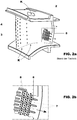
- FIG. 2 a and b shows a known guide vane, with a vane platform 1 and a Leitschaufeldeckband 2, between which extends the vane blade 3 with a vane leading edge 4 and a Leitschaufelhinterkante 5.
- cooling air K passes through both openings Within the vane cover 2 as well as within the vane platform 1.
- For effective cooling of the vane blade 3 are located in the interior of the vane flow contours, which ensure the most intimate possible thermal contact between the supplied cooling air and the inside to be cooled of the vane wall.
- Rippenver 6 are located in the flow direction Rippenver 6, each delimiting individual cooling channels 7 from each other.
- Such rib trains are also off, for example WO0100964 known.
- the rib trains are designed as Querlenkarm, which are arranged in packets side by side and are separated by a wall. The wall prevents the flow of coolant within a packet from entering the flow paths of an adjacent packet.
- lost cores are required for the casting process, in which the negative contours of all structures to be provided within the casting, in particular the flow contours affecting the cooling air flow, are to be incorporated.
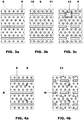
- FIG. 2b shown ribbed trains 6 and the pin-like pins 8 located therebetween form, for better illustration in FIG. 3a are shown again in a plan view, it is necessary to provide a casting core 9, the in FIG. 3b is also shown in a plan view, which must provide for the production of the individual rib trains via groove-like recesses 10 and for generating the pin-like pins 8 corresponding through holes 1 1.
- Previously consistently trained ribbed trains 6 could completely separate the cooling air flows K contained within the cooling channels 7 from each other, as shown in the schematic plan view in FIG. 4a is shown, then occur by providing appropriate interruptions 13 along the Rippentors 6, due to the stabilizing connecting webs 12 within the casting core, by the interruptions 13 branching cooling air flows K ', which are able to irritate the cooling air flow in the adjacent cooling channels.
- this reduces the cooling efficiency of the cooling air passing through the cooling channels 7, so that measures must be sought with which the passing through the interruptions 13 cooling air flow portions can be avoided.
- the invention is based on the object, a cooling arrangement within a hollow cast casting, with one of at least two spaced apart casting walls delimiting flow area for a coolant, which is divided in the flow direction of at least one connected to two casting walls Rippenyak in two cooling channels, such on the one hand the measures taken to stabilize the casting core required for the production of the casting should remain largely unaffected, but the cooling effect of passing through the cooling channel arrangement coolant should be significantly improved.
- a cooling arrangement within a hollow cast part is designed so that at least one interruption is provided along the at least one rib train, at which two rib ends are spaced apart, one end of the rib being contoured in the manner of a " Dog bone ".
- a flow contour it is possible, as the further embodiments will show, to largely or completely prevent coolant flow through the interruption along a rib train.
- the solution according to the measure only requires an additional contour along the Rippenzuges in the region of an interruption, by the stability of a casting core is not affected by any means. Even with the measure according to the solution, it is possible to provide connection areas between the cooling passages separated by the rib trains in order in this way to realize a self-contained and mechanically stable casting core.
- FIG. 1 a shows the region of an interruption 13 along a rib train 6, wherein two rib ends 61, 62 are spaced apart from each other along the rib train 6.
- a coolant flow K rests along the rib train 6 in the flow direction indicated by the arrows.
- the rib end 61 which is provided upstream of the interruption 13, in this case according to the solution has a contour 14 in the manner of a dog bone, whereby the coolant flow K not as in the illustrated case in example FIG. 4b in the context of cross-currents K 'passes through the interruptions 13, but in each case on both sides of the interruption 13 along the respective cooling channel 7 flows past.
- the contour 14 formed in the manner of a dog bone has an extension D oriented transversely to the rib longitudinal extension which corresponds at least to 1.5 times the respective rib width d.
- the dog-bone-shaped rib end contour 14 is optimized under flow dynamic aspects and has a round and thus a flow resistance reducing surface contour. The axial distance between the two along the break 13 facing rib ends 61, 62 should not exceed three times the length of the lateral extension D of the dog-bone-shaped contour 14.
- FIG. 1b A graphical simulation result is in FIG. 1b shown.
- the dark line areas indicate the presence of coolant and it is assumed that the in FIG. 1b shown flow range from left to right with coolant K is flowed through.
- FIG. 5 In a flow area that is like in FIG. 5 has multiple parallel ribs 6 for mutual separation of cooling channels 7 has been found to be advantageous that particularly good flow results are achieved when the Rippenendkonturen be provided in the manner of a dog bone in an arrangement and distribution, the FIG. 5 is apparent.
- three ribs 6 running side by side are provided, along which interruptions 13 are provided for reasons of a more stable formation of the casting core.
- the cooling channels 7 located between the ribs 6 are passed through by cooling air K with the flow direction indicated by the arrow representation.
- An additional illustration of the longitudinally located along the cooling channels 7, pin-like pins is omitted for reasons of clarity, however, these are provided accordingly in reality.
- FIG. 5 An additional illustration of the longitudinally located along the cooling channels 7, pin-like pins is omitted for reasons of clarity, however, these are provided accordingly in reality.
- the dog-bone-like contours 14 are each provided at the upstream end of the rib for every single interruption 13.
- the dog bone contour 14 is provided at the downstream end for each discrete interruption 13 along the ribcuff.
- the dogbone contours 14 are again uniformly located at the upstream rib end at the location of each break 13. Further, in this ribcrack assembly, it is necessary to ensure that the breaks are along a ribcuff with the breaks along an adjacent ribcuff in the transverse direction do not overlap each other, like those out of ribs FIG. 5 can be seen.
Landscapes
- Engineering & Computer Science (AREA)
- Mechanical Engineering (AREA)
- General Engineering & Computer Science (AREA)
- Turbine Rotor Nozzle Sealing (AREA)
Description
- Die Erfindung bezieht sich auf eine Kühlkanalanordnung innerhalb eines hohlgegossenen Gussteils, mit einem von wenigstens zwei voneinander beabstandeten Gussteilwänden begrenzten Strömungsbereich für ein Kühlmittel, der in Strömungsrichtung von wenigstens einem mit beiden Gussteilwänden verbundenen Rippenzug in zwei Kühlkanäle unterteilt ist.
- Hohlgegossene Gussteile mit innwandig vorgesehenen Kühlkanalanordnungen betreffen im Sinne der Erfindung vornehmlich in Gas- und Dampfturbinenanlagen zu integrierende Komponenten, die betriebsbedingt hohen Prozesstemperaturen ausgesetzt sind und zur Vermeidung thermisch induzierter Materialdegradationen einer effektiven Kühlung bedürfen. Derartige Gussteile stellen insbesondere Leit- und Laufschaufeln innerhalb von Turbinenstufen dar, die den Heißgasen eines Gasturbinenprozesses unmittelbar ausgesetzt sind. In der Regel erfolgt die Kühlung derartiger Beschaufelungen mittels Kühlluft, die verdichterseitig abgezweigt und über Öffnungen innerhalb der jeweiligen Schaufeifüße in die über Hohlräume verfügenden Schaufelblätter zu Kühlzwecken eingespeist wird.
- Zur Illustration der bisher eingesetzten Kühltechnik von Leitschaufeln zum Einsatz in Gasturbinenanlagen sei auf die
Figur 2 a und b verwiesen, die eine an sich bekannte Leitschaufel zeigt, mit einer Leitschaufelplattform 1 sowie einem Leitschaufeldeckband 2, zwischen denen sich das Leitschaufelblatt 3 mit einer Leitschaufelvorderkante 4 und einer Leitschaufelhinterkante 5 erstreckt. Zur Kühlung der innen hohl ausgebildeten Leitschaufel 3, die inFigur 2a zur Illustration der inneren hohlen Kühlkanalanordnung partiell im Anriss dargestellt ist, gelangt Kühlluft K sowohl durch Öffnungen innerhalb des Leitschaufeldeckbandes 2 als auch innerhalb der Leitschaufelplattform 1. Zur effektiven Kühlung des Leitschaufelblattes 3 befinden sich im Inneren der Leitschaufel Strömungskonturen, die für einen möglichst innigen thermischen Kontakt zwischen der zugeführten Kühlluft und der zu kühlenden Innenseite der Leitschaufelwand sorgen. Insbesondere im Strömungsbereich unmittelbar stromauf zur Hinterkante 5, der inFigur 2b vergrößert dargestellt ist, befinden sich in Strömungsrichtung verlaufende Rippenzüge 6, die jeweils einzelne Kühlkanäle 7 voneinander abgrenzen. - Solche Rippenzüge sind zum Beispiel auch aus
WO0100964 WO0100964 - Die zueinander parallel orientierten Rippenzüge 6, die in
Figur 2b der vorliegenden Anmeldung dargestellt sind, sind jeweils beidseitig mit den sich gegenüber liegenden Leitschaufel-Innenwänden verbunden und schließen somit zwei unmittelbar benachbarte Kühlkanäle 7 voneinander ab. Zur Verbesserung des Kühleffektes in diesem Strömungsbereich sind längs der Kühlkanäle 7 eine Vielzahl einzelner stiftartiger Verbindungsstege, sog. Pins 8 zwischen den sich beabstandet gegenüberliegenden Innenseiten der Leitschaufelwände vorgesehen, durch die Kühlluft eine effektive Durchmischung erfährt und somit in innigem Kontakt mit den Innenseiten der Leitschaufelwände kommt. - Zur Herstellung derart filigraner Kühlstrukturen im Inneren einer im Wege eines Gießverfahrens herzustellenden Leit- oder Laufschaufel sind für den Gießprozess sog. verlorene Kerne erforderlich, in denen die Negativkonturen sämtlicher innerhalb des Gussteils vorzusehenden Strukturen, insbesondere die Kühlluftströmung beeinflussenden Strömungskonturen einzuarbeiten sind. Um bspw. die in der Detaildarstellung gemäß
Figur 2b gezeigten Rippenzüge 6 sowie die dazwischen befindlichen stiftartigen Pins 8 auszubilden, die zur besseren Veranschaulichung inFigur 3a in einer Draufsichtdarstellung nochmals gezeigt sind, gilt es einen Gusskern 9 bereitzustellen, der inFigur 3b gleichfalls in einer Draufsicht gezeigt ist, der zur Erzeugung der einzelnen Rippenzüge über nutartige Ausnehmungen 10 und zur Erzeugung der stiftartigen Pins 8 entsprechende Durchgangsöffnungen 1 1 vorsehen muss. Die Gesamtheit aller innerhalb des Gusskerns 9 vorzusehenden Ausnehmungen führt letzten Endes zu einer umfangreichen Perforation des Gusskerns und trägt entscheidend zur mechanischen Schwächung des Gusskernes bei, so dass letztlich mechanische Stabilitätsgrenzen erreicht und überschritten werden, die eine schadlose Bearbeitung und letztlich die Ausbildung kleinster Strömungskonturen innerhalb des Gussteiles nicht mehr gestatten. Um den Gusskern zu stabilisieren, sind insbesondere bei der Ausbildung der vorstehend beschriebenen Rippenzüge Modifikationen vorgenommen worden, so dass der Gusskern quer zur Längserstreckung der jeweiligen Rippenzüge den Gusskern stabilisierende Verbindungsstege 12 vorsieht. Durch die Massnahme sind jedoch die Rippenzüge 6 im fertig gegossenen Gussteil nicht mehr durchgängig ausgebildet, wie dies aus der Darstellung inFigur 4 a zu entnehmen ist, sondern weisen dort, wo im Gusskern die Verbindungsstege 12 vorgesehen waren nun entsprechende Unterbrechungen 13 auf (sieheFigur 4b ). - Konnten bisher durchgängig ausgebildete Rippenzüge 6 die innerhalb der Kühlkanäle 7 enthaltene Kühlluftströmungen K vollständig voneinander separieren, wie dies in der schematisierten Draufsichtdarstellung in
Figur 4a gezeigt ist, so treten nun durch Vorsehen entsprechender Unterbrechungen 13 längs der Rippenzüge 6, bedingt durch die stabilisierenden Verbindungsstege 12 innerhalb des Gusskernes, durch die Unterbrechungen 13 abzweigende Kühlluftströmungen K' auf, die die Kühlluftströmung in den benachbarten Kühlkanälen zu irritieren vermögen. Dies jedoch verringert die Kühleffizienz der durch die Kühlkanäle 7 hindurchtretenden Kühlluft, so dass nach Maßnahmen gesucht werden muss, mit denen die durch die Unterbrechungen 13 hindurchtretenden Kühlluftströmungsanteile vermieden werden können. - Der Erfindung liegt die Aufgabe zugrunde, eine Kühlanordnung innerhalb eines hohlgegossenen Gussteils, mit einem von wenigstens zwei voneinander beabstandeten Gussteilwänden begrenzenden Strömungsbereich für ein Kühlmittel, der in Strömungsrichtung von wenigstens einem mit beiden Gussteilwänden verbundenen Rippenzug in zwei Kühlkanälen unterteilt ist, derart weiterzubilden, dass einerseits die getroffenen Maßnahmen zur Stabilisierung des für die Herstellung des Gussteils erforderlichen Gusskernes weitgehend unbeeinflusst bleiben sollen, jedoch die Kühlwirkung des durch die Kühlkanalanordnung hindurchtretenden Kühlmittels merklich verbessert werden soll.
- Die Lösung der der Erfindung zugrunde liegenden Aufgabe ist im Anspruch 1 angegeben. Den erfindungsgemäßen Gedanken vorteilhafte weiterbildende Merkmale sind Gegenstand der Unteransprüche sowie der weiteren Beschreibung insbesondere unter Bezugnahme auf die Ausführungsbeispiele zu entnehmen.
- Lösungsgemäß ist eine Kühlanordnung innerhalb eines hohlgegossenen Gussteils nach den Merkmalen des Oberbegriffes des Anspruches 1 derart ausgebildet, dass längs des wenigstens einen Rippenzuges wenigstens eine Unterbrechung vorgesehen ist, an der sich zwei Rippenenden beabstandet gegenüber stehen, von denen ein Rippenende eine Kontur in Art eines "Hundeknochens" aufweist. Mit Hilfe einer derartigen Strömungskontur ist es möglich, wie die weiteren Ausführungen zeigen werden, einen Kühlmittelströmungsfluss durch die Unterbrechung längs eines Rippenzuges weitgehend oder vollständig zu unterbinden.
- Die lösungsgemäße Maßnahme erfordert lediglich eine zusätzliche Kontur längs des Rippenzuges im Bereich einer Unterbrechung, durch die die Stabilität eines Gusskernes keineswegs in Mitleidenschaft gezogen wird. Auch mit der lösungsgemäßen Maßnahme ist es möglich, Verbindungsbereiche zwischen den durch die Rippenzüge getrennten Kühlkanälen vorzusehen, um auf diese Weise einen in sich geschlossenen und mechanisch stabilen Gusskern zu realisieren.
- Zur Illustration des lösungsgemäßen Gedankens wird auf die nachstehenden illustrierten Ausführungsbeispiele verwiesen.
- Die Erfindung wird nachstehend ohne Beschränkung des allgemeinen Erfindungsgedankens anhand von Ausführungsbeispielen unter Bezugnahme auf die Zeichnung exemplarisch beschrieben. Alle für das unmittelbare Verständnis der Erfindung nicht wesentlichen Elemente sind weggelassen worden. Gleiche Elemente sind in den verschiedenen Figuren mit den gleichen Bezugszeichen versehen. Die Strömungsrichtung der Medien ist mit Pfeilen angegeben. Es zeigen:
- Fig. 1a und
- b Draufsicht auf einen Rippenzug im Bereich einer Unterbrechung sowie modelliertes Strömungsbild,
- Fig. 2a und b
- Illustration einer Leitschaufel im innen liegenden Kühlkanälen gemäß Stand der Technik,
- Fig. 3a, b, c
- Illustration zur Ausbildung eines Gusskernes zur Schaffung von Kühlkanälen mit Rippenzügen und stiftartigen Pins,
- Fig. 4a und b
- Darstellung von Kühlmittelströmungsverhältnissen längs von Kühlkanälen ohne und mit unterbrochenen Rippenzügen sowie
- Fig. 5
- Darstellung mehrerer erfindungsgemäß ausgebildeter parallel zueinander verlaufender Rippenzüge.
-
Figur 1 a zeigt den Bereich einer Unterbrechung 13 längs eines Rippenzuges 6, wobei sich zwei Rippenenden 61, 62 längs des Rippenzuges 6 beabstandet gegenüber stehen. In der Bilddarstellung gemäßFigur 1a sei angenommen, dass eine Kühlmittelströmung K längs des Rippenzuges 6 in der durch die Pfeile angegebene Strömungsrichtung anliegt. Das Rippenende 61, das stromauf zur Unterbrechung 13 vorgesehen ist, weist hierbei lösungsgemäß eine Kontur 14 in Art eines Hundeknochens auf, wodurch die Kühlmittelströmung K nicht wie im erläuterten Fallbeispiel inFigur 4b im Rahmen von Querströmungen K' durch die Unterbrechungen 13 hindurchtritt, sondern jeweils beidseitig an der Unterbrechung 13 längs des jeweiligen Kühlkanals 7 vorbeiströmt. Durch die in Art eines Hundeknochens ausgebildete Rippenendkontur 14 am Rippenende 61 werden die beidseits zur Rippe 6 angrenzenden Strömungsanteile quer zur Längserstreckung des Rippenzuges 6 abgedrängt. Vorzugsweise weist die in Art eines Hundeknochens ausgebildete Kontur 14 eine quer zur Rippenlängserstreckung orientierte Ausdehnung D auf, die wenigstens dem 1,5fachen der jeweiligen Rippenbreite d entspricht. Die hundeknochenartig ausgebildete Rippenendkontur 14 ist unter strömungsdynamischen Gesichtspunkten optimiert und weist eine runde und damit eine Strömungswiderstand reduzierende Oberflächenkontur auf. Der axiale Abstand zwischen den beiden sich längs der Unterbrechung 13 gegenüberstehenden Rippenenden 61, 62 sollte die dreifache Länge der lateralen Ausdehnung D der hundeknochenförmig ausgebildeten Kontur 14 nicht überschreiten. - Mittels strömungstechnischer Simulationen konnte der Effekt der Vermeidung eines Kühlmitteldurchtrittes durch die jeweils vorhandenen Unterbrechungen 13 längs eines Rippenzuges 6 bestätigt und nachgewiesen werden. Ein graphisches Simulationsergebnis ist in
Figur 1b dargestellt. Hier kennzeichnen die dunklen Linienbereiche die Präsenz von Kühlmittel und es sei angenommen, dass der inFigur 1b dargestellte Strömungsbereich von links nach rechts mit Kühlmittel K durchströmt wird. Durch die hundeknochenartig ausgebildete Rippenendkontur 14, die stromauf zur Unterbrechung 13 vorgesehen ist, können nachweislich jene Strömungsanteile auf einen Minimum reduziert werden, die durch die Unterbrechung 13 von einem Kühlkanal 7 in den benachbarten Kühlkanal gelangen. Auf diese Weise ist es möglich die Kühleffizienz des Kühlmittels K innerhalb eines Kühlkanals 7 sicherzustellen, trotz des Vorsehens konstruktionsbedingter Unterbrechungen 13. - In einem Strömungsbereich, der wie in
Figur 5 mehrere parallel zueinander orientierte Rippenzüge 6 zur gegenseitigen Abtrennung von Kühlkanälen 7 aufweist, hat sich in vorteilhafter Weise herausgestellt, dass besonders gute Strömungsergebnisse erzielt werden, wenn die Rippenendkonturen in Art eines Hundeknochens in einer Anordnung und Verteilung vorgesehen werden, die ausFigur 5 ersichtlich ist. Hier sei angenommen, dass drei nebeneinander verlaufende Rippenzüge 6 vorgesehen sind, längs denen jeweils Unterbrechungen 13 aus Gründen einer stabileren Ausbildung des Gusskernes vorgesehen sind. Ferner sei angenommen, dass die zwischen den Rippenzügen 6 befindlichen Kühlkanäle 7 von Kühlluft K mit der durch die Pfeildarstellung angegebenen Strömungsrichtung durchströmt werden. Auf eine zusätzliche Darstellung der längs der Kühlkanäle 7 befindlichen, stiftartig ausgebildeten Pins wird aus Gründen einer besseren Übersichtlichkeit verzichtet, gleichwohl diese in der Realität entsprechend vorzusehen sind. Längs des in der Bilddarstellung gemäßFigur 5 obersten Rippenzuges 6 sind die hundeknochenartig ausgebildeten Konturen 14 jeweils am stromaufwärtigen Rippenende zur jeder einzelnen Unterbrechung 13 vorgesehen. In dem dazu unmittelbar benachbarten mittleren Rippenzug hingegen ist die Hundeknochenkontur 14 am stromabwärtigen Ende zu jeder einzelnen Unterbrechung 13 längs des Rippenzuges vorgesehen. In dem unteren Rippenzug befinden sich die hundeknochenartig ausgebildeten Konturen 14 wieder einheitlich jeweils am stromaufwärtigen Rippenende am Ort jeder Unterbrechung 13. Ferner gilt es in dieser Rippenzuganordnung darauf zuachten, dass sich die Unterbrechungen längs jeweils eines Rippenzuges mit den Unterbrechungen längs eines benachbarten Rippenzuges in Richtung quer zur Rippenzuglängserstreckung nicht gegenseitig überlappen, wie die ausFigur 5 zu entnehmen ist. - Es konnte gezeigt werden, dass mit der in
Figur 5 illustrierten Anordnung der hundeknochenartig ausgebildeten Rippenendkonturen14 eine sehr gute Kühleffizienz erreichbar ist, die letztlich durch die Minimierung der durch die Unterbrechungen 13 hindurchtretenden Strömungsanteile erklärt werden kann. -
- 1
- Leitschaufelplattform
- 2
- Leitschaufeldeckband
- 3
- Leitschaufelblatt
- 4
- Leitschaufelvorderkante
- 5
- Leitschaufelhinterkante
- 6
- Rippenzug
- 7
- Kühlkanal
- 8
- Stiftartig ausgebildete Pins
- 9
- Gusskern
- 10
- Nutförmige Ausnehmung innerhalb des Gusskerns
- 11
- Lochartige Ausnehmungen innerhalb des Gusskerns
- 12
- Verbindungsbereich, Verbindungssteg
- 13
- Unterbrechung
- 14
- Knochenartig ausgebildete Kontur
- 61, 62
- Rippenenden
- K
- Kühlmittel
- D
- Laterale Ausdehnung der knochenartig ausgebildeten Kontur
- d
- Rippendicke
- K'
- Kühlmittelströmungsanteile die durch die Unterbrechung 13 hindurchtreten
Claims (7)
- Kühlkanalanordnung innerhalb eines hohlgegossenen Gussteils, mit einem von wenigstens zwei voneinander beabstandeten Gussteilwänden begrenzten Strömungsbereich für ein Kühlmittel (K), der in Strömungsrichtung von wenigstens einem mit beiden Gussteilwänden verbundenen Rippenzug (6) in zwei Kühlkanäle (7) unterteilt ist, dadurch gekennzeichnet, dass längs des wenigstens einen Rippenzuges (6) wenigstens eine Unterbrechung (13) vorgesehen ist, an der sich zwei Rippenenden (61 , 62) beabstandet gegenüberstehen, von denen ein Rippenende eine Kontur in Art eines Hundeknochens (14) aufweist, wobei die Kontur in Art eines Hundeknochens (14) zwei symmetrisch ausgebildete, den Rippenzug jeweils seitlich überragende Auswölbungen vorsieht, die jeweils über eine runde, strömungsgünstige Aussenkontur verfügen, und die in Art eines Hundeknochens ausgebildete Kontur (14) eine Ausdehnung (D) quer zur Längserstreckung des Rippenzuges (6) besitzt, die wenigstens dem 1 , 5-fachen einer dem Rippenzug (6) zuordenbaren Breite (d) entspricht.
- Kühlkanalanordnung nach Anspruch 1, dadurch gekennzeichnet, dass längs eines Rippenzuges (6) mehrere Unterbrechungen (13) vorgesehen sind, an denen sich jeweils ein stromaufwärtiges und ein stromabwärtiges Rippenende (61, 62) gegenüberstehen, und dass längs eines Rippenzuges (6) die in Art eines Hundeknochens ausgebildete Kontur (14) jeweils einheitlich am stromauf- oder am stromabwärtigen Rippenende (61 , 62) pro Unterbrechung vorgesehen ist.
- Kühlkanalanordnung nach Anspruch 1 oder 2, dadurch gekennzeichnet, dass wenigstens zwei im Wesentlichen parallel zueinander verlaufende Rippenzüge (6) vorgesehen sind, und dass längs des einen Rippenzuges (6) die in Art eines Hundeknochens ausgebildete Kontur (14) jeweils einheitlich am stromabwärtigen Rippenende (62) pro Unterbrechung (13) und längs des anderen Rippenzuges (6) die in Art eines Hundeknochens ausgebildete Kontur (14) jeweils einheitlich am stromaufwärtigen Rippenende (61) pro Unterbrechung (13) angebracht ist.
- Kühlkanalanordnung nach einem der Ansprüche 1 bis 3, dadurch gekennzeichnet, dass wenigstens zwei im Wesentlichen parallel zueinander verlaufende Rippenzüge (6) vorgesehen sind, und dass sich die Unterbrechungen (13) längs der wenigstens zwei Rippenzüge (6) quer zum Verlauf der Rippenzüge (6) nicht überlappen.
- Kühlkanalanordnung nach einem der Ansprüche 1 bis 4, dadurch gekennzeichnet, dass im Bereich der Kühlkanäle (7) stiftartig ausgebildete Verbindungsstege (8), so genannte Pins, vorgesehen sind, die lokal mit beiden Gussteilwänden verbunden sind.
- Kühlkanalanordnung nach einem der Ansprüche 1 bis 5, dadurch gekennzeichnet, dass das Gussteil eine Leit- oder Laufschaufel einer Strömungsrotationsmaschine, vorzugsweise eine Gasturbine, darstellt.
- Kühlkanalanordnung nach Anspruch 6, dadurch gekennzeichnet, dass der für ein Kühlmittel, vorzugsweise in Form von Kühlluft, vorgesehene Strömungsbereich unmittelbar stromauf zur Hinterkante innerhalb der Leit- oder Laufschaufel angeordnet ist.
Applications Claiming Priority (2)
| Application Number | Priority Date | Filing Date | Title |
|---|---|---|---|
| CH4712008 | 2008-03-31 | ||
| PCT/EP2009/053108 WO2009121715A1 (de) | 2008-03-31 | 2009-03-17 | Kühlkanalanordnung innerhalb eines hohlgegossenen gussteils |
Publications (2)
| Publication Number | Publication Date |
|---|---|
| EP2265800A1 EP2265800A1 (de) | 2010-12-29 |
| EP2265800B1 true EP2265800B1 (de) | 2017-11-01 |
Family
ID=39689142
Family Applications (1)
| Application Number | Title | Priority Date | Filing Date |
|---|---|---|---|
| EP09727227.2A Not-in-force EP2265800B1 (de) | 2008-03-31 | 2009-03-17 | Kühlkanalanordnung innerhalb eines hohlgegossenen gussteils |
Country Status (3)
| Country | Link |
|---|---|
| US (1) | US8360725B2 (de) |
| EP (1) | EP2265800B1 (de) |
| WO (1) | WO2009121715A1 (de) |
Families Citing this family (9)
| Publication number | Priority date | Publication date | Assignee | Title |
|---|---|---|---|---|
| US9810071B2 (en) * | 2013-09-27 | 2017-11-07 | Pratt & Whitney Canada Corp. | Internally cooled airfoil |
| EP3063388B1 (de) * | 2013-10-29 | 2019-01-02 | United Technologies Corporation | Sockel mit wärmetransferverstärker |
| DE102015203175A1 (de) * | 2015-02-23 | 2016-08-25 | Siemens Aktiengesellschaft | Leit- oder Laufschaufeleinrichtung und Gießkern |
| US10641174B2 (en) | 2017-01-18 | 2020-05-05 | General Electric Company | Rotor shaft cooling |
| EP3421721A1 (de) * | 2017-06-28 | 2019-01-02 | Siemens Aktiengesellschaft | Turbomaschinenkomponente und verfahren zur herstellung einer turbomaschinenkomponente |
| EP3425772B1 (de) | 2017-07-03 | 2020-11-25 | GE Energy Power Conversion Technology Limited | Elektrisch umlaufende maschine, die einen stator und einen rotor umfasst |
| US10830072B2 (en) * | 2017-07-24 | 2020-11-10 | General Electric Company | Turbomachine airfoil |
| US12553348B2 (en) * | 2018-11-09 | 2026-02-17 | Rtx Corporation | Airfoil with arced baffle |
| US10975710B2 (en) | 2018-12-05 | 2021-04-13 | Raytheon Technologies Corporation | Cooling circuit for gas turbine engine component |
Family Cites Families (10)
| Publication number | Priority date | Publication date | Assignee | Title |
|---|---|---|---|---|
| US5536143A (en) * | 1995-03-31 | 1996-07-16 | General Electric Co. | Closed circuit steam cooled bucket |
| US5772397A (en) * | 1996-05-08 | 1998-06-30 | Alliedsignal Inc. | Gas turbine airfoil with aft internal cooling |
| US6213714B1 (en) * | 1999-06-29 | 2001-04-10 | Allison Advanced Development Company | Cooled airfoil |
| US6234754B1 (en) * | 1999-08-09 | 2001-05-22 | United Technologies Corporation | Coolable airfoil structure |
| US6402470B1 (en) | 1999-10-05 | 2002-06-11 | United Technologies Corporation | Method and apparatus for cooling a wall within a gas turbine engine |
| US6254334B1 (en) * | 1999-10-05 | 2001-07-03 | United Technologies Corporation | Method and apparatus for cooling a wall within a gas turbine engine |
| US6602047B1 (en) * | 2002-02-28 | 2003-08-05 | General Electric Company | Methods and apparatus for cooling gas turbine nozzles |
| US6902372B2 (en) * | 2003-09-04 | 2005-06-07 | Siemens Westinghouse Power Corporation | Cooling system for a turbine blade |
| US7186084B2 (en) * | 2003-11-19 | 2007-03-06 | General Electric Company | Hot gas path component with mesh and dimpled cooling |
| US7600966B2 (en) * | 2006-01-17 | 2009-10-13 | United Technologies Corporation | Turbine airfoil with improved cooling |
-
2009
- 2009-03-17 EP EP09727227.2A patent/EP2265800B1/de not_active Not-in-force
- 2009-03-17 WO PCT/EP2009/053108 patent/WO2009121715A1/de not_active Ceased
-
2010
- 2010-09-29 US US12/893,307 patent/US8360725B2/en not_active Expired - Fee Related
Non-Patent Citations (1)
| Title |
|---|
| None * |
Also Published As
| Publication number | Publication date |
|---|---|
| US8360725B2 (en) | 2013-01-29 |
| EP2265800A1 (de) | 2010-12-29 |
| US20110064585A1 (en) | 2011-03-17 |
| WO2009121715A1 (de) | 2009-10-08 |
Similar Documents
| Publication | Publication Date | Title |
|---|---|---|
| EP2265800A1 (de) | Kühlkanalanordnung innerhalb eines hohlgegossenen gussteils | |
| DE60017166T2 (de) | Gusskern für eine innengekühlte turbinenschaufel, deren speiseröffnung nicht verschlossen werden muss | |
| DE10001109B4 (de) | Gekühlte Schaufel für eine Gasturbine | |
| EP1223308B1 (de) | Komponente einer Strömungsmaschine | |
| EP2414640B1 (de) | Schaufel für eine gasturbine | |
| DE19944923B4 (de) | Turbinenschaufel für den Rotor einer Gasturbine | |
| DE60223115T2 (de) | Kühlfluidführung bei einem Gasturbinenschaufelblatt | |
| EP1113145B1 (de) | Schaufel für Gasturbinen mit Drosselquerschnitt an Hinterkante | |
| EP2384393B1 (de) | Gekühlte schaufel für eine gasturbine | |
| DE60018817T2 (de) | Gekühlte Gasturbinenschaufel | |
| CH697919A2 (de) | Turbinenblatt mit konkavem Kühlkanal und darin angeordneten, entgegengesetzte Drallströme bewirkende Turbulatoren. | |
| EP3207217B1 (de) | Filmgekühltes gasturbinenbauteil | |
| EP3658751B1 (de) | Schaufelblatt für eine turbinenschaufel | |
| EP1126136A2 (de) | Turbinenschaufel mit luftgekühltem Deckbandelement | |
| EP1292760B1 (de) | Konfiguration einer kühlbaren turbinenschaufel | |
| EP3341568B1 (de) | Turbinenschaufel mit nut im kronenboden | |
| EP1709298A1 (de) | Gekühlte schaufel für eine gasturbine | |
| EP1288435B1 (de) | Turbinenschaufel mit zumindest einer Kühlungsöffnung | |
| EP1138878B1 (de) | Bauteil einer Gasturbine | |
| EP3112593A1 (de) | Innengekühlte turbinenschaufel | |
| WO2010121939A1 (de) | Giessvorrichtung zum herstellen einer turbinenlaufschaufel einer gasturbine und turbinenlaufschaufel | |
| DE19939179A1 (de) | Kühlbare Schaufel für eine Gasturbine | |
| EP1644614A1 (de) | Gekühlte schaufel für eine gasturbine | |
| EP1913165B1 (de) | Vorrichtung zum kühlen eines metallbandes | |
| EP3023694B1 (de) | Roststab und rost für eine schubrostfeuerung |
Legal Events
| Date | Code | Title | Description |
|---|---|---|---|
| PUAI | Public reference made under article 153(3) epc to a published international application that has entered the european phase |
Free format text: ORIGINAL CODE: 0009012 |
|
| 17P | Request for examination filed |
Effective date: 20100921 |
|
| AK | Designated contracting states |
Kind code of ref document: A1 Designated state(s): AT BE BG CH CY CZ DE DK EE ES FI FR GB GR HR HU IE IS IT LI LT LU LV MC MK MT NL NO PL PT RO SE SI SK TR |
|
| AX | Request for extension of the european patent |
Extension state: AL BA RS |
|
| DAX | Request for extension of the european patent (deleted) | ||
| RAP1 | Party data changed (applicant data changed or rights of an application transferred) |
Owner name: GENERAL ELECTRIC TECHNOLOGY GMBH |
|
| 17Q | First examination report despatched |
Effective date: 20161129 |
|
| GRAP | Despatch of communication of intention to grant a patent |
Free format text: ORIGINAL CODE: EPIDOSNIGR1 |
|
| RAP1 | Party data changed (applicant data changed or rights of an application transferred) |
Owner name: ANSALDO ENERGIA IP UK LIMITED |
|
| INTG | Intention to grant announced |
Effective date: 20170522 |
|
| GRAS | Grant fee paid |
Free format text: ORIGINAL CODE: EPIDOSNIGR3 |
|
| GRAA | (expected) grant |
Free format text: ORIGINAL CODE: 0009210 |
|
| AK | Designated contracting states |
Kind code of ref document: B1 Designated state(s): AT BE BG CH CY CZ DE DK EE ES FI FR GB GR HR HU IE IS IT LI LT LU LV MC MK MT NL NO PL PT RO SE SI SK TR |
|
| REG | Reference to a national code |
Ref country code: GB Ref legal event code: FG4D Free format text: NOT ENGLISH |
|
| REG | Reference to a national code |
Ref country code: CH Ref legal event code: EP Ref country code: AT Ref legal event code: REF Ref document number: 942237 Country of ref document: AT Kind code of ref document: T Effective date: 20171115 |
|
| REG | Reference to a national code |
Ref country code: IE Ref legal event code: FG4D Free format text: LANGUAGE OF EP DOCUMENT: GERMAN |
|
| REG | Reference to a national code |
Ref country code: DE Ref legal event code: R096 Ref document number: 502009014497 Country of ref document: DE |
|
| REG | Reference to a national code |
Ref country code: NL Ref legal event code: MP Effective date: 20171101 |
|
| REG | Reference to a national code |
Ref country code: LT Ref legal event code: MG4D |
|
| PG25 | Lapsed in a contracting state [announced via postgrant information from national office to epo] |
Ref country code: FI Free format text: LAPSE BECAUSE OF FAILURE TO SUBMIT A TRANSLATION OF THE DESCRIPTION OR TO PAY THE FEE WITHIN THE PRESCRIBED TIME-LIMIT Effective date: 20171101 Ref country code: SE Free format text: LAPSE BECAUSE OF FAILURE TO SUBMIT A TRANSLATION OF THE DESCRIPTION OR TO PAY THE FEE WITHIN THE PRESCRIBED TIME-LIMIT Effective date: 20171101 Ref country code: NL Free format text: LAPSE BECAUSE OF FAILURE TO SUBMIT A TRANSLATION OF THE DESCRIPTION OR TO PAY THE FEE WITHIN THE PRESCRIBED TIME-LIMIT Effective date: 20171101 Ref country code: NO Free format text: LAPSE BECAUSE OF FAILURE TO SUBMIT A TRANSLATION OF THE DESCRIPTION OR TO PAY THE FEE WITHIN THE PRESCRIBED TIME-LIMIT Effective date: 20180201 Ref country code: ES Free format text: LAPSE BECAUSE OF FAILURE TO SUBMIT A TRANSLATION OF THE DESCRIPTION OR TO PAY THE FEE WITHIN THE PRESCRIBED TIME-LIMIT Effective date: 20171101 Ref country code: LT Free format text: LAPSE BECAUSE OF FAILURE TO SUBMIT A TRANSLATION OF THE DESCRIPTION OR TO PAY THE FEE WITHIN THE PRESCRIBED TIME-LIMIT Effective date: 20171101 |
|
| PG25 | Lapsed in a contracting state [announced via postgrant information from national office to epo] |
Ref country code: BG Free format text: LAPSE BECAUSE OF FAILURE TO SUBMIT A TRANSLATION OF THE DESCRIPTION OR TO PAY THE FEE WITHIN THE PRESCRIBED TIME-LIMIT Effective date: 20180201 Ref country code: LV Free format text: LAPSE BECAUSE OF FAILURE TO SUBMIT A TRANSLATION OF THE DESCRIPTION OR TO PAY THE FEE WITHIN THE PRESCRIBED TIME-LIMIT Effective date: 20171101 Ref country code: IS Free format text: LAPSE BECAUSE OF FAILURE TO SUBMIT A TRANSLATION OF THE DESCRIPTION OR TO PAY THE FEE WITHIN THE PRESCRIBED TIME-LIMIT Effective date: 20180301 Ref country code: HR Free format text: LAPSE BECAUSE OF FAILURE TO SUBMIT A TRANSLATION OF THE DESCRIPTION OR TO PAY THE FEE WITHIN THE PRESCRIBED TIME-LIMIT Effective date: 20171101 Ref country code: GR Free format text: LAPSE BECAUSE OF FAILURE TO SUBMIT A TRANSLATION OF THE DESCRIPTION OR TO PAY THE FEE WITHIN THE PRESCRIBED TIME-LIMIT Effective date: 20180202 |
|
| PG25 | Lapsed in a contracting state [announced via postgrant information from national office to epo] |
Ref country code: EE Free format text: LAPSE BECAUSE OF FAILURE TO SUBMIT A TRANSLATION OF THE DESCRIPTION OR TO PAY THE FEE WITHIN THE PRESCRIBED TIME-LIMIT Effective date: 20171101 Ref country code: CY Free format text: LAPSE BECAUSE OF FAILURE TO SUBMIT A TRANSLATION OF THE DESCRIPTION OR TO PAY THE FEE WITHIN THE PRESCRIBED TIME-LIMIT Effective date: 20171101 Ref country code: CZ Free format text: LAPSE BECAUSE OF FAILURE TO SUBMIT A TRANSLATION OF THE DESCRIPTION OR TO PAY THE FEE WITHIN THE PRESCRIBED TIME-LIMIT Effective date: 20171101 Ref country code: SK Free format text: LAPSE BECAUSE OF FAILURE TO SUBMIT A TRANSLATION OF THE DESCRIPTION OR TO PAY THE FEE WITHIN THE PRESCRIBED TIME-LIMIT Effective date: 20171101 Ref country code: DK Free format text: LAPSE BECAUSE OF FAILURE TO SUBMIT A TRANSLATION OF THE DESCRIPTION OR TO PAY THE FEE WITHIN THE PRESCRIBED TIME-LIMIT Effective date: 20171101 |
|
| REG | Reference to a national code |
Ref country code: DE Ref legal event code: R097 Ref document number: 502009014497 Country of ref document: DE |
|
| PG25 | Lapsed in a contracting state [announced via postgrant information from national office to epo] |
Ref country code: PL Free format text: LAPSE BECAUSE OF FAILURE TO SUBMIT A TRANSLATION OF THE DESCRIPTION OR TO PAY THE FEE WITHIN THE PRESCRIBED TIME-LIMIT Effective date: 20171101 Ref country code: RO Free format text: LAPSE BECAUSE OF FAILURE TO SUBMIT A TRANSLATION OF THE DESCRIPTION OR TO PAY THE FEE WITHIN THE PRESCRIBED TIME-LIMIT Effective date: 20171101 Ref country code: IT Free format text: LAPSE BECAUSE OF FAILURE TO SUBMIT A TRANSLATION OF THE DESCRIPTION OR TO PAY THE FEE WITHIN THE PRESCRIBED TIME-LIMIT Effective date: 20171101 |
|
| PLBE | No opposition filed within time limit |
Free format text: ORIGINAL CODE: 0009261 |
|
| STAA | Information on the status of an ep patent application or granted ep patent |
Free format text: STATUS: NO OPPOSITION FILED WITHIN TIME LIMIT |
|
| PG25 | Lapsed in a contracting state [announced via postgrant information from national office to epo] |
Ref country code: MT Free format text: LAPSE BECAUSE OF FAILURE TO SUBMIT A TRANSLATION OF THE DESCRIPTION OR TO PAY THE FEE WITHIN THE PRESCRIBED TIME-LIMIT Effective date: 20171101 |
|
| REG | Reference to a national code |
Ref country code: DE Ref legal event code: R119 Ref document number: 502009014497 Country of ref document: DE |
|
| 26N | No opposition filed |
Effective date: 20180802 |
|
| REG | Reference to a national code |
Ref country code: CH Ref legal event code: PL |
|
| GBPC | Gb: european patent ceased through non-payment of renewal fee |
Effective date: 20180317 |
|
| PG25 | Lapsed in a contracting state [announced via postgrant information from national office to epo] |
Ref country code: SI Free format text: LAPSE BECAUSE OF FAILURE TO SUBMIT A TRANSLATION OF THE DESCRIPTION OR TO PAY THE FEE WITHIN THE PRESCRIBED TIME-LIMIT Effective date: 20171101 Ref country code: MC Free format text: LAPSE BECAUSE OF FAILURE TO SUBMIT A TRANSLATION OF THE DESCRIPTION OR TO PAY THE FEE WITHIN THE PRESCRIBED TIME-LIMIT Effective date: 20171101 |
|
| REG | Reference to a national code |
Ref country code: BE Ref legal event code: MM Effective date: 20180331 |
|
| REG | Reference to a national code |
Ref country code: IE Ref legal event code: MM4A |
|
| PG25 | Lapsed in a contracting state [announced via postgrant information from national office to epo] |
Ref country code: LU Free format text: LAPSE BECAUSE OF NON-PAYMENT OF DUE FEES Effective date: 20180317 |
|
| PG25 | Lapsed in a contracting state [announced via postgrant information from national office to epo] |
Ref country code: IE Free format text: LAPSE BECAUSE OF NON-PAYMENT OF DUE FEES Effective date: 20180317 Ref country code: DE Free format text: LAPSE BECAUSE OF NON-PAYMENT OF DUE FEES Effective date: 20181002 |
|
| PG25 | Lapsed in a contracting state [announced via postgrant information from national office to epo] |
Ref country code: LI Free format text: LAPSE BECAUSE OF NON-PAYMENT OF DUE FEES Effective date: 20180331 Ref country code: BE Free format text: LAPSE BECAUSE OF NON-PAYMENT OF DUE FEES Effective date: 20180331 Ref country code: GB Free format text: LAPSE BECAUSE OF NON-PAYMENT OF DUE FEES Effective date: 20180317 Ref country code: CH Free format text: LAPSE BECAUSE OF NON-PAYMENT OF DUE FEES Effective date: 20180331 |
|
| PG25 | Lapsed in a contracting state [announced via postgrant information from national office to epo] |
Ref country code: FR Free format text: LAPSE BECAUSE OF NON-PAYMENT OF DUE FEES Effective date: 20180331 |
|
| REG | Reference to a national code |
Ref country code: AT Ref legal event code: MM01 Ref document number: 942237 Country of ref document: AT Kind code of ref document: T Effective date: 20180317 |
|
| PG25 | Lapsed in a contracting state [announced via postgrant information from national office to epo] |
Ref country code: AT Free format text: LAPSE BECAUSE OF NON-PAYMENT OF DUE FEES Effective date: 20180317 |
|
| PG25 | Lapsed in a contracting state [announced via postgrant information from national office to epo] |
Ref country code: TR Free format text: LAPSE BECAUSE OF FAILURE TO SUBMIT A TRANSLATION OF THE DESCRIPTION OR TO PAY THE FEE WITHIN THE PRESCRIBED TIME-LIMIT Effective date: 20171101 |
|
| PG25 | Lapsed in a contracting state [announced via postgrant information from national office to epo] |
Ref country code: HU Free format text: LAPSE BECAUSE OF FAILURE TO SUBMIT A TRANSLATION OF THE DESCRIPTION OR TO PAY THE FEE WITHIN THE PRESCRIBED TIME-LIMIT; INVALID AB INITIO Effective date: 20090317 Ref country code: PT Free format text: LAPSE BECAUSE OF FAILURE TO SUBMIT A TRANSLATION OF THE DESCRIPTION OR TO PAY THE FEE WITHIN THE PRESCRIBED TIME-LIMIT Effective date: 20171101 |
|
| PG25 | Lapsed in a contracting state [announced via postgrant information from national office to epo] |
Ref country code: MK Free format text: LAPSE BECAUSE OF NON-PAYMENT OF DUE FEES Effective date: 20171101 |