EP2266908A2 - Procédé et dispositif destinés à la détermination sans contact de valeurs de la force de traction de fils - Google Patents
Procédé et dispositif destinés à la détermination sans contact de valeurs de la force de traction de fils Download PDFInfo
- Publication number
- EP2266908A2 EP2266908A2 EP10006000A EP10006000A EP2266908A2 EP 2266908 A2 EP2266908 A2 EP 2266908A2 EP 10006000 A EP10006000 A EP 10006000A EP 10006000 A EP10006000 A EP 10006000A EP 2266908 A2 EP2266908 A2 EP 2266908A2
- Authority
- EP
- European Patent Office
- Prior art keywords
- yarn
- thread
- yarn tension
- tension
- speed
- Prior art date
- Legal status (The legal status is an assumption and is not a legal conclusion. Google has not performed a legal analysis and makes no representation as to the accuracy of the status listed.)
- Withdrawn
Links
- 238000000034 method Methods 0.000 title claims abstract description 71
- 238000004364 calculation method Methods 0.000 claims abstract description 52
- 238000012545 processing Methods 0.000 claims abstract description 4
- 238000005259 measurement Methods 0.000 claims description 15
- 238000001514 detection method Methods 0.000 claims description 7
- 238000007378 ring spinning Methods 0.000 claims description 7
- 238000009941 weaving Methods 0.000 claims description 7
- 238000009940 knitting Methods 0.000 claims description 6
- 238000009987 spinning Methods 0.000 claims description 6
- 238000011002 quantification Methods 0.000 claims description 2
- 125000004122 cyclic group Chemical group 0.000 claims 1
- 239000004753 textile Substances 0.000 description 5
- 238000006243 chemical reaction Methods 0.000 description 4
- 238000005516 engineering process Methods 0.000 description 4
- 239000000835 fiber Substances 0.000 description 4
- 238000003780 insertion Methods 0.000 description 4
- 230000037431 insertion Effects 0.000 description 4
- 230000001133 acceleration Effects 0.000 description 3
- 238000005094 computer simulation Methods 0.000 description 3
- 238000010586 diagram Methods 0.000 description 3
- 239000004744 fabric Substances 0.000 description 3
- 239000007787 solid Substances 0.000 description 3
- 230000001419 dependent effect Effects 0.000 description 2
- 238000010348 incorporation Methods 0.000 description 2
- 230000002093 peripheral effect Effects 0.000 description 2
- 238000004088 simulation Methods 0.000 description 2
- 230000003068 static effect Effects 0.000 description 2
- 230000006978 adaptation Effects 0.000 description 1
- 238000000418 atomic force spectrum Methods 0.000 description 1
- 238000010924 continuous production Methods 0.000 description 1
- 230000008602 contraction Effects 0.000 description 1
- 238000002474 experimental method Methods 0.000 description 1
- 230000007274 generation of a signal involved in cell-cell signaling Effects 0.000 description 1
- 238000002372 labelling Methods 0.000 description 1
- 238000004599 local-density approximation Methods 0.000 description 1
- 230000014759 maintenance of location Effects 0.000 description 1
- 238000000691 measurement method Methods 0.000 description 1
- 238000012544 monitoring process Methods 0.000 description 1
- 238000003825 pressing Methods 0.000 description 1
- 239000000523 sample Substances 0.000 description 1
- 238000007652 sheet-forming process Methods 0.000 description 1
- 238000003860 storage Methods 0.000 description 1
- 238000006467 substitution reaction Methods 0.000 description 1
- 230000002123 temporal effect Effects 0.000 description 1
- 230000001052 transient effect Effects 0.000 description 1
Images

Classifications
-
- G—PHYSICS
- G01—MEASURING; TESTING
- G01L—MEASURING FORCE, STRESS, TORQUE, WORK, MECHANICAL POWER, MECHANICAL EFFICIENCY, OR FLUID PRESSURE
- G01L5/00—Apparatus for, or methods of, measuring force, work, mechanical power, or torque, specially adapted for specific purposes
- G01L5/04—Apparatus for, or methods of, measuring force, work, mechanical power, or torque, specially adapted for specific purposes for measuring tension in flexible members, e.g. ropes, cables, wires, threads, belts or bands
-
- B—PERFORMING OPERATIONS; TRANSPORTING
- B65—CONVEYING; PACKING; STORING; HANDLING THIN OR FILAMENTARY MATERIAL
- B65H—HANDLING THIN OR FILAMENTARY MATERIAL, e.g. SHEETS, WEBS, CABLES
- B65H59/00—Adjusting or controlling tension in filamentary material, e.g. for preventing snarling; Applications of tension indicators
- B65H59/40—Applications of tension indicators
-
- B—PERFORMING OPERATIONS; TRANSPORTING
- B65—CONVEYING; PACKING; STORING; HANDLING THIN OR FILAMENTARY MATERIAL
- B65H—HANDLING THIN OR FILAMENTARY MATERIAL, e.g. SHEETS, WEBS, CABLES
- B65H61/00—Applications of devices for metering predetermined lengths of running material
- B65H61/005—Applications of devices for metering predetermined lengths of running material for measuring speed of running yarns
-
- D—TEXTILES; PAPER
- D03—WEAVING
- D03D—WOVEN FABRICS; METHODS OF WEAVING; LOOMS
- D03D47/00—Looms in which bulk supply of weft does not pass through shed, e.g. shuttleless looms, gripper shuttle looms, dummy shuttle looms
- D03D47/28—Looms in which bulk supply of weft does not pass through shed, e.g. shuttleless looms, gripper shuttle looms, dummy shuttle looms wherein the weft itself is projected into the shed
- D03D47/30—Looms in which bulk supply of weft does not pass through shed, e.g. shuttleless looms, gripper shuttle looms, dummy shuttle looms wherein the weft itself is projected into the shed by gas jet
-
- D—TEXTILES; PAPER
- D03—WEAVING
- D03D—WOVEN FABRICS; METHODS OF WEAVING; LOOMS
- D03D47/00—Looms in which bulk supply of weft does not pass through shed, e.g. shuttleless looms, gripper shuttle looms, dummy shuttle looms
- D03D47/34—Handling the weft between bulk storage and weft-inserting means
-
- B—PERFORMING OPERATIONS; TRANSPORTING
- B65—CONVEYING; PACKING; STORING; HANDLING THIN OR FILAMENTARY MATERIAL
- B65H—HANDLING THIN OR FILAMENTARY MATERIAL, e.g. SHEETS, WEBS, CABLES
- B65H2701/00—Handled material; Storage means
- B65H2701/30—Handled filamentary material
- B65H2701/31—Textiles threads or artificial strands of filaments
Definitions
- the invention relates to a method for the contactless determination of yarn tension values in the sense of a measurement or other quantification of yarn tension changes, under certain conditions also the value of the absolute yarn tension, for use e.g. during weft insertion on looms, natural fiber spinning or circular knitting.
- the tensile force in the yarn which is formed from a yarn, usually (but not physically correct) also referred to as yarn tension, is one of the most important parameters in textile technology processes.
- the thread tension is primarily determinant for the load of threads and in this respect characterizes the probability of how often a thread will break (break) during the course of the process.
- Yarn breaks always result in the process having to be interrupted in order to reconnect the two thread loops that have come loose and often tangled back and forth from one another.
- Fadenzugkraft measuring method with at least one-compared to the state without thread tension measuring device - additional contact point there is a great variety, for example DE 44 00 037 C2 , Widespread and generally known is a method according to the three-point principle ( FIG. 7 ).
- the thread as well as in DE 10 2005 038 047 B4 , held by two outer, stationary, thread guiding elements in its required position in the process, while it is deflected locally in the intervening section by a third, additional Fadenleitelement what (due to partial wrap of the Fadenleitelements, as a so-called deflection point) has a reaction force in this yarn guide result.
- the reaction force deforms a deformation body connected to the latter thread guide element, conceivable as a purposefully designed (elastic) spring. Its deformation state is converted into an electrical signal according to one of various known principles, for example by means of strain gauges applied to the deformation body or after DE 4 400 037 C2 by means of a magnetic field probe.
- the relevant measurement signal acquisition unit is generally referred to as a "sensor”
- the sensor part prior to the mechanical-electrical conversion is often referred to as Meß maintainingnauf commentary.
- the two outer, stationary Fadenleitieri can already be a common component in the threadline, possibly far away from the measurement site and apparently hidden, arranged, be.
- a thread guide element for example a roller or roller
- a deflection point can already be present.
- it For the purpose of the measurement, it must then be mounted on a deformation body.
- non-contact yarn tension measuring methods As a non-contact here a measuring method is called, which is not itself the cause of an additional Touching the thread, beyond the already caused by the technological process touches with thread guiding elements, is. It has long been known to evaluate vibrations that the thread executes in the area between two thread guide elements that determine the course of the thread ("method of the vibrating string”). The frequency of the vibration is related to the tensile force such as the strings in musical instruments (device "Digiforce” of the company Applied Measurements Limited / UK. ( Www.appmeas.co.uk ) and "The technology of the vibrating string” (www.sensormate ch)).
- EP 1 473 390 A2 a method for monitoring the yarn transport in a weaving machine is proposed, with which a tensile force measurement could actually be non-contact, ie without additional deflection or clamping points done.
- the method relies on dividing the thread into juxtaposed finite elements (thread points or sections) on which input and output quantities act or are detected so that the propagation of the quantities can be tracked across the resulting plurality of finite elements.
- a calculation model has to be created for the elements as a simulation model in the manner of the finite element method (FEM).
- the simulation model contains model parameters, which must first be obtained from calculations or experiments, and where, in a preferred variant, the determined values of the variables are used for the iterative adaptation of the model parameters.
- the speed at the element can be measured without contact, for example by means of a spatial filter method with electrostatic signal generation in accordance with FIG DE 19 900 581 A1 be detected in order to conclude by means of the computer model in conjunction with other measured variables without contact on the yarn tension.
- the thread is modeled, for example, as a one-dimensional continuum oscillator or as a continuum chain.
- model parameters are disclosed the
- Mass m a constant of elasticity k, an attenuation c.
- k a constant of elasticity
- c an attenuation
- the thread tension would always have the value 0, which contradicts the experience.
- the described method is thus likewise not a method for determining values with regard to the actual tensile force in the thread, not even on a limited piece of thread.
- Object of the present invention is to provide a method and an arrangement for non-contact determination of yarn tension values - in particular thread tension changes along the thread, under certain conditions, the absolute tensile force in the thread itself - this method does not have the disadvantages the other method and should be determined with the actual yarn tension values and not erroneous approximations.
- the advantage resulting from the invention is, by avoiding an additional thread stress due to yarn contact, in particular because a exact guidance of the thread is not even required at the point of thread guiding elements, as well as because of the simplicity of the method to achieve the applicability of the tensile force determination in such textile technological processes, where this was not possible.
- real Fadenzugkraft values and not strongly erroneous approximations by a clear calculation rule with only a few parameters, can be determined, thus at the same time realistic conditions for checking compliance with tolerances or specifications as well as for the determination or detection of yarn tension peaks created.
- the essential idea of the invention consists of a clearly defined physical relationship according to a calculation rule from the values of the thread speed on at least two sections on the thread, of which at least one value was measured without contact to close true tangential values in the thread (indirect measurement , completely in the sense of DIN 1319: measuring technology, terms).
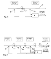
- FIG. 1 the basic principle of the method according to the invention is illustrated in connection with the arrangement according to the invention.
- a thread 1 is passed through a thread guide 2, which the thread 1 in two adjacent sections, in Section a 1 and section a 2 divided, which thus at the same time each section (here initially one-sided) limited.
- a speed sensor 3 and 3a are each arranged before and after the yarn guide element 2, which, based on the respective section, measures the speed v 1 or v 2 of the thread 1. At least the speed sensor 3a measures the speed without contact.
- the measured values or sensor signals for the thread speed are fed to a calculation module 4 or entered into the calculation module, in which further, in particular yarn-related values such as elastic modulus E and thread cross section A 0 , and a calculation rule are already entered and stored or entered and stored there.
- this calculation module 4 is not to be confused with a calculation model.
- a calculation module is a device that executes an invoice according to an already specified calculation rule.
- a computational model is as in the case of the prior art EP 1 473 390 A2 , intangible and only suitable for providing the form of a planned calculation, for example by means of a calculation rule derived from it, in the first place.
- F is henceforth the thread tension in general
- F 1 ... to F ⁇ is the thread tension in the section corresponding to index.
- the thread speed in general is henceforth v; v 1 ... to v ⁇ is the speed in the section corresponding to index.
- Equation (II) is the main calculation rule according to the invention, and preferably this is stored in the calculation module 4 after its input.
- the thread tension F ⁇ before one of the yarn guide elements 2, 2a ... 2 ⁇ -1 given or otherwise known and already entered and stored in the calculation module 4 or is entered and stored there, is as a yarn tension value
- the yarn guide elements are shown schematically as delivery with rotating in the direction of arrow rolls or rollers.
- the corresponding yarn tension value can be determined completely contact-free. If the velocity value v 1 and / or the yarn tension F 1 are not measured without contact, the yarn tension F 2 will nevertheless be the absolute value or the yarn tension value at least the yarn tension ratio F 2 / F 1 , or its reciprocal, in any case with reference to Section a 1 , calculated and can therefore be determined without contact.
- the method includes the further possibility of measuring speed v 2 and yarn tension F 2 in section a 2 once with a contacting method and deriving therefrom a new, simple relationship between force and speed.
- the value dF / dv is given as the differential quotient of equation (II) and by substitution of all known values (F 1 , F 2 , v 1 and v 2 , E and A 0 ).
- FIG. 2 schematically an arrangement is shown, with which a profile of the yarn tension along the thread can be determined.
- the value of the yarn tension F 2 in the adjacent to the yarn guide 2a section a 2 absolute or relative to F 1 can be determined, then it is, by means of the speed sensors 3a and 3b or generally 3 ⁇ -1 and 3 ⁇ , it is possible to determine the yarn tension F 3 (in general F ⁇ ) in the section a 3 (general section a ⁇ ) adjacent to the yarn guide element 2a (generally 2 ⁇ -1 ) in the same way.
- the yarn tension F 2 , F 3 .... F ⁇ are calculated in this way absolutely or at least relative to the yarn tension F 1 .
- the sequence of numbers of these yarn tension values can be represented graphically as a profile according to the invention.
- the two adjacent to a yarn guide elements sensors for example, the Speed sensors 3a and 3b to Fadenleitelement 2a and also, considered at FIG. 2 ,
- the speed sensors 3 ⁇ -1 and 3 ⁇ to Fadenleitelement 2 ⁇ -1 each with a separate computing module 4a and 4 ⁇ in the manner according to FIG. 1 connected.
- all speed sensors 3, 3a .... 3 ⁇ are connected to one and the same computing module 4, with the latter calculating the yarn tension values of all yarn sections a 2 to a ⁇ in this one computing module 4.
- FIG. 3 shows an arrangement for non-contact determination of the absolute yarn tension F 1 in the thread section a.
- the yarn guide element 2 is designed as a controllable delivery mechanism with an upper and a lower roller through which the yarn 1 is driven with the adjustable, that is known, speed v 0 .
- the yarn guide element 2 thus defines the yarn portion a 0 (not provided in the drawing with a reference numeral) as the point at which the thread 1 due to the static friction, the peripheral speed of the rollers, just v 0 , has assumed.
- the thread 1 is drawn off by a subsequent active pairing, not shown, of the textile machine and therefore has a different speed v 1 in section a 1 as v 0 in the delivery plant.
- An electromagnet 5 is connected to the upper roller, so that due to the magnetic force, the upper roller of the roller pair 2 exerts a pressing force on the thread 1, which propagates via the lower roller to a pressure force sensor 6 connected thereto.
- the latter is fixed on a solid surface 7 in its position.
- the pressure force sensor 6 is connected with its output to a controller 8, which in turn feeds the electromagnet 5 with power depending on the pressure force.
- a yarn tension sensor 3 0 connected to the computing module 4 is 0 or optionally combined with the computing module 4 combined Fadenzugkraft- and speed meter 13 or the yarn tension predetermined functional element.
- At least one thread guide element 2, 2a... 2 ⁇ -1 in the vicinity of the thread 1 each has a speed sensor 3, 3a... 3 ⁇ for contactless metrological detection the yarn speed v ⁇ , v ⁇ + 1 arranged.
- Each existing speed sensor 3, 3a... 3 ⁇ is connected to the computing module 4.
- the calculation module 4 are the calculation rule equation (II), the set and thus known speed v 0 and the yarn values A 0 and E already stored.
- the force F 0 is the force acting on the thread in the delivery mechanism as a frictional force, which results from the pressure force and thus adjusted by the controller 8, that can be predetermined, so that it is known.
- the output signal of the controller 8, which is proportional to this force F 0 is accordingly simultaneously supplied to the computing module 4 for the purpose of storage there and inclusion in its calculation (taking into account the proportionality factor between signal value and force F 0 ).
- the computing module 4 is finally supplied with the signal from the non-contact speed sensor 3, so that the computing module 4 thus has all the prerequisites for calculating the absolute value of the yarn tension F 1 in the section a 1 .
- FIG. 4 schematically shows the determination of yarn tension values in the weft insertion in an air-jet loom.
- the thread 1 moves when entering the area of the shed 10 on the speed sensors 3, 3a to 3 generally ⁇ and relay nozzles 12, 12a (not shown: generally 12 ⁇ -1 ) over.
- the relay nozzles 12 and 12a etc. act as yarn guide elements 2, 2a (generally 2 ⁇ ) analog FIG. 2 , They limit the thread 1 sections a 1 , a 2 and generally a ⁇ .
- the yarn tension acting in the yarn can change from one portion to the other.
- the speed sensors 3, 3a to generally 3 ⁇ can preferably after DE 199 00 581 B4 or configured according to the spatial filter method.
- the speed sensors 3, 3a and 3 ⁇ are connected to the computing module 4 leaves itself, as far as the yarn-related values E and A 0 are already stored in the calculation module 4, by means of the likewise stored calculation rule (II), for example from the signals of the speed sensors 3 and 3a, the ratio of the yarn tension F 2 in the section a 2 to the yarn tension F 1 in the section Determine a 1 .
- the ratio of the yarn tension F ⁇ in the section a ⁇ to the yarn tension F 1 in the section a 1 can be determined from the signals of the speed sensors 3 and 3 ⁇ .
- the thread guiding elements 2, 2a ... 2 ⁇ -1 are advantageously to be within the weaving width Stafettendüsen 12, 12a ... 12 ⁇ -1 formed.
- the yarn tension can not be determined anywhere else.
- Fadenzugkraft ratio determined values are related to the (albeit unknown) yarn tension F 1 , these can be used as relative values, in relation to the yarn tension F 1 (possibly in so-called "relative units") be specified.
- the number sequence obtained in this way thus embodies a thread tensile force profile along the thread entered in the area 10 of the shed (general term without graphic representation). Deviations or changes in the thread tension F between the individual sections can be determined. An uneven incorporation can be foreseen.
- the velocity v 0 can also be measured within the main nozzle 11 before the thread 1 leaves the main nozzle 11.
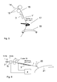
- FIG. 5 schematically shows parts of a ring spinning machine with the inventive arrangement.
- a not yet consolidated sliver 14 in a drafting system 15 leaves this at the location of a so-called spinning triangle 16.
- the then still young thread 1 passes, after a distance, through a spiral thread guide 17 to a zone where the thread 1 is moved in a circle in a circle , He slides on a balloon constriction ring 18 (corresponds to a full circle and is in FIG. 5 only half shown) along. Only by the balloon-shaped circular motion in conjunction with the combination spinning ring / rotor, not shown, the first still unfinished thread 1 'is "twisted" and thus gets its usual strength.
- the contactless speed sensor 3 is arranged in the vicinity of the thread.
- the speed sensor 3 is after DE 199 00 581 B4 carried out according to the spatial filter method and contains as a sensitive part, for example, a curved surface on which the thread 1 would be light and therefore its course then ran slightly curved.
- the speed v 1 in the section 1 detects a.
- the drafting device 15 acts as a yarn guide element 2 and with the thread 1 on the one hand in the section a is 0 (in the drawing, not with a reference numeral provided) at the point where the fiber ribbon has just not yet left 14 the drafting device 15, and the portion of a 1 After the drafting system 15.
- the speed v 0 is known as the delivery speed of the drafting system 15, and because the yarn tension F 0 to the end of the drafting 15 characterized by the mutual friction of the fibers in the sliver 14 is fixed (predetermined), can the yarn tension F 1 in the yarn 1 within the section a 1 by means of the equation (II), analogous as with respect FIG. 3 be explained in the calculation module 4.
- the yarn tension F 1 in the yarn 1 within the section a 1 by means of the equation (II), analogous as with respect FIG. 3 be explained in the calculation module 4.
- At least with the given values E, A 0 and v 0 by an estimate of the constant permanent thread tension F 0 changes .DELTA.F in the desired thread tension F can be quantified with a practice-oriented accuracy.
- FIG. 6 is shown schematically how the yarn tension is measured without contact in a circular knitting machine.
- the thread 1 which is withdrawn from a spool, not shown, first passes a yarn brake 19, for schematic explanation containing a solid surface 7 and a resilient in the vertical direction, therefore adjustable in terms of pressure force cheek 19a.
- the yarn tension F 0 is dependent on the pressure force and is thus set in section a 0 by means of this controlled yarn brake 19; and by means of the contact working tensile force sensor 3 0 is measured.
- This tension sensor 3 0, for example, analogous to the well-known, in FIG. 7 shown, working with contact tensile force sensor 3 0 formed.
- the speed v 0 of the thread 1 in section a 0 is fixed.
- the thread 1 then runs over the section a 1 and the thread guide 20 to a needle contour 21.
- the speed v 1 is measured without contact by means of the contactless speed sensor 3.
- the signals of the speed sensors 3 0 and 3 are supplied to the computing module 4, in which the thread guide element (roller pair) 2 set, and thus known, speed v 0 of the thread 1, the yarn-related values E and A 0 and the calculation rule as an equation (II ) are already stored.
- the absolute value of the yarn tension F 1 in section a 1 is thus determined by the method according to the invention.
- the thread tension in Foumisseur 25 can also be 0. In this case, a tension sensor 3 0 is not required.
- a tensile force sensor 3 0 disposed in the needle bed 21 of a supplied yarn 1 before the yarn guide element. 2 If the yarn guide element 2 is designed as a foisseur 25, the yarn speed v 0 coincides with the delivery speed of the feeder 25 and optionally the yarn tension F 0 is assumed to be "0" in front of or in the foisseur 25.
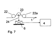
- FIG. 7 shows the schematic diagram of a well-known touch-acting yarn tension sensor.
- the thread 1 is guided by two fixed rollers 22 and 22a and passes between them via a vertically movable roller 23.
- the pressure force sensor 6 includes a deformation body and means for converting its deformation into an output signal.
- the pressure force is proportional to the tensile force F in the yarn 1, and the output signal of the pressure force sensor 6 can be supplied to a computing module 4.
- 3a .... 3 ⁇ for metrological detection of a yarn speed v can each be a sensor according to the laser interference method, the laser Doppler method, preferably the spatial filter method or a correlation method can be used.
Landscapes
- Engineering & Computer Science (AREA)
- Textile Engineering (AREA)
- Physics & Mathematics (AREA)
- General Physics & Mathematics (AREA)
- Force Measurement Appropriate To Specific Purposes (AREA)
- Spinning Or Twisting Of Yarns (AREA)
- Filamentary Materials, Packages, And Safety Devices Therefor (AREA)
Applications Claiming Priority (1)
| Application Number | Priority Date | Filing Date | Title |
|---|---|---|---|
| DE200910030246 DE102009030246B3 (de) | 2009-06-23 | 2009-06-23 | Verfahren und Anordnung zur berührungslosen Bestimmung von Fadenzugkraft-Werten |
Publications (2)
| Publication Number | Publication Date |
|---|---|
| EP2266908A2 true EP2266908A2 (fr) | 2010-12-29 |
| EP2266908A3 EP2266908A3 (fr) | 2011-08-17 |
Family
ID=42797033
Family Applications (1)
| Application Number | Title | Priority Date | Filing Date |
|---|---|---|---|
| EP10006000A Withdrawn EP2266908A3 (fr) | 2009-06-23 | 2010-06-10 | Procédé et dispositif destinés à la détermination sans contact de valeurs de la force de traction de fils |
Country Status (2)
| Country | Link |
|---|---|
| EP (1) | EP2266908A3 (fr) |
| DE (1) | DE102009030246B3 (fr) |
Cited By (4)
| Publication number | Priority date | Publication date | Assignee | Title |
|---|---|---|---|---|
| CN102963770A (zh) * | 2012-12-13 | 2013-03-13 | 杭州电子科技大学 | 一种张力传感信号的iir滤波方法 |
| CN102976156A (zh) * | 2012-12-13 | 2013-03-20 | 杭州电子科技大学 | 一种张力传感信号的fir滤波方法 |
| CN109095280A (zh) * | 2018-09-29 | 2018-12-28 | 中国科学院长春光学精密机械与物理研究所 | 一种导线计米取线装置 |
| CN115607292A (zh) * | 2022-10-18 | 2023-01-17 | 微亚医疗科技(苏州)有限公司 | 导丝递送速度检测装置 |
Families Citing this family (1)
| Publication number | Priority date | Publication date | Assignee | Title |
|---|---|---|---|---|
| DE102017130516A1 (de) | 2017-12-19 | 2019-06-19 | Maschinenfabrik Rieter Ag | Verfahren zur Messung der Zugspannung eines Fadens und Vorrichtung zur Auslenkung eines laufenden Fadens |
Citations (7)
| Publication number | Priority date | Publication date | Assignee | Title |
|---|---|---|---|---|
| EP0753088B1 (fr) | 1994-03-26 | 1997-11-12 | TEMCO TEXTILMASCHINENKOMPONENTEN GmbH & Co. KG | Procede et dispositif pour le controle de files a filaments torsades |
| DE19900581A1 (de) | 1999-01-09 | 2000-07-27 | Univ Dresden Tech | Verfahren, Aufnehmer und Einrichtung zur berührungslosen Bewegungsmessung an einem Faden |
| DE4400037C2 (de) | 1994-01-04 | 2002-12-12 | Wolfgang Schaefer | Winkelmeßeinrichtung, insbesondere für Fadenzugkraftaufnehmer |
| EP1473390A2 (fr) | 2003-04-29 | 2004-11-03 | Sultex AG | Contrôle du transport de fil |
| WO2008012093A2 (fr) | 2006-07-26 | 2008-01-31 | Vienco Gmbh | Procédé et agencement pour déterminer la qualité du fil et/ou la qualité de bobine d'un fil continu à l'aide d'anémometrie laser doppler |
| DE102005038047B4 (de) | 2005-08-10 | 2008-02-07 | Gerhard Schnebel | Fadenspannungssensor |
| EP1953282A1 (fr) | 2007-02-02 | 2008-08-06 | Sultex AG | Procédé et dispositif destinés à l'introduction d'un fil de trame pour une machine à tisser |
Family Cites Families (6)
| Publication number | Priority date | Publication date | Assignee | Title |
|---|---|---|---|---|
| FR2698962B1 (fr) * | 1992-12-07 | 1995-02-10 | Commissariat Energie Atomique | Procédé et dispositif de mesure sans contact de la tension et de la vitesse de défilement d'un fil. |
| US5710432A (en) * | 1996-01-18 | 1998-01-20 | Alcatel Na Cable Systems, Inc. | Non-contact tension measurement of moving fiber using traveling wave time-of-flight analysis |
| US6002472A (en) * | 1997-03-18 | 1999-12-14 | The Furukawa Electric Co., Ltd. | Method of measuring optical fiber drawing tension |
| CN1223833C (zh) * | 2001-02-28 | 2005-10-19 | 古河电气工业株式会社 | 光纤的拉丝张力测定方法 |
| DE10148309A1 (de) * | 2001-09-27 | 2003-02-13 | Dieter Wuestenberg | Verfahren zur Ermittlung der Wickelspannung |
| DE10210911A1 (de) * | 2002-03-04 | 2003-09-18 | Picanol Nv | Vorrichtung zum Erfassen und/oder Einstellen einer Zugkraft in einem Faden |
-
2009
- 2009-06-23 DE DE200910030246 patent/DE102009030246B3/de not_active Expired - Fee Related
-
2010
- 2010-06-10 EP EP10006000A patent/EP2266908A3/fr not_active Withdrawn
Patent Citations (8)
| Publication number | Priority date | Publication date | Assignee | Title |
|---|---|---|---|---|
| DE4400037C2 (de) | 1994-01-04 | 2002-12-12 | Wolfgang Schaefer | Winkelmeßeinrichtung, insbesondere für Fadenzugkraftaufnehmer |
| EP0753088B1 (fr) | 1994-03-26 | 1997-11-12 | TEMCO TEXTILMASCHINENKOMPONENTEN GmbH & Co. KG | Procede et dispositif pour le controle de files a filaments torsades |
| DE19900581A1 (de) | 1999-01-09 | 2000-07-27 | Univ Dresden Tech | Verfahren, Aufnehmer und Einrichtung zur berührungslosen Bewegungsmessung an einem Faden |
| DE19900581B4 (de) | 1999-01-09 | 2005-12-22 | Technische Universität Dresden | Verfahren und Schaltungsanordnung zur berührungslosen Bewegungsmessung an einem Faden |
| EP1473390A2 (fr) | 2003-04-29 | 2004-11-03 | Sultex AG | Contrôle du transport de fil |
| DE102005038047B4 (de) | 2005-08-10 | 2008-02-07 | Gerhard Schnebel | Fadenspannungssensor |
| WO2008012093A2 (fr) | 2006-07-26 | 2008-01-31 | Vienco Gmbh | Procédé et agencement pour déterminer la qualité du fil et/ou la qualité de bobine d'un fil continu à l'aide d'anémometrie laser doppler |
| EP1953282A1 (fr) | 2007-02-02 | 2008-08-06 | Sultex AG | Procédé et dispositif destinés à l'introduction d'un fil de trame pour une machine à tisser |
Cited By (4)
| Publication number | Priority date | Publication date | Assignee | Title |
|---|---|---|---|---|
| CN102963770A (zh) * | 2012-12-13 | 2013-03-13 | 杭州电子科技大学 | 一种张力传感信号的iir滤波方法 |
| CN102976156A (zh) * | 2012-12-13 | 2013-03-20 | 杭州电子科技大学 | 一种张力传感信号的fir滤波方法 |
| CN109095280A (zh) * | 2018-09-29 | 2018-12-28 | 中国科学院长春光学精密机械与物理研究所 | 一种导线计米取线装置 |
| CN115607292A (zh) * | 2022-10-18 | 2023-01-17 | 微亚医疗科技(苏州)有限公司 | 导丝递送速度检测装置 |
Also Published As
| Publication number | Publication date |
|---|---|
| EP2266908A3 (fr) | 2011-08-17 |
| DE102009030246B3 (de) | 2010-12-30 |
Similar Documents
| Publication | Publication Date | Title |
|---|---|---|
| EP1454133B1 (fr) | Utilisation de micro-ondes dans l'industrie de la filature | |
| EP2112258B1 (fr) | Dispositif et procédé d'enroulement d'une mèche sur une bobine | |
| DE102007039067A1 (de) | Vorrichtung an einer Kämmmaschine zur Überwachung des Kämmlingsanteils | |
| EP1101846B1 (fr) | Dispositif de rattache containant un dispositif d'evaluation des paramètres d'une procedure de rattachement automatique | |
| DE102009030246B3 (de) | Verfahren und Anordnung zur berührungslosen Bestimmung von Fadenzugkraft-Werten | |
| EP2915910B1 (fr) | Procédé et dispositif de fonctionnement d'un métier à filer à rotor | |
| EP1350870A2 (fr) | Appareil et procédé pour optimaliser des valeurs de réglage d'une machine de filature | |
| DE19615947B4 (de) | Minimalwert-suchende Regulierungsoptimierung | |
| DE102008049363A1 (de) | Vorrichtung für eine oder an einer Spinnereivorbereitungsmaschine, die ein Streckwerk zum Verstrecken von strangförmigem Fasermaterial aufweist | |
| CH708290A2 (de) | Wickelmaschine und Verfahren zum Wickeln von Watte aus Faserbändern. | |
| EP1960574B1 (fr) | Procede pour rattacher un fil ainsi que machine de filature a rotor pour la mise en uvre du procede | |
| DE10140645A1 (de) | Verfahren zum Betreiben eines Streckwerks sowie Streckwerk | |
| EP1685054B1 (fr) | Nettoyeur de file | |
| DE102008008083A1 (de) | Verfahren und Vorrichtung zum Herstellen von Kreuzwickelspulen | |
| DE10059262A1 (de) | Verfahren zur Optimierung der Regelung und Steuerung von Verzugseinrichtungen an Spinnereimaschinen | |
| DE102005019760B4 (de) | Spinnereimaschine mit einem Streckwerk zum Verstrecken eines Faserverbandes und entsprechendes Verfahren | |
| DE102008038392A1 (de) | Vorrichtung für eine oder an einer Spinnereivorbereitungsmaschine, die ein Streckwerk zum Verstrecken von strangförmigem Fasermaterial aufweist | |
| WO2013156320A1 (fr) | Unité fonctionnelle d'une zone de bobinage comportant un dispositif d'épissage de fil et un nettoyeur de filé | |
| EP1709222B1 (fr) | Procede pour produire un file fantaisie | |
| DE10227676A1 (de) | Verfahren und Vorrichtung zur Auswertung von Signalen eines Sensors | |
| DE4124626C2 (de) | Vorrichtung zur Messung der Windungszahl und/oder der Knoten bzw. Fadendicken von textilen Fäden | |
| EP4274926A1 (fr) | Procédé de détermination de la quantité de blousse sur une peigneuse et peigneuse | |
| DE3719281A1 (de) | Verfahren und vorrichtung zum erzeugen von jeweils zwei fadenkomponenten | |
| DE9110398U1 (de) | Vorrichtung zum Messen der Wickeldicke von Fäden | |
| DE19547544A1 (de) | Verfahren zum Überprüfen des Fadenprofils |
Legal Events
| Date | Code | Title | Description |
|---|---|---|---|
| PUAI | Public reference made under article 153(3) epc to a published international application that has entered the european phase |
Free format text: ORIGINAL CODE: 0009012 |
|
| AK | Designated contracting states |
Kind code of ref document: A2 Designated state(s): AL AT BE BG CH CY CZ DE DK EE ES FI FR GB GR HR HU IE IS IT LI LT LU LV MC MK MT NL NO PL PT RO SE SI SK SM TR |
|
| AX | Request for extension of the european patent |
Extension state: BA ME RS |
|
| PUAL | Search report despatched |
Free format text: ORIGINAL CODE: 0009013 |
|
| AK | Designated contracting states |
Kind code of ref document: A3 Designated state(s): AL AT BE BG CH CY CZ DE DK EE ES FI FR GB GR HR HU IE IS IT LI LT LU LV MC MK MT NL NO PL PT RO SE SI SK SM TR |
|
| AX | Request for extension of the european patent |
Extension state: BA ME RS |
|
| RIC1 | Information provided on ipc code assigned before grant |
Ipc: D03D 47/30 20060101ALI20110713BHEP Ipc: G01L 5/10 20060101ALI20110713BHEP Ipc: B65H 61/00 20060101ALI20110713BHEP Ipc: B65H 59/40 20060101AFI20110713BHEP |
|
| 17P | Request for examination filed |
Effective date: 20111216 |
|
| 17Q | First examination report despatched |
Effective date: 20120904 |
|
| STAA | Information on the status of an ep patent application or granted ep patent |
Free format text: STATUS: THE APPLICATION IS DEEMED TO BE WITHDRAWN |
|
| 18D | Application deemed to be withdrawn |
Effective date: 20130103 |