EP2266916A2 - Korkenzieher - Google Patents
Korkenzieher Download PDFInfo
- Publication number
- EP2266916A2 EP2266916A2 EP10155163A EP10155163A EP2266916A2 EP 2266916 A2 EP2266916 A2 EP 2266916A2 EP 10155163 A EP10155163 A EP 10155163A EP 10155163 A EP10155163 A EP 10155163A EP 2266916 A2 EP2266916 A2 EP 2266916A2
- Authority
- EP
- European Patent Office
- Prior art keywords
- assembly
- screw
- shaped
- link
- driven link
- Prior art date
- Legal status (The legal status is an assumption and is not a legal conclusion. Google has not performed a legal analysis and makes no representation as to the accuracy of the status listed.)
- Granted
Links
- 238000005096 rolling process Methods 0.000 claims description 15
- ATJFFYVFTNAWJD-UHFFFAOYSA-N Tin Chemical compound [Sn] ATJFFYVFTNAWJD-UHFFFAOYSA-N 0.000 claims description 5
- 239000007799 cork Substances 0.000 abstract description 5
- 238000005516 engineering process Methods 0.000 description 3
- 238000007789 sealing Methods 0.000 description 3
- 230000003247 decreasing effect Effects 0.000 description 1
- 230000007547 defect Effects 0.000 description 1
- 230000000593 degrading effect Effects 0.000 description 1
- 230000002349 favourable effect Effects 0.000 description 1
- 238000000034 method Methods 0.000 description 1
- 239000002023 wood Substances 0.000 description 1
Images



Classifications
-
- B—PERFORMING OPERATIONS; TRANSPORTING
- B67—OPENING, CLOSING OR CLEANING BOTTLES, JARS OR SIMILAR CONTAINERS; LIQUID HANDLING
- B67B—APPLYING CLOSURE MEMBERS TO BOTTLES JARS, OR SIMILAR CONTAINERS; OPENING CLOSED CONTAINERS
- B67B7/00—Hand- or power-operated devices for opening closed containers
- B67B7/02—Hand- or power-operated devices for opening closed containers for removing stoppers
- B67B7/04—Cork-screws
- B67B7/0417—Cork-screws with supporting means for assisting the pulling action
- B67B7/0447—Cork-screws with supporting means for assisting the pulling action whereby the supporting means abut around parts of the periphery of the neck of the bottle
Definitions
- the present invention relates to a corkscrew used for opening wood corks and plastic corks of wine bottles.
- the corkscrew for opening wine bottle corks with the existing technology comprises a tubular body with openings on both ends, gear driving mechanism set inside the tubular body, screw assembly, screw guiding assembly for screw of the screw assembly to pass through, elastic limit piece, and actuation lever on the top of the tubular body and capping assembly at the bottom of the tubular body respectively, the screw guiding assembly is slide-fitted in the tubular body;
- the capping assembly is set on the inner wall of the tubular body, which forms a shape matching the shape of the neck of bottle;
- the elastic limit piece is installed between the tubular body and the capping assembly, the elastic limit piece can prop up the neck of bottle so as to limit the axial sliding of screw guiding assembly;
- the gear driving mechanism includes gear, rack set on the inner wall of the tubular body and engaged with the gear, and U-shaped connector for connecting screw, the actuation lever is welded on one point of the outer circumferential surface of the gear, and fit for the gear in a rolling way through the shaft in the central hole
- the abovementioned corkscrew adopts a gear-driving mechanism.
- the corks for sealing wine bottles can be opened, but the following shortcomings still exist when using it in our daily life: 1.
- the stroke of gear driving mechanism is the length of rack, the length limits the length for the screw to insert and pull out the corks and the operation handle of the gear driving mechanism can only drive the screw to make one-direction movement during its movement, so the aforesaid corkscrew requires rotating the actuation lever back and forth twice during application to pull out corks from wine bottles and remove the corks on the screw, not only leading to inconvenient operation, but also wasting more time and strength when rotating the lever twice back and forth, thus adding more burden on the person for opening bottles; 2.
- the present invention addresses the technical problem, through overcoming the abovementioned defects of the existing technology, by means of providing a timesaving corkscrew with the least resistance and convenience for operation.
- the technical solution of the present invention is to provide a corkscrew which comprises a tubular body with opening on both ends, driving mechanism set inside the tubular body, screw assembly, screw guiding assembly for screw of the screw assembly to pass through, elastic limit piece, and actuation lever on the top of the tubular body and capping assembly at the bottom of the tubular body respectively, wherein the driving link of the driving mechanism is connected with the actuation lever, the driven link is connected with the screw assembly; the screw guiding assembly is slide-fitted in the tubular body; the capping assembly is set on the inner wall of the tubular body, which forms a shape matching the shape of the neck of bottle; the elastic limit piece is installed between the tubular body and the capping assembly, the elastic limit piece can prop up the neck of bottle so as to limit the axial sliding of screw guiding assembly, the driving mechanism is a linkage driving mechanism.
- the present invention After adopting the abovementioned structure, comparing with the existing technology, the present invention has the following favorable effects:
- a rolling cutter is set on the capping assembly for the present invention, tinfoil for externally sealing the bottle can be easily removed through rotating the bottle, so as to improve the practicability of the present invention.
- a rolling wheel is set on the capping assembly for the present invention; the bottle is roll-fitted with the rolling wheel, so the corkscrew for the present invention can easily remove the tinfoil for externally sealing the bottle, thus the corkscrew for the present invention is very convenient for utilization.
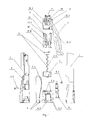
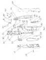
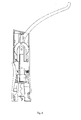
- a corkscrew disclosed by the present invention comprises a tubular body 1 with opening on both ends, linkage driving mechanism set inside the tubular body 1, screw assembly 2, screw guiding assembly 3 for screw 2.2 of the screw assembly 2 to pass through, elastic limit piece 8, and actuation lever 5 on the top of the tubular body and capping assembly 6 at the bottom of the tubular body respectively, wherein the driving link of the driving mechanism is connected with the lever 5, the driven link is connected with the screw 2; the screw guiding assembly 3 is slide-fitted onto the groove of the tubular body 1 (not shown in the figure); the capping assembly 6 is set on the inner wall of the tubular body 1, which forms a shape matching the shape of the neck of bottle 7; the elastic limit piece 8 is installed between the tubular body1 and the capping assembly 6, the elastic limit piece 8 can prop up the neck of bottle 7 so as to limit the axial sliding of screw guiding assembly 3, the tabular body 1 with opening on both ends is fixedly connected through screw 1.3 from the left body
- the linkage driving mechanism includes the driving wheel 9, connecting rod 10, shaft 11 passing through the center of the circle of the driving wheel 9, U-shaped connector 12, connecting link 13 and U-shaped driven link 14, wherein the driving link of the driving wheel 9 linkage driving mechanism, the driven link of the linkage driving mechanism is U-shaped driven link 14, the lever 5 is welded on the driving wheel 9, the screw assembly 2 is fixed on the bottom of the U-shaped driven link 14 by bolts.
- the hinge point of the driving wheel 9 and connecting rod 10 the hinge point of the driving wheel 9 and U-shaped connector 12, and that of the driving wheel 9 and the connecting link 13 are on the same central line of the driving wheel 9.
- connection rod 10 is pivotally associated to the driving wheel 9 and the other end of the connecting rod 10 is pivotally associated to the tabular body 1, which indicates that: there are two connecting rods 10, one side of the two connecting rods 10 is connected with the tabular body 1 through the bolt gasket 10.1 respectively, and the connecting rod 10 can rotate-fitted on the bolts of the bolt gasket; a shaft one 10.2 is set on the edge part of the both sides of the driving wheel, the other side of the two connecting rods is pivotally associated to the both sides of the shaft one 10.2, and axially limits the shaft one 10.2 through the clamp spring 10.3.
- a circumferential groove One 9.1 is set on the circumferential surface of the driving wheel 9; one end of the connecting link 13 is placed in the groove One 9.1 and pivotally associated to the driving wheel 9, the other end of the connecting link 13 is placed in the U-shaped groove of the U-shaped driven link 14 and pivotally associated to the U-shaped driven link 14; the shaft 11 passes through the two supporting rods of the U-shaped connector opening end 12.1 and is hinged on to the both ends of the shaft 11.
- the three hinge points of the driving wheel 9 are on the same diameter, namely, shaft 11, shaft One 10.2 and shaft Two 13.1 are on the same plane.
- the U-shaped driven link 14 is slide-fitted with the U-shaped connector 12, which indicates that: slideways 12.3 are set outside of the two supporting rods of the U-shaped connector opening end 12.1, the two supporting rods of the U-shaped driven link opening end 14.1 is slide-fitted into the two slideways 12.3.
- the U-shaped connector 12 and u-shaped driven link 14 are slide-fitted onto the tabular body 1, which indicates that: an axial groove 4 is set on the inner wall of the tabular body 1, the two supporting rods of the U-shaped connector opening end 12.1 are slide-fitted inside the groove 4, the two supporting rods of the U-shaped driven link opening end 14.1 are slide-fitted outside the groove 4.
- the capping assembly is composed of the capping handle 6.1 and capping piece 6.2, wherein at least one rolling wheel 6.3 is set on the capping handle 6.1 and connected onto the inner wall of the capping handle 6.1 body through the shaft; at least four rectangular-arranged rolling wheels 6.3 are installed on the inner wall of the capping piece 6.2 and connected onto the inner wall of the capping piece 6.2 through the shaft; the capping assembly 6 is set on the inner wall of the tabular body 1, which forms an internal shape matching the shape of the neck of bottle 7, the capping assembly 6 can be roll-fitted with the bottle 7; the axis of the rolling wheel 6.3 is parallel to that of the tabular body 1; at least one rolling cutter 6.4 for cutting off the tinfoil of bottle is set on the inner wall of the capping assembly 6, the axis of the rolling cutter 6.4 is parallel to that of the tabular body 1.
- the screw assembly 2 includes connector 2.1, screw 2.2 and bolt 2.3, wherein a through hole 2.4 matching the shape of the bolt is set in the connector 2.1, the bolt 2.3 is slide-fitted with the through hole 2.4 and fitted with the shaft; the thread end of the bolt 2.3 is fixed connected with the end away from the head of the screw 2.2; the connector 2.1 is fixedly connected with the bottom of the U-shaped driven link 14.
- a elastic limit piece 8 supported and pushed by the neck of bottle 7 is set between the tabular body 1 and the capping assembly 6, the structure is detailed as below: a elastic limit piece 8 is set between the inner wall of the tabular body 1 and the capping assembly 6, the middle part of the elastic limit piece 8 is a protrusion 8.1 against the neck of bottle, wherein the height of the protrusion 8.1 is more than the thickness of the capping assembly 1; one side of the elastic limit piece 8 is pivotally associated to the tabular body 1, the other side of a spring 8.2 props up the tabular body, a groove is set on the inner wall of the tabular body to radially limit the spring 8.2, the other side is provided with a U-shaped hook 8.3 which (8.3) axially limits the screw guiding assembly 3; when the bottle 7 is place inside, the neck of the bottle supports and pushes the protrusion 8.1 so as to drive the hook to move towards the tabular body 1; when the bottle 7 is taken out, it is reset by means of the spring 8.2, the hook 8.3
- the screw guiding assembly 3 consists of the upper connector 3.1, the guiding piece 3.2 and the lower connector 3.3, wherein the guiding piece 3.2 is composed of two small-diameter columns set on both ends of a large-diameter column respectively; the guiding piece 3.2 is provided with an axial spiral channel 3.4 matching the shape of the screw 2.2; a hole 3.5 slide-fitted with the guiding piece 3.2 is set in the body composed of the upper connector 3.1 and the lower connector 3.3; the both ends of the guiding piece 3.2 extend out over the bodys of the upper connector 3.1 and the lower connector 3.3 respectively and play the role of radial limitation through the abovementioned two connectors, mutually engaged one-way teeth 3.6 are set on the one ladder end face of the guiding piece 3.2 and the end face of the lower connector 3.3 against the ladder end face, wherein the one-way tooth 3.6 has a vertical side and a inclined side, when the guiding piece 3.2 and the lower connector 3.3 rotate anticlockwise, two vertical surfaces contact
Landscapes
- Engineering & Computer Science (AREA)
- Mechanical Engineering (AREA)
- Devices For Opening Bottles Or Cans (AREA)
Applications Claiming Priority (1)
| Application Number | Priority Date | Filing Date | Title |
|---|---|---|---|
| CN2009101001829A CN101613070B (zh) | 2009-06-26 | 2009-06-26 | 开瓶器 |
Publications (3)
| Publication Number | Publication Date |
|---|---|
| EP2266916A2 true EP2266916A2 (de) | 2010-12-29 |
| EP2266916A3 EP2266916A3 (de) | 2013-02-20 |
| EP2266916B1 EP2266916B1 (de) | 2014-06-25 |
Family
ID=41492984
Family Applications (1)
| Application Number | Title | Priority Date | Filing Date |
|---|---|---|---|
| EP20100155163 Not-in-force EP2266916B1 (de) | 2009-06-26 | 2010-03-02 | Korkenzieher |
Country Status (2)
| Country | Link |
|---|---|
| EP (1) | EP2266916B1 (de) |
| CN (1) | CN101613070B (de) |
Cited By (1)
| Publication number | Priority date | Publication date | Assignee | Title |
|---|---|---|---|---|
| CN102452632A (zh) * | 2011-10-21 | 2012-05-16 | 珠海市科力通电器有限公司 | 一种全自动红酒开瓶器 |
Families Citing this family (2)
| Publication number | Priority date | Publication date | Assignee | Title |
|---|---|---|---|---|
| CN104229697B (zh) * | 2014-09-03 | 2016-04-20 | 珠海市香之君科技股份有限公司 | 电动开瓶组合 |
| CN104909315A (zh) * | 2015-04-28 | 2015-09-16 | 尚平 | 一种开瓶器 |
Family Cites Families (7)
| Publication number | Priority date | Publication date | Assignee | Title |
|---|---|---|---|---|
| EP0023858B1 (de) * | 1979-08-02 | 1986-11-05 | Prevost, Anne-Marie (née Richard) | Korkenzieher mit Flaschenzugübersetzung |
| DE20219538U1 (de) * | 2002-12-16 | 2003-03-13 | WARBEG Warenbeschaffungs-GmbH, 45131 Essen | Korkenzieher |
| GB2399566B (en) * | 2003-03-19 | 2005-08-24 | Technical Dev | Corkscrew |
| DE102004016753B4 (de) * | 2004-04-06 | 2020-07-23 | Medvetskiy Oleksandr | Vorrichtung und Verfahren zum Entfernen eines Korkens aus einem Flaschenhals |
| US7069825B2 (en) * | 2004-11-26 | 2006-07-04 | Technical Development (Hk) Limited | Corkscrew |
| CN2868979Y (zh) * | 2005-11-16 | 2007-02-14 | 周建华 | 开瓶器 |
| CN201439489U (zh) * | 2009-06-26 | 2010-04-21 | 宁波市佳利来机械制造有限公司 | 开瓶器 |
-
2009
- 2009-06-26 CN CN2009101001829A patent/CN101613070B/zh not_active Expired - Fee Related
-
2010
- 2010-03-02 EP EP20100155163 patent/EP2266916B1/de not_active Not-in-force
Non-Patent Citations (1)
| Title |
|---|
| None |
Cited By (2)
| Publication number | Priority date | Publication date | Assignee | Title |
|---|---|---|---|---|
| CN102452632A (zh) * | 2011-10-21 | 2012-05-16 | 珠海市科力通电器有限公司 | 一种全自动红酒开瓶器 |
| CN102452632B (zh) * | 2011-10-21 | 2013-03-27 | 珠海市科力通电器有限公司 | 一种全自动红酒开瓶器 |
Also Published As
| Publication number | Publication date |
|---|---|
| EP2266916B1 (de) | 2014-06-25 |
| CN101613070B (zh) | 2011-05-18 |
| CN101613070A (zh) | 2009-12-30 |
| EP2266916A3 (de) | 2013-02-20 |
Similar Documents
| Publication | Publication Date | Title |
|---|---|---|
| CN110734022B (zh) | 一种罐头开封用起盖器及其使用方法 | |
| CN208408940U (zh) | 全自动压装氩焊装置 | |
| CN111573584A (zh) | 一种按压式罐头开盖装置及方法 | |
| EP2266916B1 (de) | Korkenzieher | |
| CN201439489U (zh) | 开瓶器 | |
| CN208413797U (zh) | 一种开瓶器 | |
| CN210354370U (zh) | 一种用于饮水机的桶装水更换装置 | |
| CN1993291B (zh) | 改进的墙壁安装开塞钻 | |
| CN208214810U (zh) | 一种用于车床加工的锁紧装置 | |
| CN101985863A (zh) | 一种窗把手 | |
| CN201095588Y (zh) | 免握持省力木塞瓶开瓶器 | |
| CN210133315U (zh) | 一种涂料桶压盖设备 | |
| CN104211002B (zh) | 一种具有旋转轴及轮毂和手柄的手动开罐器 | |
| CN2900088Y (zh) | 一种组合式棘轮螺丝刀 | |
| CN201433084Y (zh) | 压转式启瓶器 | |
| CN203127066U (zh) | 自行车伸缩管件防扭转装置 | |
| CN106638913B (zh) | 一种设有多层池壁的储水池 | |
| CN210764240U (zh) | 一种用于软木塞的启瓶器 | |
| US7287446B2 (en) | Rack and pinion bottle opener with insert | |
| CN115504418B (zh) | 一种旋盖装置 | |
| CN117086905A (zh) | 瓶盖预扭机械手及方法 | |
| CN201689197U (zh) | 光缆的联接插头装置 | |
| CN215287919U (zh) | 五加仑桶旋盖装置 | |
| CN203441249U (zh) | 螺旋启闭闭锁 | |
| CN218294665U (zh) | 一种具有安装定位结构的蝶阀 |
Legal Events
| Date | Code | Title | Description |
|---|---|---|---|
| PUAI | Public reference made under article 153(3) epc to a published international application that has entered the european phase |
Free format text: ORIGINAL CODE: 0009012 |
|
| AK | Designated contracting states |
Kind code of ref document: A2 Designated state(s): AT BE BG CH CY CZ DE DK EE ES FI FR GB GR HR HU IE IS IT LI LT LU LV MC MK MT NL NO PL PT RO SE SI SK SM TR |
|
| PUAL | Search report despatched |
Free format text: ORIGINAL CODE: 0009013 |
|
| AK | Designated contracting states |
Kind code of ref document: A3 Designated state(s): AT BE BG CH CY CZ DE DK EE ES FI FR GB GR HR HU IE IS IT LI LT LU LV MC MK MT NL NO PL PT RO SE SI SK SM TR |
|
| RIC1 | Information provided on ipc code assigned before grant |
Ipc: B67B 7/04 20060101AFI20130117BHEP |
|
| 17P | Request for examination filed |
Effective date: 20130531 |
|
| RBV | Designated contracting states (corrected) |
Designated state(s): AT BE BG CH CY CZ DE DK EE ES FI FR GB GR HR HU IE IS IT LI LT LU LV MC MK MT NL NO PL PT RO SE SI SK SM TR |
|
| GRAP | Despatch of communication of intention to grant a patent |
Free format text: ORIGINAL CODE: EPIDOSNIGR1 |
|
| INTG | Intention to grant announced |
Effective date: 20131204 |
|
| GRAS | Grant fee paid |
Free format text: ORIGINAL CODE: EPIDOSNIGR3 |
|
| GRAA | (expected) grant |
Free format text: ORIGINAL CODE: 0009210 |
|
| AK | Designated contracting states |
Kind code of ref document: B1 Designated state(s): AT BE BG CH CY CZ DE DK EE ES FI FR GB GR HR HU IE IS IT LI LT LU LV MC MK MT NL NO PL PT RO SE SI SK SM TR |
|
| REG | Reference to a national code |
Ref country code: GB Ref legal event code: FG4D |
|
| REG | Reference to a national code |
Ref country code: CH Ref legal event code: EP |
|
| REG | Reference to a national code |
Ref country code: AT Ref legal event code: REF Ref document number: 674541 Country of ref document: AT Kind code of ref document: T Effective date: 20140715 |
|
| REG | Reference to a national code |
Ref country code: IE Ref legal event code: FG4D |
|
| REG | Reference to a national code |
Ref country code: DE Ref legal event code: R096 Ref document number: 602010016928 Country of ref document: DE Effective date: 20140807 |
|
| PG25 | Lapsed in a contracting state [announced via postgrant information from national office to epo] |
Ref country code: NO Free format text: LAPSE BECAUSE OF FAILURE TO SUBMIT A TRANSLATION OF THE DESCRIPTION OR TO PAY THE FEE WITHIN THE PRESCRIBED TIME-LIMIT Effective date: 20140925 Ref country code: LT Free format text: LAPSE BECAUSE OF FAILURE TO SUBMIT A TRANSLATION OF THE DESCRIPTION OR TO PAY THE FEE WITHIN THE PRESCRIBED TIME-LIMIT Effective date: 20140625 Ref country code: GR Free format text: LAPSE BECAUSE OF FAILURE TO SUBMIT A TRANSLATION OF THE DESCRIPTION OR TO PAY THE FEE WITHIN THE PRESCRIBED TIME-LIMIT Effective date: 20140926 Ref country code: FI Free format text: LAPSE BECAUSE OF FAILURE TO SUBMIT A TRANSLATION OF THE DESCRIPTION OR TO PAY THE FEE WITHIN THE PRESCRIBED TIME-LIMIT Effective date: 20140625 Ref country code: CY Free format text: LAPSE BECAUSE OF FAILURE TO SUBMIT A TRANSLATION OF THE DESCRIPTION OR TO PAY THE FEE WITHIN THE PRESCRIBED TIME-LIMIT Effective date: 20140625 |
|
| REG | Reference to a national code |
Ref country code: AT Ref legal event code: MK05 Ref document number: 674541 Country of ref document: AT Kind code of ref document: T Effective date: 20140625 |
|
| REG | Reference to a national code |
Ref country code: NL Ref legal event code: VDEP Effective date: 20140625 |
|
| REG | Reference to a national code |
Ref country code: LT Ref legal event code: MG4D |
|
| PG25 | Lapsed in a contracting state [announced via postgrant information from national office to epo] |
Ref country code: LV Free format text: LAPSE BECAUSE OF FAILURE TO SUBMIT A TRANSLATION OF THE DESCRIPTION OR TO PAY THE FEE WITHIN THE PRESCRIBED TIME-LIMIT Effective date: 20140625 Ref country code: SE Free format text: LAPSE BECAUSE OF FAILURE TO SUBMIT A TRANSLATION OF THE DESCRIPTION OR TO PAY THE FEE WITHIN THE PRESCRIBED TIME-LIMIT Effective date: 20140625 Ref country code: HR Free format text: LAPSE BECAUSE OF FAILURE TO SUBMIT A TRANSLATION OF THE DESCRIPTION OR TO PAY THE FEE WITHIN THE PRESCRIBED TIME-LIMIT Effective date: 20140625 |
|
| PG25 | Lapsed in a contracting state [announced via postgrant information from national office to epo] |
Ref country code: RO Free format text: LAPSE BECAUSE OF FAILURE TO SUBMIT A TRANSLATION OF THE DESCRIPTION OR TO PAY THE FEE WITHIN THE PRESCRIBED TIME-LIMIT Effective date: 20140625 Ref country code: ES Free format text: LAPSE BECAUSE OF FAILURE TO SUBMIT A TRANSLATION OF THE DESCRIPTION OR TO PAY THE FEE WITHIN THE PRESCRIBED TIME-LIMIT Effective date: 20140625 Ref country code: CZ Free format text: LAPSE BECAUSE OF FAILURE TO SUBMIT A TRANSLATION OF THE DESCRIPTION OR TO PAY THE FEE WITHIN THE PRESCRIBED TIME-LIMIT Effective date: 20140625 Ref country code: SK Free format text: LAPSE BECAUSE OF FAILURE TO SUBMIT A TRANSLATION OF THE DESCRIPTION OR TO PAY THE FEE WITHIN THE PRESCRIBED TIME-LIMIT Effective date: 20140625 Ref country code: PT Free format text: LAPSE BECAUSE OF FAILURE TO SUBMIT A TRANSLATION OF THE DESCRIPTION OR TO PAY THE FEE WITHIN THE PRESCRIBED TIME-LIMIT Effective date: 20141027 Ref country code: EE Free format text: LAPSE BECAUSE OF FAILURE TO SUBMIT A TRANSLATION OF THE DESCRIPTION OR TO PAY THE FEE WITHIN THE PRESCRIBED TIME-LIMIT Effective date: 20140625 |
|
| PG25 | Lapsed in a contracting state [announced via postgrant information from national office to epo] |
Ref country code: NL Free format text: LAPSE BECAUSE OF FAILURE TO SUBMIT A TRANSLATION OF THE DESCRIPTION OR TO PAY THE FEE WITHIN THE PRESCRIBED TIME-LIMIT Effective date: 20140625 Ref country code: PL Free format text: LAPSE BECAUSE OF FAILURE TO SUBMIT A TRANSLATION OF THE DESCRIPTION OR TO PAY THE FEE WITHIN THE PRESCRIBED TIME-LIMIT Effective date: 20140625 Ref country code: AT Free format text: LAPSE BECAUSE OF FAILURE TO SUBMIT A TRANSLATION OF THE DESCRIPTION OR TO PAY THE FEE WITHIN THE PRESCRIBED TIME-LIMIT Effective date: 20140625 Ref country code: IS Free format text: LAPSE BECAUSE OF FAILURE TO SUBMIT A TRANSLATION OF THE DESCRIPTION OR TO PAY THE FEE WITHIN THE PRESCRIBED TIME-LIMIT Effective date: 20141025 |
|
| REG | Reference to a national code |
Ref country code: DE Ref legal event code: R097 Ref document number: 602010016928 Country of ref document: DE |
|
| PG25 | Lapsed in a contracting state [announced via postgrant information from national office to epo] |
Ref country code: IT Free format text: LAPSE BECAUSE OF FAILURE TO SUBMIT A TRANSLATION OF THE DESCRIPTION OR TO PAY THE FEE WITHIN THE PRESCRIBED TIME-LIMIT Effective date: 20140625 Ref country code: DK Free format text: LAPSE BECAUSE OF FAILURE TO SUBMIT A TRANSLATION OF THE DESCRIPTION OR TO PAY THE FEE WITHIN THE PRESCRIBED TIME-LIMIT Effective date: 20140625 |
|
| PLBE | No opposition filed within time limit |
Free format text: ORIGINAL CODE: 0009261 |
|
| STAA | Information on the status of an ep patent application or granted ep patent |
Free format text: STATUS: NO OPPOSITION FILED WITHIN TIME LIMIT |
|
| 26N | No opposition filed |
Effective date: 20150326 |
|
| PG25 | Lapsed in a contracting state [announced via postgrant information from national office to epo] |
Ref country code: BE Free format text: LAPSE BECAUSE OF FAILURE TO SUBMIT A TRANSLATION OF THE DESCRIPTION OR TO PAY THE FEE WITHIN THE PRESCRIBED TIME-LIMIT Effective date: 20140625 |
|
| REG | Reference to a national code |
Ref country code: DE Ref legal event code: R119 Ref document number: 602010016928 Country of ref document: DE |
|
| PG25 | Lapsed in a contracting state [announced via postgrant information from national office to epo] |
Ref country code: LU Free format text: LAPSE BECAUSE OF FAILURE TO SUBMIT A TRANSLATION OF THE DESCRIPTION OR TO PAY THE FEE WITHIN THE PRESCRIBED TIME-LIMIT Effective date: 20150302 Ref country code: MC Free format text: LAPSE BECAUSE OF FAILURE TO SUBMIT A TRANSLATION OF THE DESCRIPTION OR TO PAY THE FEE WITHIN THE PRESCRIBED TIME-LIMIT Effective date: 20140625 |
|
| REG | Reference to a national code |
Ref country code: CH Ref legal event code: PL |
|
| GBPC | Gb: european patent ceased through non-payment of renewal fee |
Effective date: 20150302 |
|
| PG25 | Lapsed in a contracting state [announced via postgrant information from national office to epo] |
Ref country code: SI Free format text: LAPSE BECAUSE OF FAILURE TO SUBMIT A TRANSLATION OF THE DESCRIPTION OR TO PAY THE FEE WITHIN THE PRESCRIBED TIME-LIMIT Effective date: 20140625 |
|
| REG | Reference to a national code |
Ref country code: FR Ref legal event code: ST Effective date: 20151130 |
|
| REG | Reference to a national code |
Ref country code: IE Ref legal event code: MM4A |
|
| PG25 | Lapsed in a contracting state [announced via postgrant information from national office to epo] |
Ref country code: DE Free format text: LAPSE BECAUSE OF NON-PAYMENT OF DUE FEES Effective date: 20151001 Ref country code: IE Free format text: LAPSE BECAUSE OF NON-PAYMENT OF DUE FEES Effective date: 20150302 Ref country code: CH Free format text: LAPSE BECAUSE OF NON-PAYMENT OF DUE FEES Effective date: 20150331 Ref country code: GB Free format text: LAPSE BECAUSE OF NON-PAYMENT OF DUE FEES Effective date: 20150302 Ref country code: LI Free format text: LAPSE BECAUSE OF NON-PAYMENT OF DUE FEES Effective date: 20150331 |
|
| PG25 | Lapsed in a contracting state [announced via postgrant information from national office to epo] |
Ref country code: FR Free format text: LAPSE BECAUSE OF NON-PAYMENT OF DUE FEES Effective date: 20150331 |
|
| PG25 | Lapsed in a contracting state [announced via postgrant information from national office to epo] |
Ref country code: MT Free format text: LAPSE BECAUSE OF FAILURE TO SUBMIT A TRANSLATION OF THE DESCRIPTION OR TO PAY THE FEE WITHIN THE PRESCRIBED TIME-LIMIT Effective date: 20140625 |
|
| PG25 | Lapsed in a contracting state [announced via postgrant information from national office to epo] |
Ref country code: SM Free format text: LAPSE BECAUSE OF FAILURE TO SUBMIT A TRANSLATION OF THE DESCRIPTION OR TO PAY THE FEE WITHIN THE PRESCRIBED TIME-LIMIT Effective date: 20140625 Ref country code: BG Free format text: LAPSE BECAUSE OF FAILURE TO SUBMIT A TRANSLATION OF THE DESCRIPTION OR TO PAY THE FEE WITHIN THE PRESCRIBED TIME-LIMIT Effective date: 20140625 Ref country code: HU Free format text: LAPSE BECAUSE OF FAILURE TO SUBMIT A TRANSLATION OF THE DESCRIPTION OR TO PAY THE FEE WITHIN THE PRESCRIBED TIME-LIMIT; INVALID AB INITIO Effective date: 20100302 |
|
| PG25 | Lapsed in a contracting state [announced via postgrant information from national office to epo] |
Ref country code: TR Free format text: LAPSE BECAUSE OF FAILURE TO SUBMIT A TRANSLATION OF THE DESCRIPTION OR TO PAY THE FEE WITHIN THE PRESCRIBED TIME-LIMIT Effective date: 20140625 |
|
| PG25 | Lapsed in a contracting state [announced via postgrant information from national office to epo] |
Ref country code: MK Free format text: LAPSE BECAUSE OF FAILURE TO SUBMIT A TRANSLATION OF THE DESCRIPTION OR TO PAY THE FEE WITHIN THE PRESCRIBED TIME-LIMIT Effective date: 20140625 |