EP2267252A2 - Schloss - Google Patents
Schloss Download PDFInfo
- Publication number
- EP2267252A2 EP2267252A2 EP10164447A EP10164447A EP2267252A2 EP 2267252 A2 EP2267252 A2 EP 2267252A2 EP 10164447 A EP10164447 A EP 10164447A EP 10164447 A EP10164447 A EP 10164447A EP 2267252 A2 EP2267252 A2 EP 2267252A2
- Authority
- EP
- European Patent Office
- Prior art keywords
- lock
- latch
- magnet
- case
- wing
- Prior art date
- Legal status (The legal status is an assumption and is not a legal conclusion. Google has not performed a legal analysis and makes no representation as to the accuracy of the status listed.)
- Granted
Links
Images


Classifications
-
- E—FIXED CONSTRUCTIONS
- E05—LOCKS; KEYS; WINDOW OR DOOR FITTINGS; SAFES
- E05B—LOCKS; ACCESSORIES THEREFOR; HANDCUFFS
- E05B47/00—Operating or controlling locks or other fastening devices by electric or magnetic means
- E05B47/0046—Electric or magnetic means in the striker or on the frame; Operating or controlling the striker plate
-
- E—FIXED CONSTRUCTIONS
- E05—LOCKS; KEYS; WINDOW OR DOOR FITTINGS; SAFES
- E05C—BOLTS OR FASTENING DEVICES FOR WINGS, SPECIALLY FOR DOORS OR WINDOWS
- E05C19/00—Other devices specially designed for securing wings, e.g. with suction cups
- E05C19/16—Devices holding the wing by magnetic or electromagnetic attraction
- E05C19/163—Devices holding the wing by magnetic or electromagnetic attraction a movable bolt being held in the striker by a permanent magnet
-
- E—FIXED CONSTRUCTIONS
- E05—LOCKS; KEYS; WINDOW OR DOOR FITTINGS; SAFES
- E05B—LOCKS; ACCESSORIES THEREFOR; HANDCUFFS
- E05B15/00—Other details of locks; Parts for engagement by bolts of fastening devices
- E05B15/10—Bolts of locks or night latches
-
- E—FIXED CONSTRUCTIONS
- E05—LOCKS; KEYS; WINDOW OR DOOR FITTINGS; SAFES
- E05B—LOCKS; ACCESSORIES THEREFOR; HANDCUFFS
- E05B15/00—Other details of locks; Parts for engagement by bolts of fastening devices
- E05B15/16—Use of special materials for parts of locks
- E05B15/1635—Use of special materials for parts of locks of plastics materials
- E05B2015/165—Use of special materials for parts of locks of plastics materials for bolts
-
- E—FIXED CONSTRUCTIONS
- E05—LOCKS; KEYS; WINDOW OR DOOR FITTINGS; SAFES
- E05B—LOCKS; ACCESSORIES THEREFOR; HANDCUFFS
- E05B63/00—Locks or fastenings with special structural characteristics
- E05B63/06—Locks or fastenings with special structural characteristics with lengthwise-adjustable bolts ; with adjustable backset, i.e. distance from door edge
Definitions
- the invention relates to a lock according to the preamble of claim 1.
- the castle known from this is a castle with a trap.
- the trap is designed as automatically by magnetic force in the closed position of the wing voratden latch, which is associated with a closing plate on the frame.
- the latch engages in the locking position in a latch opening of a striking plate, wherein the case of a lock housing precedes.
- the case is provided with a first magnet and in the strike plate, a second magnet is mounted, so that the first and the second magnet in the closed position of the wing displaces the case in the strike plate.
- the latch in the lock is determined by the fact that the first magnet cooperates with the lock housing or a magnetic metal part mounted therein.
- an electric door opener In order to open a lock remotely, an electric door opener is usually provided. This has a pivotally mounted and pivotable about an electromagnet pawl, which is seated in a latch opening of a frame-side striker. When the solenoid is activated, the pawl is pivoted so that the trap can escape from the trap opening.
- a disadvantage of the known embodiments is that the moving parts may only consist of non-ferritic materials when using the first-mentioned lock, otherwise the case gets stuck on the pawl or the bolt.
- the mobility of the pawl or the bolt is no longer certain, especially after a certain time.
- the object of the invention is therefore to provide a lock, which also provides a reliable door opening function in addition to a secure closing function.
- the door opener consists of an electric field generating coil which urges the trap from the strike plate.
- the trap is urged contactlessly by means of the electrical signal from the strike plate.
- an extremely simple, cost-effective and at the same time effective design is made, which completely dispenses with frame-side moving functional parts.
- the voltage which is applied to the coil corresponds to that of a conventional door opener.
- the coil surrounds the magnet in the strike plate. This creates a magnetic field of the case opposite magnetic field and it is claimed only a small space.
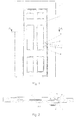
- FIGS. 1 and 2 a door 1 with a lock 2 is shown. Via the lock 2, the wing 3 of the door 1 can be fixed to the frame 4. A pusher 5 and a lock cylinder 6 are provided to operate the lock 2.
- the cross-section of the wing 3 is rectangular and lies in surfaces parallel alignment position to the frame 4 at this.
- the fold 8 of the wing 3 and the fold 9 of the frame 4 are in this case parallel to each other.
- the surface-parallel alignment position of the wing 3 and frame 4 - in accordance with Fig. 2 - Is referred to as a closed position and is independent of the intervention of a bolt 2 provided on the bolt 10 in a strike plate 11 on the frame. 4
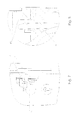
- FIGS. 3 and 4 can be seen by means of enlarged cutouts that the lock 2 is seated in a recess 12 of the wing 2.
- the lock 2 is closed by a lock plate 13, while extending perpendicular to the plane of the drawing walls 14 protrude from the castle floor.
- a latch 10 effective case 15 Through an opening in the lock plate 13 projects as a latch 10 effective case 15.
- another on the lock cylinder 6 operable latch on the lock 2 can be provided.
- the latch 15 is provided for the wing 3 in the closed position ( Fig. 2 ) each automatically set.
- the traps are usually spring loaded and always protrude - ie in the open position of the wing 3 - in front of the lock plate 13.
- a first magnet 16 is provided in the case 15.
- a second magnet 18 is provided in the strike plate 11, which is mounted along the fold 9 in a recess 17 of the frame 4.
- the magnet 16 and the magnet 18 are designed and assigned to one another in the closed position so that the latch 15 is displaced into a latch opening 19 of the striking plate 11.
- the magnet 16 is received by a case housing 20.
- the trap housing 20 is made of plastic, as this results in a cost-effective production and easy assembly (for example, by a snap-latch connection) with the magnet 16 on the one hand.
- the trap 15 is substantially cuboid, so that the longitudinal side surfaces are substantially perpendicular to the fold 8 and 9. Due to the obtuse angle of the locking surfaces of the case 15 a reliable locking is ensured.
- the pusher 5 is actuated, the case 15 is retracted in a conventional manner. This can also be done via lock cylinder 6, to which the lock 2 has a change control. When pressed pusher 5, the case 15 is completely withdrawn into the lock housing, as in the FIGS. 5 and 6 shown.
- the latch 15 is fixed in the non-surface-parallel position of the blade 3 in the lock housing or the lock 3 in that the first magnet 16 cooperates with the lock housing formed of a ferromagnetic material or a ferromagnetic component mounted therein or a magnetic component part.
- the lock housing is made of sheet metal. The setting of the trap 15 is necessary to ensure that the trap 15 is retracted when the wing 3 is to be closed again.
- the lock plate 13 is made of a non-ferromagnetic metal, preferably stainless steel, to avoid interference.
- the magnets 16, 18 interact again.
- the magnetic field of the first and second magnets 16, 18 in the closed position runs almost perpendicular to the lock face 13.
- the poles of the magnets 16, 18 are opposite each other in such a way that they attract each other.
- the Ausstellweite the case 15 5 is adjustable, so that too large or small spacing of the rabbets 8, 9 and thus the magnets 16, 18 can be counteracted.
- the magnet 18 is mounted in a receptacle 22 projecting on the rear side of the striking plate 11 and protrudes into a bore 23 of the frame 4.
- a bottom 24 of the closing plate 11 made of non-ferromagnetic material avoids an immediate meeting of the case 15 and the magnet 16 and the magnet 18, since the bottom 24 forms a separating gap.
- the magnet 16 is coated with plastic or covered by the case 20 so that it is not visible from the outside, to prevent tampering.
- the magnets 16, 18 are identical in terms of their dimensions.
- the magnet 18 is wrapped with a coil 25 which is connected via terminals to a door opening system, not shown here.
- a current which then flows through the coil 25.
- a magnetic field is built up, which is opposite to the magnet 15, so that acts on the latch 15, a restoring force, which forces the case 15 out of the latch opening 19, so that the case 15 in the FIGS. 5 and 6 position shown assumes.
- the voltage applied by the door opening system, which is applied to the coil 25, corresponds to that of a conventional door opener. If there is no voltage on the coil 25, the magnet 18 is effective as described above and moves the latch 15 in the latch opening 19 when the magnets 16, 18 facing each other.
- the strike plate is made of a non-ferromagnetic material. It also contributes to the fact that the lock forend as already mentioned above - consists of a non-ferromagnetic metal - preferably stainless steel.
- the above-described embodiment of the lock 2 has many advantages.
- the spring normally to be provided for displacing the latch 15 can be dispensed with. Because the trap 15 in the fixed non-surface-parallel position of the wing in the lock 2, the closed position can be achieved almost noiseless, since the case 15 does not coincide with the frame 4 or the closing bleach 11 during immersion of the wing 3.
- the trap 15 does not protrude, moreover, has the advantage that the trap does not protrude in front of the fold in the open position.
- the latter is advantageous, especially in the case of flush-fitting doors which do not cover the frame.
- rebated doors the wing 3 strikes the frame 4 and covers it with a rollover, which protrudes from the fold 8.
- the arrangement with the coil 25 also allows an arrangement of a door opener, which manages without moving parts.
- case 15 is adjustable relative to the fold 8. This takes place, for example via an adjusting device, as in the DE 10321354 A1 to which reference is made in this regard.
Landscapes
- Physics & Mathematics (AREA)
- Electromagnetism (AREA)
- Engineering & Computer Science (AREA)
- Mechanical Engineering (AREA)
- Lock And Its Accessories (AREA)
Abstract
Description
- Die Erfindung betrifft ein Schloss nach dem Oberbegriff des Anspruchs 1.
- Ein solches Schloss ist bereits aus der noch nicht veröffentlichten
DE 202008003477 U1 bekannt. Bei dem hieraus bekannten Schloss handelt es sich um ein Schloss mit einer Falle. Die Falle ist als selbsttätig durch Magnetkraft in Schließstellung des Flügels vortretenden Riegel ausgestaltet, dem am Rahmen ein Schließblech zugeordnet ist. Dabei greift die Falle in Verriegelungsstellung in eine Riegelöffnung eines Schließblechs ein, wobei die Falle aus einem Schlossgehäuse vortritt. Dazu ist die Falle mit einem ersten Magneten versehen und in dem Schließblech ist ein zweiter Magnet angebracht, so dass der erste und der zweite Magnet in Schließstellung des Flügels die Falle in das Schließblech verlagert. In nichtflächenparalleler Lage des Flügels wird die Falle in dem Schloss dadurch festgelegt, dass der erste Magnet mit dem Schlossgehäuse oder einem darin gelagerten magnetischen Metallteil zusammenwirkt. - Um ein Schloss von Ferne öffnen zu können, wird üblicherweise ein elektrischer Türöffner vorgesehen. Dieser weist eine schwenkbar gelagerte und über einen Elektromagnet schwenkbare Sperrklinke auf, welche in einer Fallenöffnung eines rahmenseitigen Schließblechs einsitzt. Bei aktiviertem Elektromagnet wird die Sperrklinke so verschwenkt, dass die Falle aus der Fallenöffnung austreten kann.
- Aus der
DE 29804032 U1 ist eine Ausgestaltung bekannt, bei der anstelle der schwenkbaren Sperrklinke ein beweglicher Bolzen vorgesehen ist, der mittels elektrischer Energie so bewegt wird, dass die Falle aus der Fallenöffnung gedrängt wird. - Nachteilig bei den bekannten Ausgestaltungen ist es, dass die bewegten Teile bei Einsatz des erstgenannten Schlosses nur aus nicht ferritischen Werkstoffen bestehen dürfen, da ansonsten die Falle an der Sperrklinke bzw. dem Bolzen hängenbleibt. Zudem ist die Beweglichkeit der Sperrklinke oder des Bolzens insbesondere nach einem gewissen Zeitablauf nicht mehr sicher gegeben.
- Aufgabe der Erfindung ist es daher ein Schloss anzugeben, welches neben einer sicheren Schließfunktion auch eine zuverlässige Türöffnerfunktion bereitstellt.
- Zur Lösung dieser Aufgabe ist vorgesehen, dass der Türöffner, aus einer ein elektrisches Feld erzeugenden Spule besteht, welches die Falle aus dem Schließblech drängt. Dadurch wird die Falle berührungslos mittels des elektrischen Signals aus dem Schließblech gedrängt. Dadurch ist eine äußerst einfache, kostengünstige und zugleich wirkungsvolle Ausgestaltung getroffen, die vollständig auf rahmenseitig bewegte Funktionsteile verzichtet.
- Um die bestehenden Türöffnungsanlagen weiterverwenden zu können, ist vorgesehen, dass die Spannung, welche an der Spule angelegt wird, der eines üblichen Türöffners entspricht.
- Besonders vorteilhaft ist es, wenn die Spule den Magnet in dem Schließblech umgibt. Dadurch entsteht ein dem Magnetfeld der Falle gegenüberstehendes Magnetfeld und es wird nur ein geringer Bauraum beansprucht.
- Weitere vorteilhafte Ausgestaltungen ergeben sich aus den Zeichnungen. Es zeigt:
- Fig. 1
- eine stumpf einschlagende Tür mit einem Schloss in einer Übersichtsdarstellung,
- Fig. 2
- eine Tür in einer Ansicht von oben,
- Fig. 3
- eine vergrößerte Darstellung des Schlosses mit einem Teilausschnitt der Falle und des Schließblechs mit einer in Verriegelungsstellung befindlichen Falle,
- Fig. 4
- einen vergrößerten Ausschnitt IV in der
Fig. 3 , - Fig. 5
- das Schloss nach
Fig. 3 mit betätigtem Drücker und - Fig. 6
- einen vergrößerten Ausschnitt VI in der
Fig. 5 . - In den
Fign. 1 und 2 ist eine Tür 1 mit einem Schloss 2 dargestellt. Über das Schloss 2 lässt sich der Flügel 3 der Tür 1 an dem Rahmen 4 festlegen. Ein Drücker 5 und ein Schließzylinder 6 sind vorgesehen, um das Schloss 2 zu bedienen. Ausweislich derFig. 2 ist der Querschnitt des Flügels 3 rechteckig und liegt in flächen paralleler Ausrichtlage zum Rahmen 4 an diesem an. Der Falz 8 des Flügels 3 und der Falz 9 des Rahmens 4 liegen sich hierbei parallel gegenüber. Die flächenparallele Ausrichtlage von Flügel 3 und Rahmen 4 - entsprechend derFig. 2 - wird als Schließstellung bezeichnet und ist unabhängig vom Eingriff eines am Schloss 2 vorgesehenen Riegels 10 in einem Schließblech 11 am Rahmen 4. - In den
Fign. 3 und 4 ist anhand vergrößerter Ausschnitte erkennbar, dass das Schloss 2 in einer Ausnehmung 12 des Flügels 2 einsitzt. Ein hier nicht sichtbarer Schlossboden und ein nicht dargestellter Schlossdeckel, die beide parallel zur Zeichnungsebene verlaufen, bilden ein Schlossgehäuse. Entlang des Falzes 8 wird das Schloss 2 durch einen Schlossstulp 13 verschlossen, während senkrecht zur Zeichnungsebene verlaufende Wände 14 von dem Schlossboden abstehen. - Durch eine Öffnung in dem Schlossstulp 13 ragt eine als Riegel 10 wirksame Falle 15. Neben der Falle 15 kann ein weiterer über den Schließzylinder 6 betätigbarer Riegel an dem Schloss 2 vorgesehen werden. Im Gegensatz zu dem gegebenenfalls vorgesehenen weiteren Riegel ist die Falle 15 dafür vorgesehen, den Flügel 3 in der Schließstellung (
Fig. 2 ) jeweils selbsttätig festzulegen. Dazu sind die Fallen üblicherweise federbelastet und ragen stets - also auch in Öffnungsstellung des Flügels 3 - vor den Schlossstulp 13 vor. - Bei dem dargestellten Schloss 2 ist in der Falle 15 ein erster Magnet 16 vorgesehen. In dem Schließblech 11, welches entlang dem Falz 9 in einer Ausnehmung 17 des Rahmens 4 angebracht ist, ist ein zweiter Magnet 18 vorgesehen. Der Magnet 16 und der Magnet 18 sind so ausgelegt und einander in der Schließstellung so zugeordnet, dass die Falle 15 in eine Riegelöffnung 19 des Schließblechs 11 verlagert wird.
- Dabei wird der Magnet 16 von einem Fallengehäuse 20 aufgenommen. Das Fallengehäuse 20 besteht aus Kunststoff, da sich dadurch zum einen eine kostengünstige Herstellung und einfache Montage (z.B. durch eine Rast-Schnapp-Verbindung) mit dem Magneten 16 ergibt. Zum anderen ist dadurch, dass der Magnet 16 in dem Fallengehäuse 20 aus nichtmagnetisierbaren Material aufgenommen ist, eine ggf. auftretende Wechselwirkungen mit dem Schließblech 11 ausgeschlossen, da der Magnet 16 nicht direkt mit ferromagnetischen Komponenten in Verbindung tritt, die eine Beeinflussung des Magnetfeldes mit sich bringen würden.
- Die Falle 15 ist im Wesentlichen quaderförmig, so dass die Längsseitenflächen im Wesentlichen senkrecht zu dem Falz 8 und 9 verlaufen. Durch den stumpfen Winkel der Riegelflächen der Falle 15 ist eine zuverlässige Verriegelung gewährleistet.
- Wird ausgehend von der Schließlage nach
Fign. 1 bis 4 der Drücker 5 betätigt, so wird die Falle 15 in an sich bekannter Weise zurückgezogen. Dies kann auch über Schließzylinder 6 erfolgen, wozu das Schloss 2 eine Wechselsteuerung aufweist. Bei betätigtem Drücker 5 wird die Falle 15 vollständig in das Schlossgehäuse zurückgezogen, wie in denFign. 5 und 6 dargestellt. - Wird der Flügel 3 nun verschwenkt, dann beeinflussen sich die Magnete 16, 17 nicht mehr gegenseitig. Dabei wird die Falle 15 in der nichtflächenparallelen Lage des Flügels 3 in dem Schlossgehäuse bzw. dem Schloss 3 dadurch festgelegt, dass der erste Magnet 16 mit dem aus einem ferromagnetischen Material gebildeten Schlossgehäuse oder einem darin gelagerten ferromagnetischen Bauteil oder einem magnetischen Bauteilteil zusammenwirkt. Die einfachste Ausgestaltung sieht dabei vor, dass das Schlossgehäuse aus Blech hergestellt wird. Das Festlegen der Falle 15 ist notwendig, um sicherzustellen, dass die Falle 15 zurückgezogen ist, wenn der Flügel 3 erneut geschlossen werden soll. Dem entgegen besteht der Schlossstulp 13 aus einem nicht-ferromagnetischen Metall vorzugsweise Edelstahl, um Beeinflussungen zu vermeiden.
- Gelangt der Flügel 3 erneut in die Schließstellung, entsprechend
Fign. 1 oder 2 , geraten die Magnete 16, 18 erneut in Wechselwirkung. Um diese Wechselwirkung sicherzustellen und ein vorzeitiges Herausziehen der Falle aus dem Schlossgehäuse zu vermeiden, ist vorgesehen, dass das Magnetfeld des ersten und des zweiten Magneten 16, 18 in der Schließstellung nahezu senkrecht zu dem Schlossstulp 13 verläuft. Selbstredend liegen sich die Pole der Magnete 16, 18 so gegenüber, dass sich diese anziehen. Um die Wechselwirkung der Magnete 16, 18 sicherzustellen, kann noch vorgesehen sein, dass die Ausstellweite der Falle 15 5 justierbar ist, so dass einem zu großen oder kleinen Abstand der Fälze 8, 9 und damit auch der Magnete 16, 18 entgegengewirkt werden kann. - Ausweislich der
Fig. 6 ist der Magnet 18 in einer rückseitig an dem Schließblech 11 vorragenden Aufnahme 22 angebracht und ragt in eine Bohrung 23 des Rahmens 4 vor. Ein Boden 24 des Schließblechs 11 aus nicht ferromagnetischem Material vermeidet ein unmittelbares Aufeinandertreffen der Falle 15 bzw. des Magneten 16 und des Magneten 18, da der Boden 24 einen Trennspalt bildet. Bei einem Anliegen der Magnete 16, 18 könnte es zu einem Verkleben dieser miteinander kommen. Zusätzlich dazu kann noch vorgesehen werden, dass der Magnet 16 mit Kunststoff umhüllt ist oder aber von dem Fallengehäuse 20 so abgedeckt ist, dass er von außen nicht sichtbar ist, um Manipulationen vorzubeugen. Um die Stückzahl der Magnete 16, 18 zu erhöhen und dadurch die Kosten zu reduzieren, kann noch vorgesehen werden, dass die Magnete 16, 18 hinsichtlich ihrer Abmessungen identisch sind. - In dem Ausführungsbeispiel nach
Fig. 3 und 4 ist der Magnet 18 mit einer Spule 25 umwickelt, welche über Klemmen an eine hier nicht dargestellte Türöffnungsanlage angeschlossen ist. Über die Türöffnungsanlage lässt sich in bekannter Art und Weise ein Strom auslösen, welcher dann die Spule 25 durchfließt. Dadurch wird ein Magnetfeld aufgebaut, welches dem Magnet 15 entgegengerichtet ist, so dass auf die Falle 15 eine rückstellende Kraft wirkt, welche die Falle 15 aus der Riegelöffnung 19 herausdrängt, so dass die Falle 15 die in denFign. 5 und 6 dargestellte Lage einnimmt. Vorzugsweise entspricht die von der Türöffnungsanlage ausgelöste Spannung, welche an der Spule 25 angelegt wird, der eines üblichen Türöffners. Liegt keine Spannung an der Spule 25 an, ist der Magnet 18 wie vorstehend beschrieben wirksam und verlagert die Falle 15 in die Riegelöffnung 19, wenn sich die Magnete 16, 18 gegenüberstehen. - Vorzugsweise ist - um Störungen zu vermeiden - auch vorgesehen, dass das Schließblech aus einem nicht-ferromagnetischen Werkstoff hergestellt ist. Dazu trägt auch bei, dass der Schlossstulp wie vorstehend bereits erwähnt - aus einem nicht-ferromagnetischen Metall - vorzugsweise Edelstahl - besteht.
- Die vorstehend beschriebene Ausgestaltung des Schlosses 2 hat viele Vorteile. Durch den in dem Schließblech 11 angebrachten zweiten Magneten 18 und dadurch, dass der erste und der zweite Magnet 16, 18 so zueinander angeordnet sind, dass in Schließstellung des Flügels die Falle in das Schließblech verlagert wird, kann eine selbsttätige Verriegelung entsprechend einer federbelasteten Falle erreicht werden. In dem Schloss 2 kann die üblicherweise vorzusehende Feder zur Verlagerung der Falle 15 jedoch entfallen. Dadurch, dass die Falle 15 in der nichtflächenparallelen Lage des Flügels in dem Schloss 2 festgelegt ist, kann die Schließstellung fast geräuschlos erreicht werden, da die Falle 15 nicht mit dem Rahmen 4 oder dem Schließbleich 11 beim Eintauchen des Flügels 3 zusammentrifft. Dass die Falle 15 nicht vorsteht, hat zudem den Vorteil, dass die Falle in der Öffnungsstellung nicht vor dem Falz vorragt. Letzteres ist, insbesondere bei stumpf einschlagenden Türen, die den Rahmen nicht überdecken, von Vorteil. Bei überfalzten Türen schlägt der Flügel 3 an dem Rahmen 4 an und überdeckt diesen mit einem Überschlag, der von dem Falz 8 absteht. Dadurch sind vorstehende Fallen für solche Türen kein Problem. Die Anordnung mit der Spule 25 erlaubt zudem eine Anordnung eines Türöffners, welcher ohne bewegliche Teile auskommt.
- Abschließend soll noch erwähnt werden, dass die Falle 15 relativ zum Falz 8 verstellbar ist. Dies erfolgt, z.B. über eine Verstelleinrichtung, wie in der
DE 10321354 A1 beschrieben, auf die diesbezüglich inhaltlich Bezug genommen wird. -
- 1
- Tür
- 2
- Schloss
- 3
- Flügel
- 4
- Rahmen
- 5
- Drücker
- 6
- Schließzylinder
- 8
- Falz
- 9
- Falz
- 10
- Riegel
- 11
- Schließblech
- 12
- Ausnehmung
- 13
- Schlossstulp
- 14
- Wand
- 15
- Falle
- 16
- Magnet
- 17
- Ausnehmung
- 18
- Magnet
- 19
- Riegelöffnung
- 20
- Fallengehäuse
- 22
- Aufnahme
- 23
- Bohrung
- 24
- Boden
- 25
- Spule
Claims (3)
- Schloss (2) für eine Tür oder ein Fenster, mit einem zumindest schwenkbar an einem Rahmen (4) gelagerten Flügel (3), mit einem selbsttätig durch Magnetkraft in Schließstellung vortretenden Riegel (10), dem am Rahmen (4) ein Schließblech (11) zugeordnet ist, wobei der Riegel (10) eine in Verriegelungsstellung in eine Riegelöffnung (19) des Schließblechs (11) eingreifende und aus einem Schlossgehäuse vortretende Falle (15) mit einem ersten Magneten (16) ist, und wobei in dem Schließblech (11) ein zweiter Magnet (18) angebracht ist, wobei der erste und der zweite Magnet (16, 18) so zueinander angeordnet sind, dass in Schließstellung des Flügels (3) die Falle (15) in das Schließblech (11) verlagert wird und dass die Falle (15) in der nichtflächenparallelen Lage des Flügels (3) in dem Schloss (2) dadurch festgelegt ist, dass der erste Magnet (16) mit dem Schlossgehäuse oder einem darin gelagerten magnetischen Metallteil zusammenwirkt, gekennzeichnet durch einen Türöffner, der aus einer ein elektrisches Feld erzeugenden Spule (25) besteht, welches die Falle (15) aus dem Schließblech (11) drängt.
- Schloss (2) nach Anspruch 1, dadurch gekennzeichnet, dass die Spannung, welche an der Spule (25) angelegt wird, der eines üblichen Türöffners entspricht.
- Schloss (2) nach Anspruch 1 oder 2, dadurch gekennzeichnet, dass die Spule (25) den Magnet (18) in dem Schließblech (11) umgibt.
Priority Applications (1)
| Application Number | Priority Date | Filing Date | Title |
|---|---|---|---|
| PL10164447T PL2267252T3 (pl) | 2009-06-22 | 2010-05-31 | Układ zamka |
Applications Claiming Priority (1)
| Application Number | Priority Date | Filing Date | Title |
|---|---|---|---|
| DE202009008644U DE202009008644U1 (de) | 2009-06-22 | 2009-06-22 | Schloss |
Publications (3)
| Publication Number | Publication Date |
|---|---|
| EP2267252A2 true EP2267252A2 (de) | 2010-12-29 |
| EP2267252A3 EP2267252A3 (de) | 2013-08-28 |
| EP2267252B1 EP2267252B1 (de) | 2014-11-26 |
Family
ID=42937242
Family Applications (1)
| Application Number | Title | Priority Date | Filing Date |
|---|---|---|---|
| EP10164447.4A Active EP2267252B1 (de) | 2009-06-22 | 2010-05-31 | Schlossanordnung |
Country Status (3)
| Country | Link |
|---|---|
| EP (1) | EP2267252B1 (de) |
| DE (1) | DE202009008644U1 (de) |
| PL (1) | PL2267252T3 (de) |
Cited By (3)
| Publication number | Priority date | Publication date | Assignee | Title |
|---|---|---|---|---|
| CN105421898A (zh) * | 2015-12-24 | 2016-03-23 | 佛山市汇泰龙智能科技有限公司 | 一种磁力静音锁体 |
| CN106193805A (zh) * | 2016-08-29 | 2016-12-07 | 温州科力智能五金有限公司 | 一种静音门锁 |
| BE1026669B1 (nl) * | 2018-10-03 | 2020-05-05 | Molenzicht Bvba | Verbeterd automatisch magnetisch deuropeningssysteem |
Families Citing this family (4)
| Publication number | Priority date | Publication date | Assignee | Title |
|---|---|---|---|---|
| DE102011107472B4 (de) * | 2011-07-08 | 2014-02-20 | Assa Abloy Sicherheitstechnik Gmbh | Türöffnereinrichtung mit Permanentmagnet |
| DE202013001328U1 (de) * | 2013-02-13 | 2013-03-15 | Kfv Karl Fliether Gmbh & Co. Kg | Kontaktanordnung |
| CN104863431B (zh) * | 2015-05-22 | 2017-03-01 | 浙江宏泰电子设备有限公司 | 电动开门器 |
| TWI717254B (zh) * | 2020-04-10 | 2021-01-21 | 簡文豐 | 磁動式閂鎖裝置 |
Citations (3)
| Publication number | Priority date | Publication date | Assignee | Title |
|---|---|---|---|---|
| DE29804032U1 (de) | 1998-03-07 | 1998-05-14 | Heger, Karl, 39326 Zielitz | Elektrischer Türöffner mit Bolzen |
| DE10321354A1 (de) | 2003-05-13 | 2004-12-02 | Karl Fliether Gmbh & Co. Kg | Schloss mit längeneinstellbarer Falle |
| DE202008003477U1 (de) | 2008-03-11 | 2009-07-30 | Kfv Karl Fliether Gmbh & Co. Kg | Schloss |
Family Cites Families (7)
| Publication number | Priority date | Publication date | Assignee | Title |
|---|---|---|---|---|
| GB265396A (en) * | 1926-02-25 | 1927-02-10 | Victor Booth | Improvements in or relating to locking devices operated electrically from a distance |
| FR762352A (fr) * | 1933-10-13 | 1934-04-10 | Serrure électrique | |
| NL8204459A (nl) * | 1982-11-17 | 1984-06-18 | Albert Van Dillen | Slot. |
| DE4337426C2 (de) * | 1993-11-03 | 2003-04-30 | Bosch Gmbh Robert | Vorrichtung zum Verhindern des Zugangs zu einem mit einer Tür verschließbaren geschützten Sicherheitsbereich |
| GB2286627B (en) * | 1993-12-28 | 1997-04-16 | Total Prod Sales Ltd | Door latch lock |
| GB0508109D0 (en) * | 2005-04-22 | 2005-06-01 | Entryphone The Co Ltd | A lock assembly |
| ITMI20061352A1 (it) * | 2006-07-12 | 2008-01-13 | Bonaiti Serrature Spa | Serratura ad azionamento magnetico perfezionato |
-
2009
- 2009-06-22 DE DE202009008644U patent/DE202009008644U1/de not_active Expired - Lifetime
-
2010
- 2010-05-31 EP EP10164447.4A patent/EP2267252B1/de active Active
- 2010-05-31 PL PL10164447T patent/PL2267252T3/pl unknown
Patent Citations (3)
| Publication number | Priority date | Publication date | Assignee | Title |
|---|---|---|---|---|
| DE29804032U1 (de) | 1998-03-07 | 1998-05-14 | Heger, Karl, 39326 Zielitz | Elektrischer Türöffner mit Bolzen |
| DE10321354A1 (de) | 2003-05-13 | 2004-12-02 | Karl Fliether Gmbh & Co. Kg | Schloss mit längeneinstellbarer Falle |
| DE202008003477U1 (de) | 2008-03-11 | 2009-07-30 | Kfv Karl Fliether Gmbh & Co. Kg | Schloss |
Cited By (3)
| Publication number | Priority date | Publication date | Assignee | Title |
|---|---|---|---|---|
| CN105421898A (zh) * | 2015-12-24 | 2016-03-23 | 佛山市汇泰龙智能科技有限公司 | 一种磁力静音锁体 |
| CN106193805A (zh) * | 2016-08-29 | 2016-12-07 | 温州科力智能五金有限公司 | 一种静音门锁 |
| BE1026669B1 (nl) * | 2018-10-03 | 2020-05-05 | Molenzicht Bvba | Verbeterd automatisch magnetisch deuropeningssysteem |
Also Published As
| Publication number | Publication date |
|---|---|
| PL2267252T3 (pl) | 2015-04-30 |
| EP2267252B1 (de) | 2014-11-26 |
| DE202009008644U1 (de) | 2010-11-04 |
| EP2267252A3 (de) | 2013-08-28 |
Similar Documents
| Publication | Publication Date | Title |
|---|---|---|
| EP2267252B1 (de) | Schlossanordnung | |
| DE19728273C1 (de) | Verriegelungseinrichtung für Möbel | |
| DE19501420C1 (de) | Verriegelung | |
| EP1447500B1 (de) | Sicherheitszuhaltung | |
| EP3266963A1 (de) | Verriegelungssystem | |
| EP2255051B1 (de) | Schloss | |
| DE102008011551A1 (de) | Selbstverriegelnde Zusatzverriegelung | |
| DE102015117415A1 (de) | Türöffner | |
| EP0657606A1 (de) | Durch einen Schlüssel und/oder durch einen Drücker betätigbares Antipanik-Hotelschloss | |
| EP2354402B1 (de) | Verriegelung für Flügelanlagen | |
| DE19730552C1 (de) | Einrichtung zum Entriegeln eines mechanisch selbstverriegelnden Mehrfachschlosses | |
| EP1056915B1 (de) | Türschloss | |
| DE4337426A1 (de) | Verfahren und Vorrichtung zum Verhindern des Zugangs zu einem mit einer Tür verschließbaren geschützten Sicherheitsbereich | |
| DE202011001546U1 (de) | Sicherungsvorrichtung für die Absicherung eines beweglich gelagerten Türflügels | |
| DE102011118892A1 (de) | Verriegelungsanordnung | |
| EP2543797B1 (de) | Türöffnereinrichtung mit Permanentmagnet | |
| DE19943497A1 (de) | Abdeckvorrichtung für einen in einer Griffplatte o. dgl. eines Türgriffs angeordneten Schliesszylinders eines Kraftfahrzeugtürverschlusses | |
| DE2554174A1 (de) | Elektrischer tueroeffner | |
| DE202011105510U1 (de) | Türöffner mit Sperr-Riegel | |
| DE102012009067B3 (de) | Aufschlagsicherer Türöffner | |
| DE202015005011U1 (de) | Glanzglastür | |
| DE102013012203B4 (de) | Elektrischer Türöffner sowie ein Passivflügelschloss mit einem solchen Türöffner | |
| DE10051234C2 (de) | Verriegelbare geteilte Schiebetür mit zwei Türblättern | |
| DE202010006314U1 (de) | Einsteckschloss | |
| DE102013105487A1 (de) | Verriegelungseinheit für eine Schließanlage |
Legal Events
| Date | Code | Title | Description |
|---|---|---|---|
| PUAI | Public reference made under article 153(3) epc to a published international application that has entered the european phase |
Free format text: ORIGINAL CODE: 0009012 |
|
| AK | Designated contracting states |
Kind code of ref document: A2 Designated state(s): AL AT BE BG CH CY CZ DE DK EE ES FI FR GB GR HR HU IE IS IT LI LT LU LV MC MK MT NL NO PL PT RO SE SI SK SM TR |
|
| AX | Request for extension of the european patent |
Extension state: BA ME RS |
|
| PUAL | Search report despatched |
Free format text: ORIGINAL CODE: 0009013 |
|
| AK | Designated contracting states |
Kind code of ref document: A3 Designated state(s): AL AT BE BG CH CY CZ DE DK EE ES FI FR GB GR HR HU IE IS IT LI LT LU LV MC MK MT NL NO PL PT RO SE SI SK SM TR |
|
| AX | Request for extension of the european patent |
Extension state: BA ME RS |
|
| RIC1 | Information provided on ipc code assigned before grant |
Ipc: E05B 63/06 20060101ALN20130725BHEP Ipc: E05B 47/00 20060101AFI20130725BHEP Ipc: E05B 47/04 20060101ALI20130725BHEP |
|
| 17P | Request for examination filed |
Effective date: 20130925 |
|
| GRAP | Despatch of communication of intention to grant a patent |
Free format text: ORIGINAL CODE: EPIDOSNIGR1 |
|
| GRAJ | Information related to disapproval of communication of intention to grant by the applicant or resumption of examination proceedings by the epo deleted |
Free format text: ORIGINAL CODE: EPIDOSDIGR1 |
|
| RIC1 | Information provided on ipc code assigned before grant |
Ipc: E05B 15/10 20060101ALN20140610BHEP Ipc: E05B 63/06 20060101ALN20140610BHEP Ipc: E05B 15/16 20060101ALN20140610BHEP Ipc: E05B 47/00 20060101AFI20140610BHEP Ipc: E05B 47/04 20060101ALI20140610BHEP |
|
| INTG | Intention to grant announced |
Effective date: 20140707 |
|
| RIC1 | Information provided on ipc code assigned before grant |
Ipc: E05B 47/00 20060101AFI20140702BHEP Ipc: E05B 47/04 20060101ALI20140702BHEP Ipc: E05B 15/16 20060101ALN20140702BHEP Ipc: E05B 15/10 20060101ALN20140702BHEP Ipc: E05B 63/06 20060101ALN20140702BHEP |
|
| INTC | Intention to grant announced (deleted) | ||
| RIC1 | Information provided on ipc code assigned before grant |
Ipc: E05B 15/10 20060101ALN20140708BHEP Ipc: E05B 63/06 20060101ALN20140708BHEP Ipc: E05B 47/00 20060101AFI20140708BHEP Ipc: E05B 47/04 20060101ALI20140708BHEP Ipc: E05B 15/16 20060101ALN20140708BHEP |
|
| GRAP | Despatch of communication of intention to grant a patent |
Free format text: ORIGINAL CODE: EPIDOSNIGR1 |
|
| INTG | Intention to grant announced |
Effective date: 20140821 |
|
| GRAS | Grant fee paid |
Free format text: ORIGINAL CODE: EPIDOSNIGR3 |
|
| GRAA | (expected) grant |
Free format text: ORIGINAL CODE: 0009210 |
|
| AK | Designated contracting states |
Kind code of ref document: B1 Designated state(s): AL AT BE BG CH CY CZ DE DK EE ES FI FR GB GR HR HU IE IS IT LI LT LU LV MC MK MT NL NO PL PT RO SE SI SK SM TR |
|
| REG | Reference to a national code |
Ref country code: GB Ref legal event code: FG4D Free format text: NOT ENGLISH |
|
| REG | Reference to a national code |
Ref country code: CH Ref legal event code: EP |
|
| REG | Reference to a national code |
Ref country code: AT Ref legal event code: REF Ref document number: 698328 Country of ref document: AT Kind code of ref document: T Effective date: 20141215 |
|
| REG | Reference to a national code |
Ref country code: IE Ref legal event code: FG4D Free format text: LANGUAGE OF EP DOCUMENT: GERMAN |
|
| REG | Reference to a national code |
Ref country code: DE Ref legal event code: R096 Ref document number: 502010008331 Country of ref document: DE Effective date: 20141231 |
|
| REG | Reference to a national code |
Ref country code: NL Ref legal event code: T3 |
|
| REG | Reference to a national code |
Ref country code: LT Ref legal event code: MG4D |
|
| PG25 | Lapsed in a contracting state [announced via postgrant information from national office to epo] |
Ref country code: LT Free format text: LAPSE BECAUSE OF FAILURE TO SUBMIT A TRANSLATION OF THE DESCRIPTION OR TO PAY THE FEE WITHIN THE PRESCRIBED TIME-LIMIT Effective date: 20141126 Ref country code: NO Free format text: LAPSE BECAUSE OF FAILURE TO SUBMIT A TRANSLATION OF THE DESCRIPTION OR TO PAY THE FEE WITHIN THE PRESCRIBED TIME-LIMIT Effective date: 20150226 Ref country code: ES Free format text: LAPSE BECAUSE OF FAILURE TO SUBMIT A TRANSLATION OF THE DESCRIPTION OR TO PAY THE FEE WITHIN THE PRESCRIBED TIME-LIMIT Effective date: 20141126 Ref country code: PT Free format text: LAPSE BECAUSE OF FAILURE TO SUBMIT A TRANSLATION OF THE DESCRIPTION OR TO PAY THE FEE WITHIN THE PRESCRIBED TIME-LIMIT Effective date: 20150326 Ref country code: IS Free format text: LAPSE BECAUSE OF FAILURE TO SUBMIT A TRANSLATION OF THE DESCRIPTION OR TO PAY THE FEE WITHIN THE PRESCRIBED TIME-LIMIT Effective date: 20150326 Ref country code: FI Free format text: LAPSE BECAUSE OF FAILURE TO SUBMIT A TRANSLATION OF THE DESCRIPTION OR TO PAY THE FEE WITHIN THE PRESCRIBED TIME-LIMIT Effective date: 20141126 |
|
| REG | Reference to a national code |
Ref country code: PL Ref legal event code: T3 |
|
| PG25 | Lapsed in a contracting state [announced via postgrant information from national office to epo] |
Ref country code: HR Free format text: LAPSE BECAUSE OF FAILURE TO SUBMIT A TRANSLATION OF THE DESCRIPTION OR TO PAY THE FEE WITHIN THE PRESCRIBED TIME-LIMIT Effective date: 20141126 Ref country code: LV Free format text: LAPSE BECAUSE OF FAILURE TO SUBMIT A TRANSLATION OF THE DESCRIPTION OR TO PAY THE FEE WITHIN THE PRESCRIBED TIME-LIMIT Effective date: 20141126 Ref country code: CY Free format text: LAPSE BECAUSE OF FAILURE TO SUBMIT A TRANSLATION OF THE DESCRIPTION OR TO PAY THE FEE WITHIN THE PRESCRIBED TIME-LIMIT Effective date: 20141126 Ref country code: SE Free format text: LAPSE BECAUSE OF FAILURE TO SUBMIT A TRANSLATION OF THE DESCRIPTION OR TO PAY THE FEE WITHIN THE PRESCRIBED TIME-LIMIT Effective date: 20141126 Ref country code: GR Free format text: LAPSE BECAUSE OF FAILURE TO SUBMIT A TRANSLATION OF THE DESCRIPTION OR TO PAY THE FEE WITHIN THE PRESCRIBED TIME-LIMIT Effective date: 20150227 |
|
| PG25 | Lapsed in a contracting state [announced via postgrant information from national office to epo] |
Ref country code: EE Free format text: LAPSE BECAUSE OF FAILURE TO SUBMIT A TRANSLATION OF THE DESCRIPTION OR TO PAY THE FEE WITHIN THE PRESCRIBED TIME-LIMIT Effective date: 20141126 Ref country code: SK Free format text: LAPSE BECAUSE OF FAILURE TO SUBMIT A TRANSLATION OF THE DESCRIPTION OR TO PAY THE FEE WITHIN THE PRESCRIBED TIME-LIMIT Effective date: 20141126 Ref country code: CZ Free format text: LAPSE BECAUSE OF FAILURE TO SUBMIT A TRANSLATION OF THE DESCRIPTION OR TO PAY THE FEE WITHIN THE PRESCRIBED TIME-LIMIT Effective date: 20141126 Ref country code: RO Free format text: LAPSE BECAUSE OF FAILURE TO SUBMIT A TRANSLATION OF THE DESCRIPTION OR TO PAY THE FEE WITHIN THE PRESCRIBED TIME-LIMIT Effective date: 20141126 Ref country code: DK Free format text: LAPSE BECAUSE OF FAILURE TO SUBMIT A TRANSLATION OF THE DESCRIPTION OR TO PAY THE FEE WITHIN THE PRESCRIBED TIME-LIMIT Effective date: 20141126 |
|
| REG | Reference to a national code |
Ref country code: DE Ref legal event code: R097 Ref document number: 502010008331 Country of ref document: DE |
|
| PLBE | No opposition filed within time limit |
Free format text: ORIGINAL CODE: 0009261 |
|
| STAA | Information on the status of an ep patent application or granted ep patent |
Free format text: STATUS: NO OPPOSITION FILED WITHIN TIME LIMIT |
|
| 26N | No opposition filed |
Effective date: 20150827 |
|
| PG25 | Lapsed in a contracting state [announced via postgrant information from national office to epo] |
Ref country code: LU Free format text: LAPSE BECAUSE OF FAILURE TO SUBMIT A TRANSLATION OF THE DESCRIPTION OR TO PAY THE FEE WITHIN THE PRESCRIBED TIME-LIMIT Effective date: 20150531 Ref country code: MC Free format text: LAPSE BECAUSE OF FAILURE TO SUBMIT A TRANSLATION OF THE DESCRIPTION OR TO PAY THE FEE WITHIN THE PRESCRIBED TIME-LIMIT Effective date: 20141126 |
|
| REG | Reference to a national code |
Ref country code: IE Ref legal event code: MM4A |
|
| PG25 | Lapsed in a contracting state [announced via postgrant information from national office to epo] |
Ref country code: SI Free format text: LAPSE BECAUSE OF FAILURE TO SUBMIT A TRANSLATION OF THE DESCRIPTION OR TO PAY THE FEE WITHIN THE PRESCRIBED TIME-LIMIT Effective date: 20141126 |
|
| PG25 | Lapsed in a contracting state [announced via postgrant information from national office to epo] |
Ref country code: IE Free format text: LAPSE BECAUSE OF NON-PAYMENT OF DUE FEES Effective date: 20150531 |
|
| REG | Reference to a national code |
Ref country code: FR Ref legal event code: PLFP Year of fee payment: 7 |
|
| PGFP | Annual fee paid to national office [announced via postgrant information from national office to epo] |
Ref country code: NL Payment date: 20160509 Year of fee payment: 7 |
|
| PGFP | Annual fee paid to national office [announced via postgrant information from national office to epo] |
Ref country code: GB Payment date: 20160512 Year of fee payment: 7 |
|
| PGFP | Annual fee paid to national office [announced via postgrant information from national office to epo] |
Ref country code: BE Payment date: 20160509 Year of fee payment: 7 Ref country code: IT Payment date: 20160531 Year of fee payment: 7 Ref country code: PL Payment date: 20160420 Year of fee payment: 7 |
|
| PG25 | Lapsed in a contracting state [announced via postgrant information from national office to epo] |
Ref country code: MT Free format text: LAPSE BECAUSE OF FAILURE TO SUBMIT A TRANSLATION OF THE DESCRIPTION OR TO PAY THE FEE WITHIN THE PRESCRIBED TIME-LIMIT Effective date: 20141126 |
|
| REG | Reference to a national code |
Ref country code: FR Ref legal event code: PLFP Year of fee payment: 8 |
|
| PG25 | Lapsed in a contracting state [announced via postgrant information from national office to epo] |
Ref country code: SM Free format text: LAPSE BECAUSE OF FAILURE TO SUBMIT A TRANSLATION OF THE DESCRIPTION OR TO PAY THE FEE WITHIN THE PRESCRIBED TIME-LIMIT Effective date: 20141126 Ref country code: BG Free format text: LAPSE BECAUSE OF FAILURE TO SUBMIT A TRANSLATION OF THE DESCRIPTION OR TO PAY THE FEE WITHIN THE PRESCRIBED TIME-LIMIT Effective date: 20141126 Ref country code: HU Free format text: LAPSE BECAUSE OF FAILURE TO SUBMIT A TRANSLATION OF THE DESCRIPTION OR TO PAY THE FEE WITHIN THE PRESCRIBED TIME-LIMIT; INVALID AB INITIO Effective date: 20100531 |
|
| PG25 | Lapsed in a contracting state [announced via postgrant information from national office to epo] |
Ref country code: TR Free format text: LAPSE BECAUSE OF FAILURE TO SUBMIT A TRANSLATION OF THE DESCRIPTION OR TO PAY THE FEE WITHIN THE PRESCRIBED TIME-LIMIT Effective date: 20141126 |
|
| REG | Reference to a national code |
Ref country code: NL Ref legal event code: MM Effective date: 20170601 |
|
| GBPC | Gb: european patent ceased through non-payment of renewal fee |
Effective date: 20170531 |
|
| PG25 | Lapsed in a contracting state [announced via postgrant information from national office to epo] |
Ref country code: NL Free format text: LAPSE BECAUSE OF NON-PAYMENT OF DUE FEES Effective date: 20170601 |
|
| REG | Reference to a national code |
Ref country code: BE Ref legal event code: MM Effective date: 20170531 |
|
| PG25 | Lapsed in a contracting state [announced via postgrant information from national office to epo] |
Ref country code: GB Free format text: LAPSE BECAUSE OF NON-PAYMENT OF DUE FEES Effective date: 20170531 |
|
| REG | Reference to a national code |
Ref country code: FR Ref legal event code: PLFP Year of fee payment: 9 |
|
| PG25 | Lapsed in a contracting state [announced via postgrant information from national office to epo] |
Ref country code: IT Free format text: LAPSE BECAUSE OF NON-PAYMENT OF DUE FEES Effective date: 20170531 |
|
| PG25 | Lapsed in a contracting state [announced via postgrant information from national office to epo] |
Ref country code: MK Free format text: LAPSE BECAUSE OF FAILURE TO SUBMIT A TRANSLATION OF THE DESCRIPTION OR TO PAY THE FEE WITHIN THE PRESCRIBED TIME-LIMIT Effective date: 20141126 |
|
| PG25 | Lapsed in a contracting state [announced via postgrant information from national office to epo] |
Ref country code: BE Free format text: LAPSE BECAUSE OF NON-PAYMENT OF DUE FEES Effective date: 20170531 |
|
| PG25 | Lapsed in a contracting state [announced via postgrant information from national office to epo] |
Ref country code: PL Free format text: LAPSE BECAUSE OF NON-PAYMENT OF DUE FEES Effective date: 20170531 Ref country code: AL Free format text: LAPSE BECAUSE OF FAILURE TO SUBMIT A TRANSLATION OF THE DESCRIPTION OR TO PAY THE FEE WITHIN THE PRESCRIBED TIME-LIMIT Effective date: 20141126 |
|
| PGFP | Annual fee paid to national office [announced via postgrant information from national office to epo] |
Ref country code: DE Payment date: 20250602 Year of fee payment: 16 |
|
| PGFP | Annual fee paid to national office [announced via postgrant information from national office to epo] |
Ref country code: FR Payment date: 20250520 Year of fee payment: 16 |
|
| PGFP | Annual fee paid to national office [announced via postgrant information from national office to epo] |
Ref country code: CH Payment date: 20250601 Year of fee payment: 16 |
|
| PGFP | Annual fee paid to national office [announced via postgrant information from national office to epo] |
Ref country code: AT Payment date: 20250526 Year of fee payment: 16 |