EP2267320B1 - Elément de fixation - Google Patents
Elément de fixation Download PDFInfo
- Publication number
- EP2267320B1 EP2267320B1 EP10006577A EP10006577A EP2267320B1 EP 2267320 B1 EP2267320 B1 EP 2267320B1 EP 10006577 A EP10006577 A EP 10006577A EP 10006577 A EP10006577 A EP 10006577A EP 2267320 B1 EP2267320 B1 EP 2267320B1
- Authority
- EP
- European Patent Office
- Prior art keywords
- fastening
- hook
- screw
- fastening element
- profile
- Prior art date
- Legal status (The legal status is an assumption and is not a legal conclusion. Google has not performed a legal analysis and makes no representation as to the accuracy of the status listed.)
- Active
Links
Images


Classifications
-
- F—MECHANICAL ENGINEERING; LIGHTING; HEATING; WEAPONS; BLASTING
- F16—ENGINEERING ELEMENTS AND UNITS; GENERAL MEASURES FOR PRODUCING AND MAINTAINING EFFECTIVE FUNCTIONING OF MACHINES OR INSTALLATIONS; THERMAL INSULATION IN GENERAL
- F16B—DEVICES FOR FASTENING OR SECURING CONSTRUCTIONAL ELEMENTS OR MACHINE PARTS TOGETHER, e.g. NAILS, BOLTS, CIRCLIPS, CLAMPS, CLIPS OR WEDGES; JOINTS OR JOINTING
- F16B37/00—Nuts or like thread-engaging members
- F16B37/04—Devices for fastening nuts to surfaces, e.g. sheets, plates
- F16B37/045—Devices for fastening nuts to surfaces, e.g. sheets, plates specially adapted for fastening in channels, e.g. sliding bolts, channel nuts
-
- F—MECHANICAL ENGINEERING; LIGHTING; HEATING; WEAPONS; BLASTING
- F24—HEATING; RANGES; VENTILATING
- F24S—SOLAR HEAT COLLECTORS; SOLAR HEAT SYSTEMS
- F24S20/00—Solar heat collectors specially adapted for particular uses or environments
- F24S20/60—Solar heat collectors integrated in fixed constructions, e.g. in buildings
- F24S20/67—Solar heat collectors integrated in fixed constructions, e.g. in buildings in the form of roof constructions
-
- F—MECHANICAL ENGINEERING; LIGHTING; HEATING; WEAPONS; BLASTING
- F24—HEATING; RANGES; VENTILATING
- F24S—SOLAR HEAT COLLECTORS; SOLAR HEAT SYSTEMS
- F24S25/00—Arrangement of stationary mountings or supports for solar heat collector modules
- F24S25/30—Arrangement of stationary mountings or supports for solar heat collector modules using elongate rigid mounting elements extending substantially along the supporting surface, e.g. for covering buildings with solar heat collectors
- F24S25/33—Arrangement of stationary mountings or supports for solar heat collector modules using elongate rigid mounting elements extending substantially along the supporting surface, e.g. for covering buildings with solar heat collectors forming substantially planar assemblies, e.g. of coplanar or stacked profiles
-
- F—MECHANICAL ENGINEERING; LIGHTING; HEATING; WEAPONS; BLASTING
- F24—HEATING; RANGES; VENTILATING
- F24S—SOLAR HEAT COLLECTORS; SOLAR HEAT SYSTEMS
- F24S25/00—Arrangement of stationary mountings or supports for solar heat collector modules
- F24S25/60—Fixation means, e.g. fasteners, specially adapted for supporting solar heat collector modules
- F24S25/61—Fixation means, e.g. fasteners, specially adapted for supporting solar heat collector modules for fixing to the ground or to building structures
- F24S25/613—Fixation means, e.g. fasteners, specially adapted for supporting solar heat collector modules for fixing to the ground or to building structures in the form of bent strips or assemblies of strips; Hook-like connectors; Connectors to be mounted between building-covering elements
-
- F—MECHANICAL ENGINEERING; LIGHTING; HEATING; WEAPONS; BLASTING
- F24—HEATING; RANGES; VENTILATING
- F24S—SOLAR HEAT COLLECTORS; SOLAR HEAT SYSTEMS
- F24S25/00—Arrangement of stationary mountings or supports for solar heat collector modules
- F24S25/60—Fixation means, e.g. fasteners, specially adapted for supporting solar heat collector modules
- F24S25/63—Fixation means, e.g. fasteners, specially adapted for supporting solar heat collector modules for fixing modules or their peripheral frames to supporting elements
- F24S25/634—Clamps; Clips
- F24S25/636—Clamps; Clips clamping by screw-threaded elements
-
- F—MECHANICAL ENGINEERING; LIGHTING; HEATING; WEAPONS; BLASTING
- F24—HEATING; RANGES; VENTILATING
- F24S—SOLAR HEAT COLLECTORS; SOLAR HEAT SYSTEMS
- F24S25/00—Arrangement of stationary mountings or supports for solar heat collector modules
- F24S25/60—Fixation means, e.g. fasteners, specially adapted for supporting solar heat collector modules
- F24S25/65—Fixation means, e.g. fasteners, specially adapted for supporting solar heat collector modules for coupling adjacent supporting elements, e.g. for connecting profiles together
-
- H—ELECTRICITY
- H02—GENERATION; CONVERSION OR DISTRIBUTION OF ELECTRIC POWER
- H02S—GENERATION OF ELECTRIC POWER BY CONVERSION OF INFRARED RADIATION, VISIBLE LIGHT OR ULTRAVIOLET LIGHT, e.g. USING PHOTOVOLTAIC [PV] MODULES
- H02S20/00—Supporting structures for PV modules
- H02S20/20—Supporting structures directly fixed to an immovable object
- H02S20/22—Supporting structures directly fixed to an immovable object specially adapted for buildings
- H02S20/23—Supporting structures directly fixed to an immovable object specially adapted for buildings specially adapted for roof structures
-
- F—MECHANICAL ENGINEERING; LIGHTING; HEATING; WEAPONS; BLASTING
- F24—HEATING; RANGES; VENTILATING
- F24S—SOLAR HEAT COLLECTORS; SOLAR HEAT SYSTEMS
- F24S25/00—Arrangement of stationary mountings or supports for solar heat collector modules
- F24S25/60—Fixation means, e.g. fasteners, specially adapted for supporting solar heat collector modules
- F24S2025/6002—Fixation means, e.g. fasteners, specially adapted for supporting solar heat collector modules by using hooks
-
- F—MECHANICAL ENGINEERING; LIGHTING; HEATING; WEAPONS; BLASTING
- F24—HEATING; RANGES; VENTILATING
- F24S—SOLAR HEAT COLLECTORS; SOLAR HEAT SYSTEMS
- F24S25/00—Arrangement of stationary mountings or supports for solar heat collector modules
- F24S2025/80—Special profiles
- F24S2025/801—Special profiles having hollow parts with closed cross-section
-
- F—MECHANICAL ENGINEERING; LIGHTING; HEATING; WEAPONS; BLASTING
- F24—HEATING; RANGES; VENTILATING
- F24S—SOLAR HEAT COLLECTORS; SOLAR HEAT SYSTEMS
- F24S25/00—Arrangement of stationary mountings or supports for solar heat collector modules
- F24S2025/80—Special profiles
- F24S2025/807—Special profiles having undercut grooves
-
- F—MECHANICAL ENGINEERING; LIGHTING; HEATING; WEAPONS; BLASTING
- F24—HEATING; RANGES; VENTILATING
- F24S—SOLAR HEAT COLLECTORS; SOLAR HEAT SYSTEMS
- F24S25/00—Arrangement of stationary mountings or supports for solar heat collector modules
- F24S25/10—Arrangement of stationary mountings or supports for solar heat collector modules extending in directions away from a supporting surface
- F24S25/12—Arrangement of stationary mountings or supports for solar heat collector modules extending in directions away from a supporting surface using posts in combination with upper profiles
-
- Y—GENERAL TAGGING OF NEW TECHNOLOGICAL DEVELOPMENTS; GENERAL TAGGING OF CROSS-SECTIONAL TECHNOLOGIES SPANNING OVER SEVERAL SECTIONS OF THE IPC; TECHNICAL SUBJECTS COVERED BY FORMER USPC CROSS-REFERENCE ART COLLECTIONS [XRACs] AND DIGESTS
- Y02—TECHNOLOGIES OR APPLICATIONS FOR MITIGATION OR ADAPTATION AGAINST CLIMATE CHANGE
- Y02B—CLIMATE CHANGE MITIGATION TECHNOLOGIES RELATED TO BUILDINGS, e.g. HOUSING, HOUSE APPLIANCES OR RELATED END-USER APPLICATIONS
- Y02B10/00—Integration of renewable energy sources in buildings
- Y02B10/10—Photovoltaic [PV]
-
- Y—GENERAL TAGGING OF NEW TECHNOLOGICAL DEVELOPMENTS; GENERAL TAGGING OF CROSS-SECTIONAL TECHNOLOGIES SPANNING OVER SEVERAL SECTIONS OF THE IPC; TECHNICAL SUBJECTS COVERED BY FORMER USPC CROSS-REFERENCE ART COLLECTIONS [XRACs] AND DIGESTS
- Y02—TECHNOLOGIES OR APPLICATIONS FOR MITIGATION OR ADAPTATION AGAINST CLIMATE CHANGE
- Y02B—CLIMATE CHANGE MITIGATION TECHNOLOGIES RELATED TO BUILDINGS, e.g. HOUSING, HOUSE APPLIANCES OR RELATED END-USER APPLICATIONS
- Y02B10/00—Integration of renewable energy sources in buildings
- Y02B10/20—Solar thermal
-
- Y—GENERAL TAGGING OF NEW TECHNOLOGICAL DEVELOPMENTS; GENERAL TAGGING OF CROSS-SECTIONAL TECHNOLOGIES SPANNING OVER SEVERAL SECTIONS OF THE IPC; TECHNICAL SUBJECTS COVERED BY FORMER USPC CROSS-REFERENCE ART COLLECTIONS [XRACs] AND DIGESTS
- Y02—TECHNOLOGIES OR APPLICATIONS FOR MITIGATION OR ADAPTATION AGAINST CLIMATE CHANGE
- Y02E—REDUCTION OF GREENHOUSE GAS [GHG] EMISSIONS, RELATED TO ENERGY GENERATION, TRANSMISSION OR DISTRIBUTION
- Y02E10/00—Energy generation through renewable energy sources
- Y02E10/40—Solar thermal energy, e.g. solar towers
- Y02E10/47—Mountings or tracking
-
- Y—GENERAL TAGGING OF NEW TECHNOLOGICAL DEVELOPMENTS; GENERAL TAGGING OF CROSS-SECTIONAL TECHNOLOGIES SPANNING OVER SEVERAL SECTIONS OF THE IPC; TECHNICAL SUBJECTS COVERED BY FORMER USPC CROSS-REFERENCE ART COLLECTIONS [XRACs] AND DIGESTS
- Y02—TECHNOLOGIES OR APPLICATIONS FOR MITIGATION OR ADAPTATION AGAINST CLIMATE CHANGE
- Y02E—REDUCTION OF GREENHOUSE GAS [GHG] EMISSIONS, RELATED TO ENERGY GENERATION, TRANSMISSION OR DISTRIBUTION
- Y02E10/00—Energy generation through renewable energy sources
- Y02E10/50—Photovoltaic [PV] energy
Definitions
- the invention relates to a cuboid fastening element with a particular rectangular cross-section, which is associated with a perpendicular to the base surfaces aligned thread for a screw, departing from a base of the fastener two spaced hooks extending over the width of the fastener, and form parallel aligned Einitatiuten, and a fastening system with a fastener.
- the DE 20 2008 011 312 U1 discloses a locking system for locking at least one planar solar module on mutually parallel support profiles.
- corresponding support profiles are attached to the support profiles, via which the solar module is supported on the support profiles.
- a retaining lug consisting retaining means is provided, each of which projects a first retaining lug on each support profile substantially along its upper edge and transversely to the direction of extension, while each retaining profile in the transverse direction to the extension thereof and parallel and spaced from the underside of the associated solar module one second retaining lug is arranged, which protrudes at a resting on the holding profile solar module in a direction opposite to the first retaining lug direction.
- the first retaining lugs the second retaining lugs and cooperate such that a lifting of the solar module is prevented by the support profiles.
- the same have on the respective solar module facing the top in the profile longitudinally extending locking groove which faces in the finished assembled state of the solar module, a second locking groove which is incorporated into the top of the support profiles facing bottom of the retaining profiles , In the demarcated from the two grooves inner channel from the side of the assembled solar module from a locking finger can be inserted, which prevents in the retracted state a moving apart of the mutually engaged first and second retaining lugs.
- This type of clip connection is problematic in practice due to the thermally induced change in length of aluminum profiles, which are usually used in connection with solar modules. Furthermore, a non-destructive disassembly to replace defective solar modules seems almost impossible.
- a fastening device for a solar collector with a bend on the underside of a bordering frame comprising at least one support rail for attachment to associated roof hooks.
- a guided in or on a U-shaped rail lower part is at least one provided with at least one predetermined breaking point web on the lower part or on a spacer element Distance to an engaging in the frame of the solar collector shell held.
- At least one screw that penetrates the parts vertically causes during assembly a biasing force, by which the web breaks at the lower part or at the spacer element at the predetermined breaking point. Due to the breakage, further use of the parts, eg after accidentally tightening the screw or replacing defective solar collectors, is not possible.
- the pamphlets reveal DE 203 08 129 U1 and FR 2 727 479 A each fasteners with clip elements, the latter having the features of the preamble of claim 1.
- the object is achieved in that the back leg of the first attachment hook forms an extension of an end face of the fastener and the free end of the hook leg of the second attachment hook ends in a plane with the opposite end side, preferably the back leg of the second attachment hook to the thread for the Screw is adjacent.
- the fastener can be fixed against rotation at any desired or required point by means of its two mounting hooks, which in comparison with a slidably inserted into a corresponding profile sliding nut, a significant simplification of the assembly of both the fastener and it, for example Given over the thread to be arranged objects.
- the thread can serve to receive a fastening and / or clamping screw or the like.
- the preferably made of aluminum fastener can be easily cut in required length of a rod profile with a corresponding contour and only the thread or a through hole for a screw, which cooperates with the fastening profile, for example in the form of a nut associated thread is made separately.
- a screw inserted into the thread can receive a load between the two fastening hooks and / or cause a clamping force.
- the thread need not be formed in the fastener itself.
- the fastening element may, for example, have a through hole which is aligned with an associated thread in a separate component, in particular a nut.
- it is relatively easy by this geometric configuration possible to manufacture the fastener from a cuboid base body by machining.
- a production of the fastener by drawing or extrusion or the like is possible, in particular a profile, which essentially shows the main body and the hooks in cross section, can be made as a rod. After a separation of the rod in accordance with desired length individual fasteners are available, which can be further processed as desired.
- the thread is part of a nut which is rotatably received in an undercut groove and the support surface facing the mounting grooves facing the base surface has a through hole for the screw.
- the fastener is made of aluminum, then a thread made of a steel nut has a positive effect on the strength and wear resistance. Furthermore, the nut can be easily replaced if the thread is damaged.
- An inventive fastening system comprises a previously explained fastener and a profile bar having at least two corresponding to the Ein Strukturuten undercuts.
- the profile bar can for example be determined directly or indirectly on any surface and / or be part of a frame.
- the fastening element with its two parallel Einitatiuten forming hooks on the undercuts of the profile bar is first hung at the required point and is therefore held against rotation and slidable on the profile bar.
- the object in particular a thermal solar or photovoltaic module, or another profile bar, even at an arbitrary angle to running, arranged become.
- the undercuts are formed by two parallel grooves in a cuboid hollow profile or at least one undercut mounting groove and in particular an associated, preferably edge-side engagement.
- the hollow profile may in particular be a rectangular or square tube. Of course, other cross sections, such as hexagonal or polygonal or cylindrical tubes, not excluded.
- the number of undercut and mutually parallel fastening grooves, which are optionally associated with interventions for the Ein sheuten depends on the number of fasteners to be defined or their size.
- the profile bar has a rectangular cross-section which is essentially delimited by an upper side, a lower side and two longitudinal sides, wherein at least one fastening groove and / or at least one engagement in the region of the upper and / or lower side and / or. or the longitudinal sides in each case at least one T-profile is formed.
- Each mounting groove has a T-shaped cross-section and the lateral interventions are formed substantially as rectangular recesses.
- the undercuts of the mounting grooves are relatively easy to manufacture by the edge design in the form of a T, especially in a production by drawing or extrusion.
- the fastening element receiving groove or mounting groove in its width dimensioned such that the screw is screwed.
- a profile bar with simple means on a substructure preferably has a flat profile with a plurality of peripheral through holes two parallel spaced guide lugs for the profile bar.
- the flat profile can for example be mounted on a flat roof, a facade or rafters of a house by screws or nails are driven through the through holes.
- the flat profile is used in a covered with a trapezoidal sheet roof use.
- the guide lugs are dimensioned for insertion into the marginal interventions of the profile bar.
- the profile bar is pushed with its edge-side interventions between the guide lugs and is thus attached to the flat profile supporting substructure.
- a flange extending beyond one of the guide lugs is formed integrally.
- the flange extends in the region of a side wall of the profile bar. If a hole is drilled through the flange and the profiled bar in the mounted end position, it can be screwed using a screw or a rivet a mutual displacement can be prevented.
- a roof hook is coupled to the fastening element, in particular via a mounting bracket, which is connected to the one with the roof hook and the other with the fastening element.
- a fastener is used with a pin-shaped screw which engages in a bore of a firmly connected to the roof hook mounting bracket. The screw clamps on the one hand the fastener on the profile bar and is attached to the other by at least one corresponding nut on the mounting bracket.
- at least one further fastening element can be arranged on the upper side in order to support an object.
- the fastening element is preferably connected to an either hook-shaped or substantially U-shaped clamping element.
- the clamping element holds at least one object on the profile bar, in particular by means of the screw with which the fastening element is fixed.
- the clamping element has at least one approach, which rests on the object to be held.
- the clamping element can therefore be hook-shaped, for example.
- the clamping element by means of a plugged onto the screw clamping plate or spring kept at a distance from the fastener. Accordingly, it is possible to first mount the fastener conveniently on the profile bar to arrange the clamped frame member between the profile bar and the approach of the clamping element and then to secure by tightening the screw clamping the frame member.
- a solar module can be fastened.
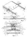
- the fastening system comprises according to the Fig. 1 to 3 a plurality of profile bars 1 with a rectangular, in particular square, cross-section, which is essentially bounded by a top 2, a bottom 3 and two longitudinal sides 4.
- a top 2 a bottom 3 and two longitudinal sides 4.
- two edge-side interventions 6 in the longitudinal sides 4 in the region of the top and bottom 2, 3 are each formed in the corner region of the profile bar T-profiles 7, which are designed either solid or filigree web structure as a function of the manufacturing process for producing the profile bar 1.
- the undercut Befest Trentsnuten 5 and the longitudinal-side interventions 6 form undercuts 8, which are received by Ein concertuten 9 of the fastener 10.
- a flat profile 11 is provided with two peripheral through holes 12, depart from the base of two parallel spaced guide tabs 13 which are dimensioned such that they engage in the longitudinal engagement of the profiled bar 1 6.
- a flange 14 extends beyond the guide lugs 13 perpendicular.
- the flat profile 11 can be attached via the through holes 12 by means of screws or rivets or by welding to a profile bar 1 or any other substrate.
- the fastener 10 may be provided as a unit with a screw 16 and a clamping member 17 fixed thereto and has a substantially rectangular cross-section, with a thread 18 oriented perpendicular to the bases and hook-in grooves 9 of the fastener 10 being provided for the screw 16 ,
- a parallel aligned Ein beneficiauten 9 which cooperate with the undercuts 8 of the profile bar 1, go from the one base two spaced apart hooks 19, 20, wherein back legs 21 of the fastening hooks 19, 20 are integrally formed on the base and hook legs 22 to Formation of Ein beneficiauten 9 point in the same direction.
- the back leg 21 of the first attachment hook 19 forms an extension of an end face 23 of the fastener 10 and the free end of the hook leg 22 of the second attachment hook 20 terminates in a plane with the opposite end face 23.
- the back leg 20 of the second attachment hook 20 is spaced from the hook leg 22 of the first attachment hook 19.
- the screw 16 connected to the fastening element 10 projects through a through-bore 24 and is screwed into a nut 26 received in a rotationally fixed manner in an undercut groove 25.
- the screw 16 may have a length in order to fasten the fastening element 10 to the profile bar 1 in a clamping manner by acting with its free end on the base of the fastening groove 5.
- the substantially U-shaped clamping member 17 which has at the free ends of its U-legs 29 each have a lug 30 to a solar module 31 through the force exerted by the screw 16 clamping force to press against the profile element 10 holding the fastener 10.
- any other flat objects such as cladding for facades, billboards or the like can be attached.
- At least two profiled bars 1 are arranged parallel to each other on a substrate or frame fixed and fitted with flat profiles 11, wherein between the guide lugs 13 of aligned flat sections 11 further profiled bars 1 inserted perpendicular to the already defined profile bars 1 and for example by means the flanges 14 of the flat profiles 11 through outstanding transverse screws 15 are secured against displacement.
- fasteners 10 is arranged with associated clamping elements 17, wherein the screw 16 of each fastener 10 is first screwed so far into the nut 26 that its free end does not protrude into the mounting groove 5.
- the screw 16 is screwed into the nut 26 so far that it projects into the mounting groove 5, after which the fastener 10 is not aushakbar from the profile bar 1 but is still displaced.
- the corresponding fastening elements 10 are pushed to the solar module 31 and the solar module 31, which may be formed as a thermal solar element or photovoltaic element, fixed by tightening the screw 16 and associated effect of the clamping element 17.
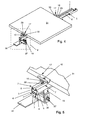
- a profile bar 1 is attached by means of roof hooks 32 to rafters 33 of a rooftop 34 covered with brick 34, first in a known manner, the roof hooks 32 are aligned with each other.
- a mounting bracket 36 is arranged by a screw connection 37, in which one leg 38 engages the screw 16 of the fastening element 10 designed as a threaded pin 39 and is fixed by a nut 40.
- a profiled bar 1 with a flat profile 11 for example, on a flat roof, or covered with a sheet metal roof having a plurality of through holes 12 defining each of its longitudinal sides.
- the thread 18 for the screw 16 is provided directly in the fastener 10.
- the profile bar 1 according to Fig. 10 has a rectangular cross-section and is provided in the region of its top 2 and bottom 3 each with two undercut Befest Trentsnuten 5 and two edge-side interventions 6, including three T-profiles 7 are formed parallel and spaced from each other.
- the longitudinal sides 4 of the profile bar 1 each have a T-profile 7 for forming an undercut fastening groove 5 and a peripheral engagement 6.
- the section bar 1 rectangular in cross-section Fig. 11 are also in the upper side 2 and 3 underside each two undercut Befest onlysnuten 5 and two edge-side interventions 6 are provided, which are formed by three parallel and spaced from each other integrally formed T-profiles 7.
- each longitudinal side 4 two parallel and spaced-apart T-profiles 7 are provided for the formation of two undercut fastening grooves 5.
- the substantially H-shaped profile bar 1 after Fig. 12 is in the Area of the top 2 and bottom 3 each provided an undercut mounting groove 5 and two edge-side interventions 6, which are formed by the molded T-profiles 7.
- the Befest Trentsnuten 5 and interventions 6 serve the purposes explained above and below.
- Fig. 13 is a profiled bar 1 with the flat profile 11, for example, on a flat roof, or covered with a sheet metal roof, set.
- the flat profile 11 has the outgoing from its support surface guide lugs 13, one of which is designed hook-shaped in cross-section and the other merges into the flange.
- Both guide lugs 13 cooperate with the undercuts 8 in the region of the associated T-profiles 7 of the profile bar 1, which is provided on its side opposite the flat profile with the fastening element 10, which carries the clamping element 17 by means of the screw 16.
- a compression spring 28 is arranged on the screw 16, which holds the clamping element 17 to the fastening element 10 and thus holds in a position which facilitates the assembly of the solar module 31.
Landscapes
- Engineering & Computer Science (AREA)
- General Engineering & Computer Science (AREA)
- Mechanical Engineering (AREA)
- Sustainable Development (AREA)
- Sustainable Energy (AREA)
- Thermal Sciences (AREA)
- Chemical & Material Sciences (AREA)
- Combustion & Propulsion (AREA)
- Physics & Mathematics (AREA)
- Life Sciences & Earth Sciences (AREA)
- Architecture (AREA)
- Civil Engineering (AREA)
- Structural Engineering (AREA)
- Roof Covering Using Slabs Or Stiff Sheets (AREA)
Claims (13)
- Elément de fixation quadratique de section transversale en particulier rectangulaire, auquel est associé un filetage (18), orienté perpendiculairement aux faces de base, pour une vis (16), deux crochets de fixation (19, 20) espacés l'un par rapport à l'autre partant depuis une face de base de l'élément de fixation (10), s'étendant sur la largeur de l'élément de fixation (10) et constituant des rainures d'accrochage (9) orientées parallèlement, caractérisé en ce que la branche arrière (21) du premier crochet de fixation (19) forme un prolongement d'un côté frontal (23) de l'élément de fixation (10) et l'extrémité libre de la branche de crochet (22) du deuxième crochet de fixation (20) se termine dans un plan avec le côté frontal opposé (23), la branche arrière (21) du deuxième crochet de fixation (20) étant de préférence adjacente au filetage (18) pour la vis (16).
- Elément de fixation selon la revendication 1, caractérisé en ce que les crochets de fixation (19, 20) partent avec leurs branches arrière (21) depuis la face de base et les branches de crochet (22) pour la formation des rainures d'accrochage (9) sont tournées dans la même direction.
- Elément de fixation selon la revendication 1, caractérisé en ce que le filetage (18) fait partie d'un écrou (26) qui est reçu de manière solidaire en rotation dans une rainure en contre-dépouille (25) et la surface d'appui (27) opposée à la surface de base tournée vers les rainures d'accrochage (9) présente un alésage traversant (24) pour la vis (16).
- Système de fixation comprenant un élément de fixation (10) selon la revendication 1 et une barre profilée (1), qui présente au moins deux contre-dépouilles (8) correspondant aux rainures d'accrochage (9).
- Système de fixation selon la revendication 4, caractérisé en ce que les contre-dépouilles (8) sont formées par deux rainures parallèles dans un profilé creux de forme quadratique ou par au moins une rainure de fixation (5) en contre-dépouille et notamment par une partie d'engagement associée (6), de préférence du côté du bord.
- Système de fixation selon la revendication 4 ou 5, caractérisé en ce que la barre profilée (1) présente une section transversale rectangulaire qui est limitée essentiellement par un côté supérieur (2), un côté inférieur (3) et deux côtés longitudinaux (4), au moins un profilé en T (7) étant à chaque fois formé pour réaliser au moins une rainure de fixation (5) et/ou au moins une partie d'engagement (6) dans la région du côté supérieur (2) et/ou du côté inférieur (3) et/ou des côtés longitudinaux (4).
- Système de fixation selon l'une quelconque des revendications 4 à 6, caractérisé en ce que la rainure ou la rainure de fixation (5) recevant le deuxième crochet de fixation (20) de l'élément de fixation (10) est dimensionnée en largeur de telle sorte que la vis (16) puisse être vissée.
- Système de fixation selon l'une quelconque des revendications 4 à 7, caractérisé en ce qu'un profilé plat (11) avec plusieurs alésages traversants (12) du côté du bord présente deux ergots de guidage (13) espacés parallèlement l'un à l'autre pour la barre profilée (1), les ergots de guidage (13) étant de préférence dimensionnés pour être introduits dans les parties d'engagement (6) du côté du bord de la barre profilée (1) et avantageusement une bride (14) s'étendant perpendiculairement au-delà de l'un des ergots de guidage (13) étant façonnée sur le profilé plat (11).
- Système de fixation selon l'une quelconque des revendications 4 à 7, caractérisé en ce qu'un crochet de toit (32) est accouplé à l'élément de fixation (10), notamment par le biais d'un coin de montage (36) qui est connecté d'une part au crochet de toit (32) et d'autre part à l'élément de fixation (10).
- Système de fixation selon l'une quelconque des revendications 4 à 7, caractérisé en ce que l'élément de fixation (10) est connecté à un élément de serrage (17) soit en forme de crochet, soit essentiellement en forme de U.
- Système de fixation selon la revendication 10, caractérisé en ce que l'élément de serrage (17) retient au moins un objet sur la barre profilée (1), notamment au moyen de la vis (16) avec laquelle l'élément de fixation (10) est fixé.
- Système de fixation selon la revendication 10 ou 11, caractérisé en ce que l'élément de serrage (17) présente au moins une pièce (30) qui repose sur l'objet à retenir, l'élément de serrage (17) étant de préférence maintenu au moyen d'une rondelle de serrage ou d'un ressort enfilé sur la vis (16) à distance par rapport à l'élément de fixation (10).
- Système de fixation selon l'une quelconque des revendications 5 à 14, caractérisé en ce qu'un module solaire (31) peut être fixé.
Applications Claiming Priority (1)
| Application Number | Priority Date | Filing Date | Title |
|---|---|---|---|
| DE102009030799A DE102009030799A1 (de) | 2009-06-27 | 2009-06-27 | Befestigungselement |
Publications (2)
| Publication Number | Publication Date |
|---|---|
| EP2267320A1 EP2267320A1 (fr) | 2010-12-29 |
| EP2267320B1 true EP2267320B1 (fr) | 2013-03-06 |
Family
ID=41720225
Family Applications (1)
| Application Number | Title | Priority Date | Filing Date |
|---|---|---|---|
| EP10006577A Active EP2267320B1 (fr) | 2009-06-27 | 2010-06-24 | Elément de fixation |
Country Status (2)
| Country | Link |
|---|---|
| EP (1) | EP2267320B1 (fr) |
| DE (2) | DE102009030799A1 (fr) |
Families Citing this family (21)
| Publication number | Priority date | Publication date | Assignee | Title |
|---|---|---|---|---|
| FR2962797B1 (fr) * | 2010-07-19 | 2014-02-14 | Tenesol | Structure de montage d'un panneau de recuperation d'energie solaire sur un support, systeme comprenant une telle structure, installation comprenant un tel systeme, procede de montage d'un systeme de recuperation d'energie solaire sur un support |
| DE102010047739A1 (de) * | 2010-10-08 | 2012-04-12 | Rehau Ag + Co. | Einlegeprofil zur Montage von Halterprofilen für plattenförmige Module sowie dieses umfassender mehrteiliger Rahmen |
| DE102010060666A1 (de) | 2010-11-19 | 2012-05-24 | Georg Kreitmair | Befestigungssystem |
| DE202010012937U1 (de) | 2010-11-19 | 2011-01-20 | Kreitmair, Georg | Befestigungssystem |
| FR2968069A1 (fr) * | 2010-11-29 | 2012-06-01 | 3I Plus | Ensemble de fixation d'un panneau solaire sur un batiment, et toiture l'integrant |
| GR20110100244A (el) * | 2011-04-19 | 2012-11-22 | Rama Ανωνυμη Βιομηχανικη Εμπορικη Εισαγωγικη Εταιρεια Μεταλλικων Κατασκευων, | Συστημα εδρασης αντικειμενων |
| DE102011084215A1 (de) * | 2011-06-07 | 2012-12-13 | Mounting Systems Gmbh | Befestigungssystem und Befestigungsanordnung für eine Solarmodulanordnung sowie Befestigerfassung und Befestigeradapter |
| US9160273B2 (en) | 2011-07-08 | 2015-10-13 | Unirac, Inc. | Universal end clamp |
| EP2810000A1 (fr) * | 2012-02-03 | 2014-12-10 | IDEEMATEC Deutschland GmbH | Système de fixation pour modules solaires |
| ITTO20120280A1 (it) * | 2012-03-30 | 2013-10-01 | Thesan S P A | Sistema di fissaggio, in particolare per fissare moduli fotovoltaici su tetti con copertura di lamiera grecata |
| DE202012012462U1 (de) | 2012-12-20 | 2013-03-04 | Mounting Systems Gmbh | Befestigungssystem zur Montage von Solarmodulen |
| DE202014101153U1 (de) * | 2014-03-13 | 2014-05-07 | Franz Stangl | Befestigungshaken und Befestigungssystem zum Befestigen von Modulen an einer Unterkonstruktion |
| US10547270B2 (en) | 2016-02-12 | 2020-01-28 | Solarcity Corporation | Building integrated photovoltaic roofing assemblies and associated systems and methods |
| WO2018099601A1 (fr) * | 2016-12-02 | 2018-06-07 | Mirko Dudas | Réseau de modules solaires et procédé d'assemblage d'un réseau de modules solaires |
| US12556127B1 (en) * | 2017-09-01 | 2026-02-17 | Tamarack Solar Products, Inc. | Solar panel mounting configuration |
| DE102018006715A1 (de) * | 2018-08-27 | 2020-02-27 | Eska Automotive Gmbh | Schraubengarnitur für Aluminiumkonstruktionen und -tragwerke im Aluminiumbau |
| US11326736B2 (en) * | 2019-10-03 | 2022-05-10 | Timothy Michael Graboski | Roof-mounted equipment attachment system |
| TWI716228B (zh) * | 2019-12-20 | 2021-01-11 | 景欣股份有限公司 | 用於衍架結構的結合組件 |
| DE102022111375A1 (de) * | 2022-05-06 | 2023-11-09 | Sl Rack Gmbh | Befestigungsvorrichtung |
| IT202300014553A1 (it) * | 2023-07-12 | 2025-01-12 | Nexus S R L | Sistema di supporto di pannelli fotovoltaici. |
| NL2035647B1 (en) * | 2023-08-21 | 2025-03-04 | Easytek Group B V | Solar panel roof mounting system |
Family Cites Families (7)
| Publication number | Priority date | Publication date | Assignee | Title |
|---|---|---|---|---|
| FR2727479B1 (fr) * | 1994-11-25 | 1997-03-28 | Renault | Dispositif de fixation notamment pour bloc optique |
| DE19848401C2 (de) * | 1998-10-21 | 2001-03-22 | Lampertz Fab Org | Variables Arbeitsplatz-Möbelsystem mit vertikalen Säulen und horizontalen Quertraversen |
| GB2380515B (en) * | 2001-10-04 | 2005-12-07 | Kenmark Ind Co Ltd | Boards combination structure |
| DE20204148U1 (de) * | 2002-03-15 | 2002-05-16 | Schüco International KG, 33609 Bielefeld | Vorrichtung zur Montage eines Kollektors und Kollektor |
| DE20308129U1 (de) * | 2003-05-24 | 2003-08-14 | Mabeg Kreuschner GmbH & Co. KG, 59494 Soest | Befestigungsvorrichtung |
| DE202004015811U1 (de) | 2004-10-13 | 2004-12-16 | Bbt Thermotechnik Gmbh | Befestigungsvorrichtung für mindestens einen Sonnenkollektor |
| DE202008011312U1 (de) | 2008-08-25 | 2008-12-04 | Ideematec Deutschland Gmbh | Verriegelungssystem zum Verriegeln von flächigen Solarmodulen |
-
2009
- 2009-06-27 DE DE102009030799A patent/DE102009030799A1/de not_active Withdrawn
- 2009-08-28 DE DE202009011708U patent/DE202009011708U1/de not_active Expired - Lifetime
-
2010
- 2010-06-24 EP EP10006577A patent/EP2267320B1/fr active Active
Also Published As
| Publication number | Publication date |
|---|---|
| EP2267320A1 (fr) | 2010-12-29 |
| DE102009030799A1 (de) | 2011-07-28 |
| DE202009011708U1 (de) | 2010-02-25 |
Similar Documents
| Publication | Publication Date | Title |
|---|---|---|
| EP2267320B1 (fr) | Elément de fixation | |
| EP2238393B1 (fr) | Système de fixation de modules solaires | |
| EP2009293B1 (fr) | Dispositif destiné à lier un rail de profilé avec un autre composant | |
| EP2691704B1 (fr) | Agencement avec modules de fixation destinés à fixer des modules solaires | |
| WO2010108288A2 (fr) | Système de fixation de plusieurs modules solaires sur un toit de bâtiment ou une façade de bâtiment et clip pour former un élément de butée sur une surface | |
| EP1734588B1 (fr) | Recouvrement de toiture | |
| EP3594427B1 (fr) | Système et procédé de fixation d'éléments de façade | |
| DE202012012290U1 (de) | Befestigungsvorrichtung zur Befestigung plattenförmiger Bauteile | |
| EP2495508A2 (fr) | Clip de maintien | |
| AT405313B (de) | Fassadenkonstruktion | |
| EP2270403A1 (fr) | Rail de support | |
| EP2423621A2 (fr) | Rail de profilé pour étrier de fixation | |
| DE202008011312U1 (de) | Verriegelungssystem zum Verriegeln von flächigen Solarmodulen | |
| DE202006018426U1 (de) | Montageschienensystem | |
| EP2006613A2 (fr) | Dispositif de fixation pour des composants de cadre installés sur un montage de structure, en particulier des modules solaires | |
| EP3043123A1 (fr) | Crochet de toit en plusieurs parties et systeme de fixation | |
| DE102012009834A1 (de) | Verbindungssystem für sich kreuzende Profile mit einer Stütze sowie Modulträger, Hauptträger, Solaranlage, Freiflächenanlage und Carport mit diesem System | |
| EP2573486A2 (fr) | Élément de serrage pour un système de fixation pour éléments en forme de plaque, système de fixation comprenant un tel élément de serrage et son utilisation | |
| EP2372269A2 (fr) | Dispositif de liaison et agencement de profilé | |
| EP2253902A2 (fr) | Ensemble de composants pour le montage de modules solaires sur un toit | |
| DE102018126983A1 (de) | System zur Befestigung von Verkleidungselementen an Bauwerken, Bauwerk mit entsprechend befestigten Verkleidungselementen sowie Verfahren zur Montage und Demontage von Verkleidungselementen | |
| WO2014169396A1 (fr) | Structure porteuse servant à fixer un module solaire sur un toit de bâtiment ou sur une façade de bâtiment | |
| DE202010012937U1 (de) | Befestigungssystem | |
| EP2261576A2 (fr) | Dispositif de fixation pour la retenue amovible de modules sous forme de plaques, notamment modules solaires ou photovoltaïques | |
| DE102011085188A1 (de) | Halteklemme und Montagesystem zum Befestigen eines oder mehrerer Flächenelemente an einem Gebäude |
Legal Events
| Date | Code | Title | Description |
|---|---|---|---|
| PUAI | Public reference made under article 153(3) epc to a published international application that has entered the european phase |
Free format text: ORIGINAL CODE: 0009012 |
|
| AK | Designated contracting states |
Kind code of ref document: A1 Designated state(s): AL AT BE BG CH CY CZ DE DK EE ES FI FR GB GR HR HU IE IS IT LI LT LU LV MC MK MT NL NO PL PT RO SE SI SK SM TR |
|
| AX | Request for extension of the european patent |
Extension state: BA ME RS |
|
| 17P | Request for examination filed |
Effective date: 20110607 |
|
| 17Q | First examination report despatched |
Effective date: 20120228 |
|
| GRAP | Despatch of communication of intention to grant a patent |
Free format text: ORIGINAL CODE: EPIDOSNIGR1 |
|
| GRAS | Grant fee paid |
Free format text: ORIGINAL CODE: EPIDOSNIGR3 |
|
| GRAA | (expected) grant |
Free format text: ORIGINAL CODE: 0009210 |
|
| AK | Designated contracting states |
Kind code of ref document: B1 Designated state(s): AL AT BE BG CH CY CZ DE DK EE ES FI FR GB GR HR HU IE IS IT LI LT LU LV MC MK MT NL NO PL PT RO SE SI SK SM TR |
|
| REG | Reference to a national code |
Ref country code: GB Ref legal event code: FG4D Free format text: NOT ENGLISH |
|
| REG | Reference to a national code |
Ref country code: CH Ref legal event code: EP Ref country code: AT Ref legal event code: REF Ref document number: 599782 Country of ref document: AT Kind code of ref document: T Effective date: 20130315 |
|
| REG | Reference to a national code |
Ref country code: IE Ref legal event code: FG4D Free format text: LANGUAGE OF EP DOCUMENT: GERMAN |
|
| REG | Reference to a national code |
Ref country code: DE Ref legal event code: R096 Ref document number: 502010002380 Country of ref document: DE Effective date: 20130502 |
|
| PG25 | Lapsed in a contracting state [announced via postgrant information from national office to epo] |
Ref country code: ES Free format text: LAPSE BECAUSE OF FAILURE TO SUBMIT A TRANSLATION OF THE DESCRIPTION OR TO PAY THE FEE WITHIN THE PRESCRIBED TIME-LIMIT Effective date: 20130617 Ref country code: LT Free format text: LAPSE BECAUSE OF FAILURE TO SUBMIT A TRANSLATION OF THE DESCRIPTION OR TO PAY THE FEE WITHIN THE PRESCRIBED TIME-LIMIT Effective date: 20130306 Ref country code: NO Free format text: LAPSE BECAUSE OF FAILURE TO SUBMIT A TRANSLATION OF THE DESCRIPTION OR TO PAY THE FEE WITHIN THE PRESCRIBED TIME-LIMIT Effective date: 20130606 Ref country code: SE Free format text: LAPSE BECAUSE OF FAILURE TO SUBMIT A TRANSLATION OF THE DESCRIPTION OR TO PAY THE FEE WITHIN THE PRESCRIBED TIME-LIMIT Effective date: 20130306 Ref country code: BG Free format text: LAPSE BECAUSE OF FAILURE TO SUBMIT A TRANSLATION OF THE DESCRIPTION OR TO PAY THE FEE WITHIN THE PRESCRIBED TIME-LIMIT Effective date: 20130606 |
|
| REG | Reference to a national code |
Ref country code: NL Ref legal event code: T3 |
|
| REG | Reference to a national code |
Ref country code: LT Ref legal event code: MG4D |
|
| PG25 | Lapsed in a contracting state [announced via postgrant information from national office to epo] |
Ref country code: FI Free format text: LAPSE BECAUSE OF FAILURE TO SUBMIT A TRANSLATION OF THE DESCRIPTION OR TO PAY THE FEE WITHIN THE PRESCRIBED TIME-LIMIT Effective date: 20130306 Ref country code: LV Free format text: LAPSE BECAUSE OF FAILURE TO SUBMIT A TRANSLATION OF THE DESCRIPTION OR TO PAY THE FEE WITHIN THE PRESCRIBED TIME-LIMIT Effective date: 20130306 Ref country code: GR Free format text: LAPSE BECAUSE OF FAILURE TO SUBMIT A TRANSLATION OF THE DESCRIPTION OR TO PAY THE FEE WITHIN THE PRESCRIBED TIME-LIMIT Effective date: 20130607 Ref country code: SI Free format text: LAPSE BECAUSE OF FAILURE TO SUBMIT A TRANSLATION OF THE DESCRIPTION OR TO PAY THE FEE WITHIN THE PRESCRIBED TIME-LIMIT Effective date: 20130306 |
|
| PG25 | Lapsed in a contracting state [announced via postgrant information from national office to epo] |
Ref country code: HR Free format text: LAPSE BECAUSE OF FAILURE TO SUBMIT A TRANSLATION OF THE DESCRIPTION OR TO PAY THE FEE WITHIN THE PRESCRIBED TIME-LIMIT Effective date: 20130306 |
|
| PG25 | Lapsed in a contracting state [announced via postgrant information from national office to epo] |
Ref country code: PT Free format text: LAPSE BECAUSE OF FAILURE TO SUBMIT A TRANSLATION OF THE DESCRIPTION OR TO PAY THE FEE WITHIN THE PRESCRIBED TIME-LIMIT Effective date: 20130708 Ref country code: CZ Free format text: LAPSE BECAUSE OF FAILURE TO SUBMIT A TRANSLATION OF THE DESCRIPTION OR TO PAY THE FEE WITHIN THE PRESCRIBED TIME-LIMIT Effective date: 20130306 Ref country code: RO Free format text: LAPSE BECAUSE OF FAILURE TO SUBMIT A TRANSLATION OF THE DESCRIPTION OR TO PAY THE FEE WITHIN THE PRESCRIBED TIME-LIMIT Effective date: 20130306 Ref country code: SK Free format text: LAPSE BECAUSE OF FAILURE TO SUBMIT A TRANSLATION OF THE DESCRIPTION OR TO PAY THE FEE WITHIN THE PRESCRIBED TIME-LIMIT Effective date: 20130306 Ref country code: IS Free format text: LAPSE BECAUSE OF FAILURE TO SUBMIT A TRANSLATION OF THE DESCRIPTION OR TO PAY THE FEE WITHIN THE PRESCRIBED TIME-LIMIT Effective date: 20130706 Ref country code: EE Free format text: LAPSE BECAUSE OF FAILURE TO SUBMIT A TRANSLATION OF THE DESCRIPTION OR TO PAY THE FEE WITHIN THE PRESCRIBED TIME-LIMIT Effective date: 20130306 |
|
| PG25 | Lapsed in a contracting state [announced via postgrant information from national office to epo] |
Ref country code: PL Free format text: LAPSE BECAUSE OF FAILURE TO SUBMIT A TRANSLATION OF THE DESCRIPTION OR TO PAY THE FEE WITHIN THE PRESCRIBED TIME-LIMIT Effective date: 20130306 |
|
| PLBE | No opposition filed within time limit |
Free format text: ORIGINAL CODE: 0009261 |
|
| STAA | Information on the status of an ep patent application or granted ep patent |
Free format text: STATUS: NO OPPOSITION FILED WITHIN TIME LIMIT |
|
| PG25 | Lapsed in a contracting state [announced via postgrant information from national office to epo] |
Ref country code: MC Free format text: LAPSE BECAUSE OF FAILURE TO SUBMIT A TRANSLATION OF THE DESCRIPTION OR TO PAY THE FEE WITHIN THE PRESCRIBED TIME-LIMIT Effective date: 20130306 Ref country code: DK Free format text: LAPSE BECAUSE OF FAILURE TO SUBMIT A TRANSLATION OF THE DESCRIPTION OR TO PAY THE FEE WITHIN THE PRESCRIBED TIME-LIMIT Effective date: 20130306 |
|
| 26N | No opposition filed |
Effective date: 20131209 |
|
| PG25 | Lapsed in a contracting state [announced via postgrant information from national office to epo] |
Ref country code: IT Free format text: LAPSE BECAUSE OF FAILURE TO SUBMIT A TRANSLATION OF THE DESCRIPTION OR TO PAY THE FEE WITHIN THE PRESCRIBED TIME-LIMIT Effective date: 20130306 |
|
| REG | Reference to a national code |
Ref country code: DE Ref legal event code: R097 Ref document number: 502010002380 Country of ref document: DE Effective date: 20131209 |
|
| REG | Reference to a national code |
Ref country code: IE Ref legal event code: MM4A |
|
| PG25 | Lapsed in a contracting state [announced via postgrant information from national office to epo] |
Ref country code: IE Free format text: LAPSE BECAUSE OF NON-PAYMENT OF DUE FEES Effective date: 20130624 |
|
| PG25 | Lapsed in a contracting state [announced via postgrant information from national office to epo] |
Ref country code: MT Free format text: LAPSE BECAUSE OF FAILURE TO SUBMIT A TRANSLATION OF THE DESCRIPTION OR TO PAY THE FEE WITHIN THE PRESCRIBED TIME-LIMIT Effective date: 20130306 |
|
| PG25 | Lapsed in a contracting state [announced via postgrant information from national office to epo] |
Ref country code: SM Free format text: LAPSE BECAUSE OF FAILURE TO SUBMIT A TRANSLATION OF THE DESCRIPTION OR TO PAY THE FEE WITHIN THE PRESCRIBED TIME-LIMIT Effective date: 20130306 |
|
| REG | Reference to a national code |
Ref country code: FR Ref legal event code: PLFP Year of fee payment: 6 |
|
| PG25 | Lapsed in a contracting state [announced via postgrant information from national office to epo] |
Ref country code: CY Free format text: LAPSE BECAUSE OF FAILURE TO SUBMIT A TRANSLATION OF THE DESCRIPTION OR TO PAY THE FEE WITHIN THE PRESCRIBED TIME-LIMIT Effective date: 20130306 Ref country code: TR Free format text: LAPSE BECAUSE OF FAILURE TO SUBMIT A TRANSLATION OF THE DESCRIPTION OR TO PAY THE FEE WITHIN THE PRESCRIBED TIME-LIMIT Effective date: 20130306 |
|
| PG25 | Lapsed in a contracting state [announced via postgrant information from national office to epo] |
Ref country code: HU Free format text: LAPSE BECAUSE OF FAILURE TO SUBMIT A TRANSLATION OF THE DESCRIPTION OR TO PAY THE FEE WITHIN THE PRESCRIBED TIME-LIMIT; INVALID AB INITIO Effective date: 20100624 Ref country code: MK Free format text: LAPSE BECAUSE OF FAILURE TO SUBMIT A TRANSLATION OF THE DESCRIPTION OR TO PAY THE FEE WITHIN THE PRESCRIBED TIME-LIMIT Effective date: 20130306 |
|
| PGFP | Annual fee paid to national office [announced via postgrant information from national office to epo] |
Ref country code: GB Payment date: 20150623 Year of fee payment: 6 |
|
| PGFP | Annual fee paid to national office [announced via postgrant information from national office to epo] |
Ref country code: FR Payment date: 20150623 Year of fee payment: 6 |
|
| GBPC | Gb: european patent ceased through non-payment of renewal fee |
Effective date: 20160624 |
|
| REG | Reference to a national code |
Ref country code: FR Ref legal event code: ST Effective date: 20170228 |
|
| PG25 | Lapsed in a contracting state [announced via postgrant information from national office to epo] |
Ref country code: FR Free format text: LAPSE BECAUSE OF NON-PAYMENT OF DUE FEES Effective date: 20160630 |
|
| PG25 | Lapsed in a contracting state [announced via postgrant information from national office to epo] |
Ref country code: GB Free format text: LAPSE BECAUSE OF NON-PAYMENT OF DUE FEES Effective date: 20160624 |
|
| PGFP | Annual fee paid to national office [announced via postgrant information from national office to epo] |
Ref country code: LU Payment date: 20170622 Year of fee payment: 8 Ref country code: BE Payment date: 20170621 Year of fee payment: 8 Ref country code: AT Payment date: 20170620 Year of fee payment: 8 Ref country code: NL Payment date: 20170621 Year of fee payment: 8 |
|
| PG25 | Lapsed in a contracting state [announced via postgrant information from national office to epo] |
Ref country code: AL Free format text: LAPSE BECAUSE OF FAILURE TO SUBMIT A TRANSLATION OF THE DESCRIPTION OR TO PAY THE FEE WITHIN THE PRESCRIBED TIME-LIMIT Effective date: 20130306 |
|
| REG | Reference to a national code |
Ref country code: NL Ref legal event code: MM Effective date: 20180701 |
|
| REG | Reference to a national code |
Ref country code: AT Ref legal event code: MM01 Ref document number: 599782 Country of ref document: AT Kind code of ref document: T Effective date: 20180624 |
|
| REG | Reference to a national code |
Ref country code: BE Ref legal event code: MM Effective date: 20180630 |
|
| PG25 | Lapsed in a contracting state [announced via postgrant information from national office to epo] |
Ref country code: LU Free format text: LAPSE BECAUSE OF NON-PAYMENT OF DUE FEES Effective date: 20180624 Ref country code: NL Free format text: LAPSE BECAUSE OF NON-PAYMENT OF DUE FEES Effective date: 20180701 |
|
| PG25 | Lapsed in a contracting state [announced via postgrant information from national office to epo] |
Ref country code: AT Free format text: LAPSE BECAUSE OF NON-PAYMENT OF DUE FEES Effective date: 20180624 |
|
| PG25 | Lapsed in a contracting state [announced via postgrant information from national office to epo] |
Ref country code: BE Free format text: LAPSE BECAUSE OF NON-PAYMENT OF DUE FEES Effective date: 20180630 |
|
| P01 | Opt-out of the competence of the unified patent court (upc) registered |
Effective date: 20230705 |
|
| PGFP | Annual fee paid to national office [announced via postgrant information from national office to epo] |
Ref country code: CH Payment date: 20240701 Year of fee payment: 15 |
|
| PGFP | Annual fee paid to national office [announced via postgrant information from national office to epo] |
Ref country code: DE Payment date: 20250618 Year of fee payment: 16 |
|
| REG | Reference to a national code |
Ref country code: CH Ref legal event code: H13 Free format text: ST27 STATUS EVENT CODE: U-0-0-H10-H13 (AS PROVIDED BY THE NATIONAL OFFICE) Effective date: 20260127 |
|
| PG25 | Lapsed in a contracting state [announced via postgrant information from national office to epo] |
Ref country code: CH Free format text: LAPSE BECAUSE OF NON-PAYMENT OF DUE FEES Effective date: 20250630 |