EP2267565A2 - System und Verfahren zur Bestimmung des optimalen Bearbeitungsverfahren - Google Patents
System und Verfahren zur Bestimmung des optimalen Bearbeitungsverfahren Download PDFInfo
- Publication number
- EP2267565A2 EP2267565A2 EP10166644A EP10166644A EP2267565A2 EP 2267565 A2 EP2267565 A2 EP 2267565A2 EP 10166644 A EP10166644 A EP 10166644A EP 10166644 A EP10166644 A EP 10166644A EP 2267565 A2 EP2267565 A2 EP 2267565A2
- Authority
- EP
- European Patent Office
- Prior art keywords
- tooling
- determining
- tool
- shape
- optimal
- Prior art date
- Legal status (The legal status is an assumption and is not a legal conclusion. Google has not performed a legal analysis and makes no representation as to the accuracy of the status listed.)
- Ceased
Links
Images


Classifications
-
- G—PHYSICS
- G05—CONTROLLING; REGULATING
- G05B—CONTROL OR REGULATING SYSTEMS IN GENERAL; FUNCTIONAL ELEMENTS OF SUCH SYSTEMS; MONITORING OR TESTING ARRANGEMENTS FOR SUCH SYSTEMS OR ELEMENTS
- G05B19/00—Program-control systems
- G05B19/02—Program-control systems electric
- G05B19/18—Numerical control [NC], i.e. automatically operating machines, in particular machine tools, e.g. in a manufacturing environment, so as to execute positioning, movement or co-ordinated operations by means of program data in numerical form
- G05B19/4093—Numerical control [NC], i.e. automatically operating machines, in particular machine tools, e.g. in a manufacturing environment, so as to execute positioning, movement or co-ordinated operations by means of program data in numerical form characterised by part programming, e.g. entry of geometrical information as taken from a technical drawing, combining this with machining and material information to obtain control information, named part program, for the NC machine
- G05B19/40937—Numerical control [NC], i.e. automatically operating machines, in particular machine tools, e.g. in a manufacturing environment, so as to execute positioning, movement or co-ordinated operations by means of program data in numerical form characterised by part programming, e.g. entry of geometrical information as taken from a technical drawing, combining this with machining and material information to obtain control information, named part program, for the NC machine concerning programming of machining or material parameters, pocket machining
- G05B19/40938—Tool management
-
- G—PHYSICS
- G05—CONTROLLING; REGULATING
- G05B—CONTROL OR REGULATING SYSTEMS IN GENERAL; FUNCTIONAL ELEMENTS OF SUCH SYSTEMS; MONITORING OR TESTING ARRANGEMENTS FOR SUCH SYSTEMS OR ELEMENTS
- G05B19/00—Program-control systems
- G05B19/02—Program-control systems electric
- G05B19/18—Numerical control [NC], i.e. automatically operating machines, in particular machine tools, e.g. in a manufacturing environment, so as to execute positioning, movement or co-ordinated operations by means of program data in numerical form
- G05B19/4097—Numerical control [NC], i.e. automatically operating machines, in particular machine tools, e.g. in a manufacturing environment, so as to execute positioning, movement or co-ordinated operations by means of program data in numerical form characterised by using design data to control NC machines, e.g. CAD/CAM
-
- G—PHYSICS
- G05—CONTROLLING; REGULATING
- G05B—CONTROL OR REGULATING SYSTEMS IN GENERAL; FUNCTIONAL ELEMENTS OF SUCH SYSTEMS; MONITORING OR TESTING ARRANGEMENTS FOR SUCH SYSTEMS OR ELEMENTS
- G05B2219/00—Program-control systems
- G05B2219/30—Nc systems
- G05B2219/36—Nc in input of data, input key till input tape
- G05B2219/36289—Cutting, machining conditions by optimisation of time, cost, accuracy
-
- G—PHYSICS
- G05—CONTROLLING; REGULATING
- G05B—CONTROL OR REGULATING SYSTEMS IN GENERAL; FUNCTIONAL ELEMENTS OF SUCH SYSTEMS; MONITORING OR TESTING ARRANGEMENTS FOR SUCH SYSTEMS OR ELEMENTS
- G05B2219/00—Program-control systems
- G05B2219/30—Nc systems
- G05B2219/36—Nc in input of data, input key till input tape
- G05B2219/36296—Order, select, determine, change machining sequence, order
-
- G—PHYSICS
- G05—CONTROLLING; REGULATING
- G05B—CONTROL OR REGULATING SYSTEMS IN GENERAL; FUNCTIONAL ELEMENTS OF SUCH SYSTEMS; MONITORING OR TESTING ARRANGEMENTS FOR SUCH SYSTEMS OR ELEMENTS
- G05B2219/00—Program-control systems
- G05B2219/30—Nc systems
- G05B2219/36—Nc in input of data, input key till input tape
- G05B2219/36352—Select tool as function of part shape, number of grooves and groove width
-
- G—PHYSICS
- G05—CONTROLLING; REGULATING
- G05B—CONTROL OR REGULATING SYSTEMS IN GENERAL; FUNCTIONAL ELEMENTS OF SUCH SYSTEMS; MONITORING OR TESTING ARRANGEMENTS FOR SUCH SYSTEMS OR ELEMENTS
- G05B2219/00—Program-control systems
- G05B2219/30—Nc systems
- G05B2219/36—Nc in input of data, input key till input tape
- G05B2219/36357—Tool line up, select right order of tool, optimal tool order loading, tool file
-
- Y—GENERAL TAGGING OF NEW TECHNOLOGICAL DEVELOPMENTS; GENERAL TAGGING OF CROSS-SECTIONAL TECHNOLOGIES SPANNING OVER SEVERAL SECTIONS OF THE IPC; TECHNICAL SUBJECTS COVERED BY FORMER USPC CROSS-REFERENCE ART COLLECTIONS [XRACs] AND DIGESTS
- Y02—TECHNOLOGIES OR APPLICATIONS FOR MITIGATION OR ADAPTATION AGAINST CLIMATE CHANGE
- Y02P—CLIMATE CHANGE MITIGATION TECHNOLOGIES IN THE PRODUCTION OR PROCESSING OF GOODS
- Y02P90/00—Enabling technologies with a potential contribution to greenhouse gas [GHG] emissions mitigation
- Y02P90/02—Total factory control, e.g. smart factories, flexible manufacturing systems [FMS] or integrated manufacturing systems [IMS]
Definitions
- the invention relates to a system and method that are used to determine an optimal process for forming a product shape from a material shape.
- JP-A-11-235646 A system that determines a machining process is, for example, described in Japanese Patent Application Publication No. 11-235646 ( JP-A-11-235646 ).
- process candidates are selected in descending order of machining efficiency for a plurality of toolings each composed of a predetermined combination of a tool and a holder to thereby determine an optimal machining process.
- the invention provides a process determining system and method that are able to determine a further optimal machining process.
- a machined shape using a basic tooling or basic tooling template of each machining efficiency group.
- the machined shape is a reference shape that is a reference according to each machining efficiency group.
- a combination of a tool, a holder and a tool projection length, that is able to form a material into the reference shape and that has the highest machining efficiency among various combinations of a tool and a holder, is determined. That is, according to the feature of an example of the invention, a combination of a tool, a holder and a tool projection length, having the highest machining efficiency, is selected from among infinite combinations of a tool, a holder and a tool projection length for each of a plurality of machining efficiency groups.
- the "machining efficiency” corresponds to a removal volume per unit time.
- tool projection length (L) / tool edge diameter (D) ( ⁇ stiffness) may be used as the machining efficiency.
- machining efficiency group means a group of which the machining efficiency falls within a predetermined range.
- an optimal tooling is determined not only for each machining efficiency group but also for each tool edge diameter. Even when the machining efficiency group is the same, the tool edge diameter may be varied. Then, by determining an optimal tooling for each machining efficiency group and each tool edge diameter, it is possible to determine a further optimal process.
- a total removal region before excluding a process candidate may be removed.
- an overlap process may be reliably excluded while the same removal region is reliably ensured.
- an overlap process may be reliably excluded so as to be able to reduce a machining time.
- changing a tool axis position is considered.
- four-axis or five-axis machining is applicable.
- not only five-axis index machining but also five-axis simultaneous machining is applicable.
- a tool axis position may be changed, a removable region varies even with the same tooling.
- a tool axis position having the largest removal volume is determined while changing the tool axis position, and then the machined shape in this state is determined. That is, an optimal process may be determined including a change in tool axis position.
- a machined shape is determined for each of a plurality of basic tooling templates. That is, an optimal process candidate is determined for each basic tooling template.
- an optimal process candidate is determined for each basic tooling template.
- the circular cylindrical shape of the basic tooling template in an inverted stepped shape, it is possible to represent a further appropriate outer shape of a combination of a tool and a holder. That is, by defining basic tooling templates using an inverted conical shape and an inverted stepped shape formed of cylindrical shapes, it is possible to determine a sufficiently appropriate process candidate using a slight number of templates.
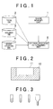
- the process determining system includes a shape memory unit 1, a tool DB(Data Base) 2, a holder DB 3, a basic tooling DB 4 and an optimal process determining unit 5.
- the shape memory unit 1 stores a material shape and a product shape created by a computer aided design (CAD) (not shown).
- CAD computer aided design
- the material shape is denoted by 11
- the product shape is denoted by 12. That is, the product shape 12 is formed from the material shape 11 by pocketing or milling in example.
- the bottom shape of a pocket portion has a deep portion and a shallow portion.
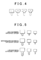
- the tool DB 2 (which is part of the tool holder information storage unit in the example) stores information of a plurality of tools.
- each of the tools is a ball end mill, and there are the plurality of tools having different edge diameters and different edge shapes.
- the "edge diameter of a tool” means the outside diameter of an operating edge portion of the tool.
- the leftmost tool has the largest edge diameter
- the second tool from the left has the second largest edge diameter
- two types of tools on the right have the smallest edge diameters.
- the shapes of the three types of tools on the left are such that a portion other than the distal end portion has a constant diameter circular cylindrical shape
- the shape of one type of tool on the right in FIG. 3 is such that a portion other than the distal end portion has a stepped circular cylindrical shape. That is, the shape of the type of tool on the right in FIG. 3 is formed of a shape having a base portion that is larger in outside diameter than the edge portion. Then, in the tool DB 2, tool numbers are respectively associated with pieces of information of the tools.
- the holder DB 3 (which is also part of the tool holder information storage unit) stores information of a plurality of holders. As shown in FIG. 4 , there are a plurality of types of holders that can respectively hold tools having different edge diameters and different edge shapes, and the holders that can hold the same tool also have multiple shapes. In the holder DB 3, holder numbers are respectively associated with pieces of information relating to the holders.
- the basic tooling DB 4 (which is also part of the basic tooling storage unit according to the example) stores a basic tooling for each of a plurality of machining efficiency groups and for each of different edge diameters of the tools.
- the "basic tooling” is a combination of a tool, a holder and a tool projection length.
- the "machining efficiency” corresponds to a removal volume per unit time. For example, when a given workpiece material is cut by a tool of a given material, tool projection length (L) / tool edge diameter (D) ( ⁇ stiffness) may be used as the machining efficiency.
- the "machining efficiency group” means a group of which the machining efficiency falls within a predetermined range.
- L/D is 5 or below
- L/D is between 5 and 10
- L/D is 10 or above.
- the optimal process determining unit 5 determines an optimal process for forming the product shape from the material shape.
- the optimal process comprises a plurality of process candidates and the sequence of the process candidates.
- each process candidate includes information of a tooling, including a tool, a holder and a tool projection length, a removal region and an index angle (tool axis position).
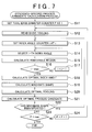
- FIG. 6 to FIG. 9 are flowcharts that show an optimal process determining method for determining the optimal process.
- the process determining unit 5 can be, for example, a processor, controller or computer, and the stored data bases (DB) can be stored in an appropriate storage medium, such as in a memory of a computer, and can be part of the same device or separate from the device including the process determining unit 5.
- the determining system can be included in the control system of the machine tool, can be a separate system, or can be a system connected to a machine tool control system. Once the process is determined, the process is carried out by the machine tool to form products shaped using the process.
- the optimal process determining unit 5 reads the product shape from the shape memory unit 1 (S1). Subsequently, the material shape is read from the shape memory unit 1 (S2). Thereafter, tool candidates are read from the tool DB 2 (S3), and holder candidates are read from the holder DB 3 (S4).
- an efficiency-specific process candidate determining process is executed for a high machining efficiency group (S5).
- a tool edge diameter counter P is set at 1 (S11).
- the counter P of the largest edge diameter for example, ⁇ 18
- the counter P of the second largest edge diameter for example, ⁇ 10
- the counter P of the third largest edge diameter for example, ⁇ 8, is set at 3.
- a basic tooling for the high machining efficiency group is read from the basic tooling DB 4 (S12). Then, the counter i of the index angle of the tool is set at 1 (S13). The index angle corresponds to the tool axis position. Thereafter, the i-th index angle is selected (S14). That is, an actual index angle is selected (as discussed further below). After that, a removable region when the material shape is machined by the basic tooling at the selected index angle is calculated (S15).
- the removable region at a certain index angle is a hatched region indicated as the removable region in FIG. 10A . That is, the above removable region may be machined without interference of the tool or the holder with a portion of a product shape.
- the removable region is a hatched region indicated as the removable region in FIG. 10B .
- step S16 it is determined whether the index angle counter i is a maximum value (S16).
- the index angle counter i is incremented by 1 (S17) and then the process is repeated from step S14. That is, for each of a plurality of index angles, a removable region of the basic tooling is calculated.
- an index angle, at which a removal volume is maximal among the plurality of removable regions is calculated (S18).
- the index angle of FIG. 10A is compared with the index angle of FIG. 10B , the index angle of FIG. 10A is selected.
- the machined shape is a shape excluding the removable region from the material shape. That is, the machined shape is a shape machined by the basic tooling from the material shape.
- an optimal tooling is determined (S20).
- the optimal tooling is able to machine the material shape into the machined shape determined in step S19 without interfering with the machined shape, and has the highest machining efficiency.
- the toolings shown in FIG. 12A and FIG. 12B are able to machine the material shape into the machined shape.
- the tooling shown in FIG. 12B has a short tool projection length and, therefore, has a high machining efficiency.
- the basic tooling is an index tooling for obtaining a predetermined machining efficiency group, and may be different from the optimal tooling selected here or may be the same in some cases.
- an optimal process candidate using the optimal tooling determined in step S20 is determined (S21).
- the optimal process candidate is information relating to a plurality of processes, each including an optimal tooling and an optimal index angle.
- step S19 it is determined whether the machined shape determined in step S19 is updated (S22).
- the process is repeated from step S13. Initially, the machined shape is newly determined, so, of course, the process is repeated from S13. In the processes from the next step S13 to step S21, the processes are executed while the initially calculated machined shape is regarded as a material shape.
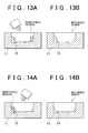
- step S21 when machining is performed using the shape shown in FIG. 11 as a material shape, the hatched region indicated as the removable region in FIG. 13A is a removable region, and the shape shown in FIG. 13B is a machined shape. Then, in step S21, this process is added to the already determined optimal process candidate. Then, in step S22, it is determined that the machined shape has been updated, so the process is repeated from step S13 again.
- machining is performed using the shape shown in FIG. 13B as a material shape.
- the hatched region indicated as the removable region in FIG. 14A is a removable region
- the shape shown in FIG. 14B is a machined shape.
- the tool edge diameter counter P is a maximum value (S23).
- the tool edge diameter counter P is incremented by 1 (S24) and then the process is repeated from step S12. That is, an optimal process candidate is determined for each of the plurality of tool edge diameters. Then, when the tool edge diameter counter P reaches the maximum value, the efficiency-specific process candidate determining process is ended.
- the efficiency-specific process candidate determining process in the case of the high machining efficiency group is executed in step S5. Subsequently, the efficiency-specific process candidate determining process in the case of the intermediate machining efficiency group is executed (S6). In addition, after that, the efficiency-specific process candidate determining process in the case of the low machining efficiency group is executed (S7). In this way, an optimal process candidate is determined for each of the plurality of different machining efficiency groups and each of the tool edge diameters.
- each of the optimal process candidates correspond to individual processes. That is, each of the individual processes includes information of a tooling, which includes a tool, a holder and a tool projection length, a removal region and an index angle (tool axis position).
- a further optimal temporary optimal process is determined on the basis of the integrated temporary optimal process. This process is shown in FIG. 8 . As shown in FIG. 8 , first, in the temporary optimal process determining process, the temporary optimal process determined in step S8 in FIG. 6 is read (S31).
- the process number counter j of the individual process of the temporary optimal process is set at 1 (S32).
- a process that excludes the j-th process from the individual processes is determined (S33).
- a total removal region when the current temporary optimal process (all the individual processes) is executed is determined (S34).
- a total removal region when the j-th process excluding process (remaining individual processes excluding the j-th process) is executed is determined (S34).
- an actual machining time when the current temporary optimal process is executed is determined (S35).
- an actual machining time when the j-th process excluding process is executed is determined (S35).
- step S36 it is determined whether the process number counter j is a maximum value (S36).
- the process number counter j is incremented by 1 (S37) and then the process is repeated from step S33. That is, a total removal region and an actual machining time are determined for each of partially excluded processes that are obtained by sequentially excluding one of the individual processes.
- the temporary optimal process is determined (updated). That is, when the plurality of optimal process candidates are partially excluded, a partially excluded process of which the total removal region coincides with the total removal region of the temporary optimal process is extracted. That is, among the partially excluded process, a partially excluded process that can remove the total removal region of the current temporary optimal process is extracted. In addition, when a plurality of partially excluded processes are extracted, the process having the shortest actual machining time among the plurality of partially excluded processes is used to update the temporary optimal process (S38).
- step S39 the process is repeated from step S31.
- the temporary optimal process read in step S31 is the temporary optimal process updated in step S38. That is, by repeating steps S31 to S38, individual processes may be excluded so that the total removal region remains unchanged and the actual machining time reduces. By so doing, individual processes having substantially overlapping removal regions are excluded.
- the temporary optimal process determined in step S38 is determined as the temporary optimal process (S40). Then, the temporary optimal process determining process is ended.
- step S9 the temporary optimal process determining process is executed. Subsequently, an optimal process determining process for determining a further optimal process is executed on the temporary optimal process (S10).
- the optimal process determining process is shown in FIG. 9 . As shown in FIG. 9 , first, in the optimal process determining process, the temporary optimal process determined in step S9 in FIG. 6 is read (S51).
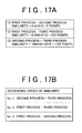
- the combinations are sorted in descending order of similarity (S54). That is, as shown in FIG. 17B , the combination of "the second process and the third process" having the highest similarity is a similarity No. 1, the combination of "the first process and the third process” having the second highest similarity is a similarity No. 2, and the combination of "the first process and the second process” having the third highest similarity is a similarity No. 3.
- an integrated process when the tooling of one of the processes of the similarity No. k is integrated into the tooling of the other one of the processes of the similarity No. k is calculated (S56). That is, an initially determined integrated process includes an integrated process obtained by integrating the tooling of the second process into the tooling of the third process and an integrated process obtained by integrating the tooling of the third process into the tooling of the second process.
- the optimal process determining unit 5 determines whether the similarity No. k is a maximum value (S59). When the similarity No. k is not a maximum value, the optimal process determining unit 5 adds 1 to the similarity No. k (S60) and then repeats the process from step S56. That is, each of the similarity Nos. is integrated in descending order, and then a total removal region and an actual machining time are determined for each of the integrated processes that can be integrated.
- an optimal process is determined from among the temporary optimal process and the plurality of integrated processes (S61).
- determination of an optimal process first, only the integrated processes that have the same total removal region as the total removal region of the temporary optimal process are extracted. After that, an optimal process is determined from among the extracted integrated processes and the temporary optimal process.
- a temporary optimal process is shown in the row (a) in the table of FIG. 18
- a process that integrates a tooling "B" of the second process into a tooling "C” of the third process among the extracted integrated processes is shown in the row (b) in the table of FIG. 18
- a process that integrates toolings "A” and "B” of the first process and second process into the tooling "C” of the third process among the extracted integrated processes is shown in the row (c) in the table of FIG. 18 .
- the removal volume of the first process is 300 mm 3
- the machining efficiency (removal volume per unit time) of the tooling "A" of the first process is 30 mm 3 /minute.
- the removal volume of the second process is 60 mm 3
- the machining efficiency of the tooling "B" of the second process is 6 mm 3 /minute.
- the removal volume of the third process is 30 mm 3
- the machining efficiency of the tooling "C" of the third process is 3 mm 3 /minute.
- the actual machining time of the first process is 10 minutes
- the actual machining time of the second process is 10 minutes
- the actual machining time of the third process is 10 minutes. That is, the actual machining time of the temporary optimal process is 30 minutes.
- the first process uses the tooling "A”
- the second process and the third process use the tooling "C”. That is, the integrated process row (b) of FIG. 18 shows the case where the tooling of the second process is integrated into the tooling of the third process.
- the actual machining time of the first process is 10 minutes
- the actual machining time of the second process is 20 minutes
- the actual machining time of the third process is 10 minutes. That is, the actual machining time of the temporary optimal process is 40 minutes.
- the integrated process of row (c) of FIG. 18 shows the case where the toolings of the first and second processes are integrated into the tooling of the third process.
- the actual machining time of the first process is 100 minutes
- the actual machining time of the second process is 20 minutes
- the actual machining time of the third process is 10 minutes. That is, the actual machining time of the temporary optimal process is 130 minutes.
- the unit integration reduction time is a value corresponding to a possession conversion time that is obtained by converting the possession of a tool and a holder by a user of a machine into a time, a tooling preparation time for setting a tool and a holder to the machine or a time consumed for the number of times of tool replacement carried out for machining.
- the unit integration reduction time is 20 minutes.
- the number of integrations is a number by which the toolings of the processes in the temporary optimal process are integrated. That is, the number of integrations in the case of row (b) of FIG. 18 is 1, and the number of integrations in the case of row (c) of FIG. 18 is 2.
- the total time of the temporary optimal process shown in row (a) of FIG. 18 is 30 minutes
- the total time of the integrated process shown in row (b) of FIG. 18 is 20 minutes
- the total time of the integrated process shown in row (c) of FIG. 18 is 90 minutes.
- the process having the shortest total time is the integrated process shown in row (b) of FIG. 18 .
- the above integrated process is determined as the optimal process.
- the optimal process By determining the optimal process as described above, it is possible to determine a further optimal process.
- the integrated process is determined to be optimal when a time obtained by multiplying the unit integration reduction time by the number of individual processes integrated is longer than the elongated actual machining time. By so doing, it is possible to achieve a reduction in total time at an actual worksite.
- a value of a unit integration reduction time so as to correspond to a possession conversion time, it is possible to reduce the number of tools and the number of holders, possessed by a user of a machine, and it is not necessary to purchase a new tool or a new holder.
- a reduction in the number of tools or the number of holders possessed enables reduction in costs of storage and management.
- a total time may be eventually reduced, and costs may be reduced.
- a value of a unit integration reduction time so as to correspond to a tooling preparation time, it is possible to reduce a total working time with a reduction in tooling preparation time.
- a value of a unit integration reduction time so as to correspond to a time consumed for the number of times of tool replacement, it is possible to reduce a total working time with a reduction in time consumed for the number of times of tool replacement.
- an element of the similarity is any one of the type of tool, the type of holder, a tool projection length and a tool edge diameter, and the similarity coefficient of each element is varied.
- a removable region is determined using the basic tooling (S15) in the efficiency-specific process candidate determining process shown in FIG. 7 .
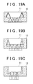
- templates shown in FIG. 19A to FIG. 19C may be used.
- these templates each have a shape that is obtained so that the vertex of a cone shape traces a machined surface of a product shape.
- the basic tooling template, as well as the above described basic tooling is set for each of the plurality of machining efficiency groups.
- the basic tooling templates respectively shown in FIG. 19A, FIG. 19B and FIG. 19C correspond to the high, intermediate and low machining efficiency groups, respectively.
- there are three types of machining efficiency groups that is, high, intermediate and low; instead, there may be two types of machining efficiency groups or four or more types of machining efficiency groups.
- one type of basic tooling template is set for each machining efficiency group.
- a plurality of basic tooling templates are set for each machining efficiency group, and machined shapes are respectively determined using the basic tooling templates to thereby make it possible to calculate optimal process candidates.
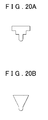
- the shapes shown in FIG. 20A and FIG. 20B are set as a plurality of basic tooling templates.
- a holder portion has a shape such that a small-diameter circular cylindrical shape and a large-diameter circular cylindrical shape are coaxially connected from a tool side (lower side in the drawing). That is, the holder portion is formed in an inverted stepped shape formed of the circular cylindrical shapes.
- the other basic tooling template has a holder portion formed in an inverted conical shape.
- the basic tooling templates shown in FIG. 20A and FIG. 20B belong to the same machining efficiency group.
- the tool projection length of the basic tooling template having the inverted stepped holder portion shown in FIG. 20A is longer than the tool projection length of the basic tooling template having the inverted conical holder portion shown in FIG. 20B . This is due to the influence of stiffness of the holder portion.
- FIG. 21A a pocket shape shown in FIG. 21A is formed.
- the pocket shape is machined by the first basic tooling template (stepped shape)
- the first basic tooling template stepped shape
- the second basic tooling template inverted conical shape
- the holder portion interferes with an edge portion as shown in FIG. 21C , it is not possible to perform machining to the deepest position of the pocket shape.
- a pocket shape shown in FIG. 22A is formed.
- the pocket shape is machined by the first basic tooling template (stepped shape)
- the holder portion interferes with an edge portion as shown in FIG. 22B
- the pocket shape is machined by the second basic tooling template (inverted conical shape)
- a tool edge diameter counter P is set at 1 (S71).
- the counter P of the largest edge diameter for example, ⁇ 18
- the counter P of the second largest edge diameter for example, ⁇ 10
- the counter P of the third largest edge diameter for example, ⁇ 8, is set at 3.
- basic tooling templates for the high machining efficiency group are read from the basic tooling DB 4 (S72).
- the basic tooling templates read here are two types, that is, the template having a stepped circular cylindrical holder portion and the template having an inverted conical holder portion.
- a template counter T is set at 1 (S73). That is, the basic tooling template having the stepped circular cylindrical holder portion shown in FIG. 20A is set.
- the counter i of the index angle of the tool is set at 1 (S74).
- the index angle corresponds to the tool axis position.
- the i-th index angle is selected (S75). That is, an actual index angle is selected.
- a removable region when the material shape is machined by the selected basic tooling at the selected index angle is calculated (S76).
- the index angle counter i is a maximum value (S77).
- the index angle counter i is incremented by 1 (S78) and then the process is repeated from step S75. That is, for each of the plurality of index angles, a removable region of the selected basic tooling template is determined.
- an index angle, at which a removal volume is maximal among a plurality of removable regions, is determined (S79).
- a shape machined at the index angle calculated in step S79 is determined (S80).
- the machined shape is a shape excluding the removable region from the material shape. That is, the machined shape is a shape machined by the basic tooling template from the material shape.
- an optimal tooling is determined (S81).
- the optimal tooling is able to machine the material shape into the machined shape determined in step S80 without interfering with the machined shape, and has the highest machining efficiency.
- an optimal process candidate using the optimal tooling determined in step S81 is determined (S82).
- the optimal process candidate is process information, including an optimal tooling and an optimal index angle.
- step S80 it is determined whether the machined shape determined in step S80 is updated (S83).
- the process is repeated from step S74.
- the machined shape is newly determined, so, of course, the process is repeated from S74.
- the processes are executed while the initially determined machined shape is regarded as a material shape.
- this process is added to the already determined optimal process candidate.
- step S83 it is determined that the machined shape has been updated, and then the process is repeated from step S74 again.
- the template counter T is a maximum value (S84).
- the template counter T is incremented by 1 (S85) and then the process is repeated from step S74. That is, an optimal process candidate is determined for each of the plurality of basic tooling templates.
- the template counter T it is determined whether the tool edge diameter counter P is a maximum value (S86).
- the tool edge diameter counter P is incremented by 1 (S87), and then the process is repeated from step S72. That is, an optimal process candidate is determined for each of the plurality of tool edge diameters and each of the plurality of basic tooling templates. Then, when the tool edge diameter counter P reaches the maximum value, the efficiency-specific process candidate determining process is ended.
- a machined shape is determined from each of the plurality of basic tooling templates. That is, an optimal process candidate is determined for each basic tooling template.
- an optimal process candidate is determined for each basic tooling template.
- the optimal process determining system intended for a five-axis machine tool that is able to change the index angle (tool axis position) is described.
- the intended five-axis machine tool may be not only a five-axis index machine tool but also a five-axis simultaneous machine tool.
- the five-axis index machine tool carries out machining so that, in a state where at least one of the rotation axes is indexed (fixed), the other rotation axes are moved.
- the five-axis simultaneous machine tool carries out machining while simultaneously controlling travel axes and rotation axes.
- the aspect of the invention may also be applied to an optimal process determining system intended for a machine tool that is able to move along only three orthogonal axes.
- This example eliminates processes regarding the index angle (tool axis position). Specifically, steps S13 to S18 and S22 in the efficiency-specific process candidate determining process shown in FIG. 7 can be eliminated.
- the other configuration is substantially the same.
Landscapes
- Engineering & Computer Science (AREA)
- Manufacturing & Machinery (AREA)
- Physics & Mathematics (AREA)
- Human Computer Interaction (AREA)
- General Physics & Mathematics (AREA)
- Automation & Control Theory (AREA)
- Geometry (AREA)
- Numerical Control (AREA)
Applications Claiming Priority (2)
| Application Number | Priority Date | Filing Date | Title |
|---|---|---|---|
| JP2009147833 | 2009-06-22 | ||
| JP2009256173A JP5441627B2 (ja) | 2009-06-22 | 2009-11-09 | 最適工程決定装置および最適工程決定方法 |
Publications (2)
| Publication Number | Publication Date |
|---|---|
| EP2267565A2 true EP2267565A2 (de) | 2010-12-29 |
| EP2267565A3 EP2267565A3 (de) | 2017-03-08 |
Family
ID=42779900
Family Applications (1)
| Application Number | Title | Priority Date | Filing Date |
|---|---|---|---|
| EP10166644.4A Ceased EP2267565A3 (de) | 2009-06-22 | 2010-06-21 | System und Verfahren zur Bestimmung des optimalen Bearbeitungsverfahren |
Country Status (3)
| Country | Link |
|---|---|
| US (1) | US8301293B2 (de) |
| EP (1) | EP2267565A3 (de) |
| JP (1) | JP5441627B2 (de) |
Cited By (1)
| Publication number | Priority date | Publication date | Assignee | Title |
|---|---|---|---|---|
| EP3497526A4 (de) * | 2016-08-09 | 2020-04-01 | Tomologic AB | System zur optimierung eines betriebs einer industriemaschine durch modifizierung einer standardisierten prozessparametereingabe |
Families Citing this family (3)
| Publication number | Priority date | Publication date | Assignee | Title |
|---|---|---|---|---|
| FR2905018B1 (fr) * | 2006-08-17 | 2008-10-10 | Peugeot Citroen Automobiles Sa | Procede de modelisation graphique tridimensionnelle |
| JP2012218111A (ja) * | 2011-04-08 | 2012-11-12 | Fanuc Ltd | 工具ホルダおよび工具ホルダへの工具取付け長さを決定する機能を備えた数値制御装置 |
| JP2014067200A (ja) * | 2012-09-26 | 2014-04-17 | Hitachi Ltd | 加工システム及び数値制御データ生成装置及び数値制御データ生成方法 |
Citations (1)
| Publication number | Priority date | Publication date | Assignee | Title |
|---|---|---|---|---|
| JPH11235646A (ja) | 1998-02-19 | 1999-08-31 | Toyota Central Res & Dev Lab Inc | 加工工程の決定方法 |
Family Cites Families (12)
| Publication number | Priority date | Publication date | Assignee | Title |
|---|---|---|---|---|
| US4509126A (en) * | 1982-06-09 | 1985-04-02 | Amca International Corporation | Adaptive control for machine tools |
| JP2798549B2 (ja) * | 1992-03-26 | 1998-09-17 | オークマ株式会社 | 内径加工工具の自動決定方法 |
| JPH06119031A (ja) * | 1992-10-07 | 1994-04-28 | Honda Motor Co Ltd | 削り残し部加工のncデータ作成方法 |
| US5465221A (en) * | 1993-12-30 | 1995-11-07 | The United States Of America As Represented By The Secretary Of The Air Force | Automated process planning for quality control inspection |
| US6136132A (en) * | 1997-03-26 | 2000-10-24 | Kinzie; Norman F. | Method and apparatus for the manufacture of three-dimensional objects |
| US6311100B1 (en) * | 1998-09-14 | 2001-10-30 | Mass. Institute Of Technology | Tool path generator for computer aided manufacturing |
| JP2001075624A (ja) * | 1999-07-01 | 2001-03-23 | Mori Seiki Co Ltd | Nc工作機械のツールパスデータ生成装置及びこれを備えた数値制御装置 |
| US7245977B1 (en) * | 2000-07-20 | 2007-07-17 | Align Technology, Inc. | Systems and methods for mass customization |
| US7392109B2 (en) * | 2000-07-31 | 2008-06-24 | Kabushiki Kaisha Toyota Chuokenkyusho | System for integrally generating NC data |
| JP2004133878A (ja) * | 2002-08-15 | 2004-04-30 | Incs Inc | プロセス遂行システム及びそのためのコンピュータプログラム |
| JP2004284002A (ja) * | 2003-01-31 | 2004-10-14 | Fujitsu Ltd | 加工制御装置 |
| JP4321548B2 (ja) * | 2005-07-14 | 2009-08-26 | Jfeスチール株式会社 | 熱間鍛造設備 |
-
2009
- 2009-11-09 JP JP2009256173A patent/JP5441627B2/ja not_active Expired - Fee Related
-
2010
- 2010-06-21 EP EP10166644.4A patent/EP2267565A3/de not_active Ceased
- 2010-06-22 US US12/820,282 patent/US8301293B2/en not_active Expired - Fee Related
Patent Citations (1)
| Publication number | Priority date | Publication date | Assignee | Title |
|---|---|---|---|---|
| JPH11235646A (ja) | 1998-02-19 | 1999-08-31 | Toyota Central Res & Dev Lab Inc | 加工工程の決定方法 |
Cited By (3)
| Publication number | Priority date | Publication date | Assignee | Title |
|---|---|---|---|---|
| EP3497526A4 (de) * | 2016-08-09 | 2020-04-01 | Tomologic AB | System zur optimierung eines betriebs einer industriemaschine durch modifizierung einer standardisierten prozessparametereingabe |
| US11156985B2 (en) | 2016-08-09 | 2021-10-26 | Tomologic Ab | System for optimization of industrial machine operation through modification of standard process parameter input |
| EP4418174A3 (de) * | 2016-08-09 | 2024-11-27 | Tomologic AB | System zur optimierung eines betriebs einer industriemaschine durch modifizierung einer standardisierten prozessparametereingabe |
Also Published As
| Publication number | Publication date |
|---|---|
| US8301293B2 (en) | 2012-10-30 |
| EP2267565A3 (de) | 2017-03-08 |
| US20100324713A1 (en) | 2010-12-23 |
| JP2011025394A (ja) | 2011-02-10 |
| JP5441627B2 (ja) | 2014-03-12 |
Similar Documents
| Publication | Publication Date | Title |
|---|---|---|
| CN101893873B (zh) | 产生用于控制机床上的刀具的控制数据的方法和装置 | |
| JP6709869B1 (ja) | 穴あけ方法及び穴あけ機 | |
| CN103842921B (zh) | 生产计划装置以及生产计划方法 | |
| Krimpenis et al. | CNC micromilling properties and optimization using genetic algorithms | |
| JP6629410B1 (ja) | Ncプログラム変換処理方法、変換用計算機、及び変換プログラム | |
| EP2267565A2 (de) | System und Verfahren zur Bestimmung des optimalen Bearbeitungsverfahren | |
| JP5595146B2 (ja) | 加工シミュレーション装置および最適工程決定装置 | |
| CN100399340C (zh) | 用于生成加工程序的方法和装置 | |
| EP2267564B1 (de) | System und Verfahren zur Bestimmung der Prozessintegration | |
| Abdou et al. | TVCAPP, tolerance verification in computer-aided process planning | |
| KR101108211B1 (ko) | 복합선반용 파트프로그래밍 장치 및 복합 공정간 동기화 프로그램 생성방법 | |
| JP5322881B2 (ja) | 加工シミュレーション装置および最適工程決定装置 | |
| KR101078800B1 (ko) | 외장형 파트프로그램 작성장치 | |
| JP5441604B2 (ja) | 最適工程決定装置および最適工程決定方法 | |
| JP4390641B2 (ja) | 多軸切削加工ユニットの設計支援装置 | |
| JP5441606B2 (ja) | 最適工程決定装置および最適工程決定方法 | |
| JP2011025325A (ja) | 切削加工支援システム | |
| JP5441605B2 (ja) | 最適工程決定装置とその方法、ncデータの作成支援装置およびその方法 | |
| JP5566194B2 (ja) | 最適加工工程決定装置 | |
| JP4748049B2 (ja) | 加工工程の決定方法 | |
| Yamada et al. | Indexing 5-axis machining process design support system shortening die fabrication lead time | |
| CN112025004B (zh) | 一种铣削内螺纹方法、设备、存储介质及装置 | |
| Kim et al. | An Implementation of Web-Based Machining Operation Planning | |
| JP2018094693A (ja) | 加工支援システム | |
| Verma | Creo Manufacturing 2.0 For Designers and Machinists |
Legal Events
| Date | Code | Title | Description |
|---|---|---|---|
| PUAI | Public reference made under article 153(3) epc to a published international application that has entered the european phase |
Free format text: ORIGINAL CODE: 0009012 |
|
| AK | Designated contracting states |
Kind code of ref document: A2 Designated state(s): AL AT BE BG CH CY CZ DE DK EE ES FI FR GB GR HR HU IE IS IT LI LT LU LV MC MK MT NL NO PL PT RO SE SI SK SM TR |
|
| AX | Request for extension of the european patent |
Extension state: BA ME RS |
|
| PUAL | Search report despatched |
Free format text: ORIGINAL CODE: 0009013 |
|
| AK | Designated contracting states |
Kind code of ref document: A3 Designated state(s): AL AT BE BG CH CY CZ DE DK EE ES FI FR GB GR HR HU IE IS IT LI LT LU LV MC MK MT NL NO PL PT RO SE SI SK SM TR |
|
| AX | Request for extension of the european patent |
Extension state: BA ME RS |
|
| RIC1 | Information provided on ipc code assigned before grant |
Ipc: G05B 19/4093 20060101AFI20170131BHEP Ipc: G05B 19/4097 20060101ALI20170131BHEP |
|
| 17P | Request for examination filed |
Effective date: 20170823 |
|
| 17Q | First examination report despatched |
Effective date: 20180215 |
|
| STAA | Information on the status of an ep patent application or granted ep patent |
Free format text: STATUS: THE APPLICATION HAS BEEN REFUSED |
|
| 18R | Application refused |
Effective date: 20200923 |